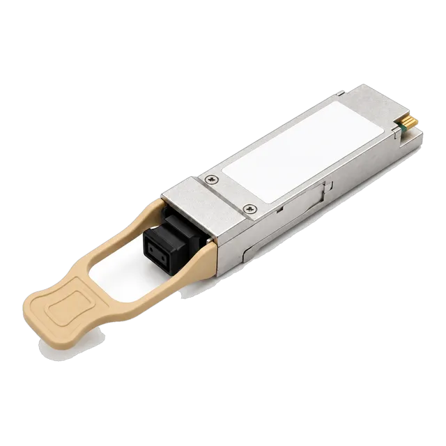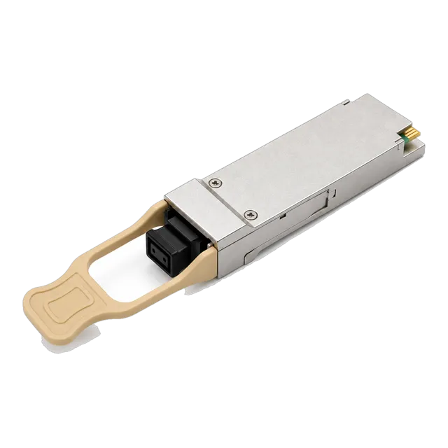
The QSFP 40G SR4 transceiver delivers high-density, low-power short-reach connectivity across four 850 nm multimode lanes using MPO-12 connectors, supporting native 40 Gbps fabric links and 4x10G breakout deployments within a strict 1.9 dB channel insertion loss budget.
01What is a qsfp 40g sr4 optical transceiver?
A qsfp 40g sr4 optical transceiver is a hot-pluggable, four-channel parallel optical module engineered for 40 Gigabit Ethernet short-reach data communications over multimode fibre (MMF). Standardised under IEEE 802.3ba Clause 86 as 40GBASE-SR4 and governed mechanically by the SFF-8436 specification, the module consolidates four independent transmit and four independent receive lanes operating at 10.3125 Gbps per channel. This 4x10G optical architecture enables an aggregate full-duplex throughput of 41.25 Gbps across parallel optical fibres terminated with a male or female multi-fiber push-on (MPO) connector.
Inside the transceiver, an array of four 850 nm Vertical-Cavity Surface-Emitting Lasers (VCSEL) converts electrical transmit signals into optical pulses. On the receiver path, an array of four PIN photodiodes detects incoming light and passes the electrical signals through transimpedance amplifiers (TIA) back to the host switch serializer/deserializer (SerDes). Because each lane operates at the identical line rate of 10GBASE-SR, engineers frequently deploy the 40G QSFP+ SR4 850nm multimode transceiver to bridge 40 Gbps spine or leaf ports directly to legacy 10 Gbps Top-of-Rack (ToR) server access ports using optical breakout assemblies.
02Optical specifications: wavelengths, power levels, and receiver sensitivity
Optical parameters for 40GBASE-SR4 modules are strictly defined by IEEE 802.3ba Table 86-6 and Table 86-7 to ensure multi-vendor interoperability across short-reach multimode links. Each of the four optical lanes operates inside a designated spectral window centered at 850 nm, with an allowable wavelength range of 840 nm to 860 nm and a maximum root-mean-square (RMS) spectral width of 0.65 nm. This narrow spectral emission suppresses chromatic dispersion over graded-index multimode glass.
The following optical performance metrics apply per lane for standard commercial and industrial deployments:
| Parameter (per lane) | IEEE 802.3ba Minimum | Typical Production Value | IEEE 802.3ba Maximum | Units |
|---|---|---|---|---|
| Transmitter Centre Wavelength | 840 | 850 | 860 | nm |
| Average Launch Power | -7.6 | -2.5 | +2.4 | dBm |
| Optical Modulation Amplitude (OMA) | -5.6 | -1.5 | +3.0 | dBm |
| Extinction Ratio (ER) | 3.0 | 3.5 | — | dB |
| Receiver Sensitivity (OMA) | — | -11.5 | -9.5 | dBm |
| Receiver Damage Threshold | +3.4 | — | — | dBm |
| Receiver Overload (Average) | — | — | +2.4 | dBm |
Maintaining the transmit power within the -7.6 dBm to +2.4 dBm window prevents saturation of the receiving PIN photodiode array while supplying sufficient photon energy to overcome connector insertion loss and modal dispersion. For comprehensive form-factor specifications, consult our QSFP transceiver engineering guide.
03MPO-12 connector interface and fiber polarity options
The optical interface of a 40GBASE-SR4 module utilizes an industry-standard MPO-12 receptacle that requires an 8-fibre or 12-fibre parallel multimode patch cord. The transceiver uses only eight optical fibres: the outer four lanes on one side transmit light (Tx1 to Tx4), while the outer four lanes on the opposite side receive light (Rx4 to Rx1). The central four fibre positions (positions 5, 6, 7, and 8) remain unassigned and dark inside the ferrule.
Proper link establishment depends entirely on maintaining correct polarity as defined by TIA-568.3-D. Data centre deployments rely on three primary cabling polarity structures:
- Type-B Polarity (Key-Up to Key-Up): The recommended standard for direct QSFP-to-QSFP connections. The ribbon cable flips fibres completely, mapping Position 1 (Tx1) directly to Position 12 (Rx1) on the mating transceiver, ensuring seamless transmitter-to-receiver alignment without external crossover adapters.
- Type-A Polarity (Key-Up to Key-Down): Employs straight-through mapping (Position 1 to Position 1). When connecting transceivers through Type-A cassette trunks, an A-to-B patch cord or flipped cassette must be introduced on one end to reverse the transmit and receive optical paths.
- Type-C Polarity (Pair-Flipped): Swaps adjacent fiber pairs (1-2, 3-4). While common in legacy duplex routing, Type-C is not recommended for native parallel MPO-12 transceiver optics because it breaks 4-channel lane order.
For unpinned transceivers containing female alignment receptacles, patch cables must feature male MPO connectors equipped with guide pins to ensure sub-micron core alignment during physical mating.
04Transmission distances over OM3, OM4, and OM5 multimode fiber
The maximum transmission reach of a 40G QSFP+ SR4 transceiver depends directly on the effective modal bandwidth (EMB) of the installed laser-optimised multimode fibre (LOMMF). Modal dispersion represents the primary limiting physical factor at 10.3125 Gbps per lane, causing optical pulses to spread temporally as light propagates along multiple modes within the 50 µm core.
IEEE 802.3ba specifies exact link distances based on standard multimode glass types evaluated at an 850 nm operating window:
- OM3 Fibre (2000 MHz·km EMB): Supports standard link lengths up to 100 metres with a maximum allowable channel attenuation of 1.9 dB.
- OM4 Fibre (4700 MHz·km EMB): Extends standard transmission distance up to 150 metres under IEEE standards, maintaining a 1.5 dB total loss budget. High-spec transceivers like our 40GBASE-SR4 QSFP+ 850nm 100-150m MPO transceiver guarantee full compliance across this distance.
- OM4 Extended Reach (eSR4): Enhanced VCSEL drive circuitry allows specialized models to achieve 300 metres to 400 metres over premium OM4 cabling when mated with low-loss MPO connectors.
- OM5 Fibre (WideBand MMF): Provides identical transmission reach to OM4 (150 metres) at the 850 nm wavelength. Although OM5 is optimised for multi-wavelength short wavelength division multiplexing (SWDM) between 850 nm and 953 nm, it operates identically to OM4 when driven by single-wavelength 850 nm SR4 arrays.
Exceeding these distance thresholds degrades the eye opening, triggers Bit Error Rate (BER) spikes beyond the pre-FEC threshold of 10-12, and induces unrecoverable frame drops.
05Worked link loss budget calculation for 40GBASE-SR4
Calculating the optical loss budget ensures a 40GBASE-SR4 link maintains sufficient optical power margin prior to cable installation. According to IEEE 802.3ba Clause 86, the power budget is determined by subtracting the receiver sensitivity from the minimum transmitter output power, while accounting for fibre attenuation, connector insertion loss, and power penalties.
Consider an OM4 structured cabling link running 120 metres through two MPO patch panels (four mated MPO connector pairs total):
- Calculate Minimum Optical Power Budget:
Minimum Tx OMA = -5.6 dBm
Maximum Rx Sensitivity (OMA) = -9.5 dBm
Available Optical Budget = (-5.6 dBm) - (-9.5 dBm) = 3.9 dB - Calculate Multimode Fibre Attenuation:
Cable loss coefficient at 850 nm = 3.0 dB/km (0.003 dB/m)
Fibre attenuation = 120 m × 0.003 dB/m = 0.36 dB - Calculate Total Connector Insertion Loss:
Standard low-loss MPO connector pair = 0.35 dB per mated junction
Four mated MPO junctions = 4 × 0.35 dB = 1.40 dB - Allocate IEEE Dispersion & Jitter Penalties:
Allocated power penalty (intersymbol interference and modal noise) = 1.5 dB - Determine Total Link Loss:
Total Channel Insertion Loss = Fibre Attenuation (0.36 dB) + Connector Loss (1.40 dB) = 1.76 dB
Total Link Budget Consumed = Channel Loss (1.76 dB) + Penalties (1.5 dB) = 3.26 dB - Calculate Net Safety Margin:
Margin = Available Budget (3.9 dB) - Total Link Budget Consumed (3.26 dB) = 0.64 dB
Because the net safety margin is positive (0.64 dB) and the total channel insertion loss (1.76 dB) remains below the IEEE maximum allocation for 150 m OM4 (1.5 dB to 1.9 dB depending on implementation), the link will operate error-free. For custom trunk configurations, verify figures using our optical link budget calculation guide.
0640GBASE-SR4 QSFP+ 4x10G breakout architecture
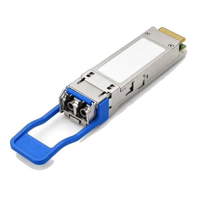
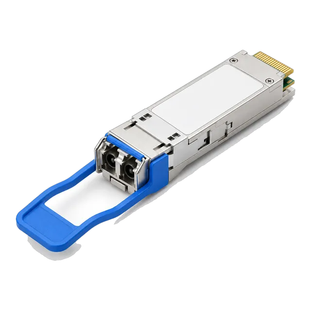
A 40GBASE-SR4 transceiver breaks out into four distinct 10GBASE-SR channels by terminating its 8-fibre parallel optical output into four duplex LC optical connections. Because the physical layer protocol on each lane conforms to standard 10GBASE-R framing (10.3125 Gbps, 64b/66b line code), the optical stream is electrically and optically compatible with standard SFP+ 10G SR optical transceivers.
Implementing this breakout architecture requires specific physical layer cabling and switch port channelisation:
- MPO-to-4x-LC Fanout Assemblies: A female MPO-12 connector branches into four duplex LC uniboot connectors. The Tx fibres from the MPO plug into the Rx ports of the SFP+ modules, while the Rx fibres route to the SFP+ Tx ports.
- Structured Cassette Breakout: MPO trunk cables run from a 40G QSFP+ switch port into a rack-mount optical cassette. The cassette internally fans out the ribbon fibre to four duplex LC front ports, providing structured patching for server racks.
- Port Channelisation Commands: The host network operating system (NOS) must explicitly divide the 40G hardware port into four independent logical 10G interfaces (for example, setting port speed to
4x10Gor executingchannelizedcommands).
Breakout configurations offer massive port density advantages, allowing network designers to collapse 48 server access links into 12 high-density QSFP+ switch interfaces.
07Power consumption, thermal envelope, and SFF-8436 standards
Standard 40G QSFP+ SR4 transceivers consume between 1.0 W and 1.5 W under continuous line-rate traffic, categorising them well within SFF-8436 Power Level 1 (≤1.5 W). This modest power profile is achieved because the 850 nm VCSEL array requires substantially lower drive current than edge-emitting distributed feedback (DFB) lasers or electro-absorption modulated lasers (EML) used in single-mode optics.
Key thermal and electrical parameters mandated by SFF-8436 include:
- Supply Voltage: 3.3 V DC ± 5%, delivered through host rail pins VccTx and VccRx.
- Maximum Inrush Current: Limited to 30 mA per lane to protect host switch hot-swap controllers during module insertion.
- Operating Case Temperature: Standard commercial grade covers 0 °C to +70 °C (32 °F to 158 °F), whereas industrial-temperature (I-Temp) rated transceivers operate reliably from -40 °C to +85 °C.
- Airflow Requirements: High-density switch faceplates with 32 or 48 QSFP+ ports side-by-side generate up to 72 W of optical thermal load per rack unit. Modules require adequate front-to-back or back-to-front forced airflow to prevent internal laser junction temperatures from exceeding +100 °C.
Operating an optical module above its rated case temperature accelerates VCSEL degradation, reducing laser lifespan and triggering thermal drift in transmitter center wavelengths.
08Digital diagnostic monitoring registers in SFF-8636
Digital Diagnostic Monitoring (DDM), also referred to as Digital Optical Monitoring (DOM), provides real-time telemetry across internal operating conditions via the two-wire I2C management interface defined by SFF-8636. Memory address A0h contains static EEPROM information (vendor, serial number, compliance codes), while Upper Page 00h and Upper Page 03h track dynamic physical measurements and programmable alarm flags.
Network management systems poll five essential operational parameters via SFF-8636 registers:
- Internal Transceiver Temperature (Bytes 22-23): Internally measured case temperature reported in 1/256 degrees Celsius increments.
- Internal Supply Voltage (Bytes 26-27): Host rail voltage reported in 0.1 mV increments, maintaining a nominal reading of 33,000 (3.30 V).
- Tx Bias Current per Lane (Bytes 42-49): Real-time laser drive current per channel in 2 µA increments. A gradual increase in bias current indicates aging VCSEL arrays compensating for diminished optical output.
- Tx Optical Output Power per Lane (Bytes 50-57): Launch power measured in 0.1 µW increments, providing immediate verification of transmitter health.
- Rx Received Optical Power per Lane (Bytes 58-65): Average optical input power per channel in 0.1 µW increments, indicating dirty end-faces, macrobends, or broken fibres.
High/low alarm and warning threshold registers alert network administrators to anomalies before link degradation triggers frame loss. Learn more about interpreting telemetry in our guide to understanding DDM diagnostics.
09qsfp 40g sr4 vs 40GBASE-BiDi, LR4, and AOC options
Selecting between 40G optical interfaces depends on cable plant reach, existing fiber infrastructure, and transceiver capital expense. While a 40gbase sr4 qsfp transceiver requires an 8-fibre parallel multimode path, alternatives like 40GBASE-BiDi utilise standard duplex LC multimode fiber, and 40GBASE-LR4 optics operate over single-mode fiber infrastructure.
The following engineering comparison highlights key operational trade-offs:
| Transceiver Type | Media Type | Optical Connector | Standard Reach | Nominal Power | Relative Cost Factor |
|---|---|---|---|---|---|
| 40GBASE-SR4 | Multimode (OM3 and OM4) | MPO-12 | 100 m / 150 m | 1.2 W | 1.0x (Baseline) |
| 40GBASE-BiDi | Multimode (OM3 and OM4) | Duplex LC | 100 m / 150 m | 3.5 W | 2.2x |
| 40GBASE-LR4 | Single-Mode (G.652) | Duplex LC | 10 km | 3.5 W | 3.8x |
| 40G Active Optical Cable (AOC) | Integrated MMF Ribbon | Non-removable | 1 m to 30 m | 1.2 W | 0.8x |
| 40G Direct Attach Copper (DAC) | Twinaxial Copper | Copper Assembly | 1 m to 5 m | 0.1 W | 0.3x |
Where intra-rack links require less than 5 metres, engineers deploy passive copper using our DAC cable engineering guide. For medium-distance single-mode links between campus buildings or data hall aggregation points, switch to the 40G QSFP+ LR4 1310nm 10km transceiver to avoid parallel multimode distance barriers.
10Host switch port configuration and breakout commands
Configuring a QSFP+ switch port for 40GBASE-SR4 operation requires defining the physical operating mode, channelization state, and forward error correction settings inside the host operating system. Standard 40GBASE-R does not mandate Clause 74 Firecode FEC (Forward Error Correction), meaning 40G links operate with low latency (sub-100 nanoseconds physical layer processing) compared to 25G and 100G architectures.
When deploying native 40 Gbps links, the configuration workflow follows standard line settings:
- Verify transceiver insertion using host diagnostic tools:
show interface transceiver detailorshow inventory. - Ensure the interface speed is explicitly set to 40 Gbps:
speed 40000orspeed 40g. - Confirm autonegotiation is disabled if required by the hardware architecture:
no negotiation auto.
When configuring a 4x10G breakout link, execute the hardware sub-interface command on the physical QSFP+ port:
- Access the hardware interface configuration:
interface breakout port 1/1 map 10g-4xorinterface ethernet 1/1/1 speed 10g-4x. - Verify that the switch creates four independent child interfaces (for example,
Ethernet 1/1/1throughEthernet 1/1/4). - Assign matching VLAN, MTU (typically 9000 or 9216 for Jumbo Frames), and link parameters to each 10G sub-interface to align with the downstream SFP+ ports.
Failure to commit channelization commands leaves the QSFP+ port attempting to negotiate a single 40G logical interface, preventing link up across split LC endpoints.
11Common failure modes and physical layer troubleshooting
Physical layer failures on 40GBASE-SR4 links most frequently stem from end-face contamination on the 12-fiber MPO ferrule, incorrect cable polarity, or guide-pin mismatches. Because an MPO ferrule presents 12 optical surfaces across a single mechanical interface, a single microscopic dust particle on lane 1 or lane 12 will take down an entire 40G channel or break a specific 10G breakout path.
Field engineers isolate link faults through a systematic physical diagnosis:
- End-Face Contamination: Inspect the MPO ferrule with an automated fiber microscope. Clean both mating surfaces using a mechanical IBC MPO push cleaner or wet-to-dry cleaning cassette. Never mate dry connectors if solvent residues or dust oils are visible.
- Pin Mismatch (Male vs Female): Transceiver receptacles are unpinned (female, with alignment holes). Connecting an unpinned patch cord to an unpinned transceiver results in optical core misalignment and attenuation exceeding 10 dB. Connecting a pinned patch cord to a pinned transceiver can crack internal alignment pins.
- Polarity Inversion: If DDM shows active Tx power on switch A but zero Rx power on switch B, verify ribbon polarity. An inverted Type-A cable will direct transmit signals into transmit lasers instead of photodiode receivers.
- High Insertion Loss: Use an optical power meter (OPM) calibrated to 850 nm to measure individual lane power. If received optical power drops below -11 dBm, inspect for macrobending along trunk trays or damaged internal fibers.
Adhering strictly to IEC 61300-3-35 inspection standards eliminates over 80% of intermittent transceiver link-loss issues.
12Environmental compliance, eye safety, and reliability metrics
Industrial and commercial optical transceivers must satisfy rigorous international safety and environmental regulations before deployment in enterprise environments. Transmitters operating at 850 nm fall under Class 1 laser safety standards as defined by IEC 60825-1:2014 and US FDA 21 CFR 1040.10, ensuring that optical emissions remain completely eye-safe under normal operation and single-fault failure conditions.
Hardware reliability and material standards dictate long-term lifecycle performance:
- Telcordia GR-468-CORE: Defines environmental stress screening for optoelectronic devices, including mechanical shock (1500 G, 0.5 ms), cyclic moisture resistance, high-temperature storage testing (+85 °C for 2000 hours), and vibration resistance (20 G, 10 Hz to 2000 Hz).
- Mean Time Between Failures (MTBF): Quality 40G QSFP+ SR4 transceivers achieve calculated MTBF values exceeding 1,000,000 hours at a continuous operating temperature of +40 °C, using Bellcore or Telcordia SR-332 reliability prediction models.
- RoHS & REACH Compliance: Products must conform to EU Directive 2011/65/EU (RoHS 2/3), restricting hazardous substances including lead, mercury, cadmium, and hexavalent chromium in transceiver solder and optical component housing.
- Electrostatic Discharge (ESD): Human Body Model (HBM) Class 1C and Charged Device Model (CDM) Class C3 per JEDEC standards ensure pins withstand up to 1000 V ESD events during hot-plug insertion.
Specifying fully compliant components guarantees continuous uptime in high-density data centres and carrier switching centers.
13RFQ engineering checklist for 40G QSFP+ SR4 procurement
Procuring 40GBASE-SR4 transceivers requires providing precise optical, mechanical, and EEPROM programming specifications to vendor engineering teams to prevent compatibility issues on deployment. Incorporate the following technical requirements directly into your engineering bill of materials (BOM) or tender documents:
- Optical Interface & Protocol: IEEE 802.3ba 40GBASE-SR4 compliant, 41.25 Gbps aggregate throughput, 4x 850 nm VCSEL array, PIN receiver.
- Form Factor & Pinout: SFF-8436 QSFP+ Multi-Source Agreement (MSA) compliant, hot-pluggable 38-pin electrical interface.
- Optical Connector & Pinning: MPO-12 optical receptacle, unpinned (female), compatible with male pinned patch cords.
- Reach & Fiber Support: Guaranteed minimum 100 m on OM3 (2000 MHz·km) and 150 m on OM4 (4700 MHz·km) multimode fiber.
- Power Budget & Sensitivity: Minimum optical power budget of 3.9 dB; Tx OMA minimum -5.6 dBm, Rx sensitivity (OMA) ≤ -9.5 dBm per lane.
- Power Dissipation: SFF-8436 Power Level 1, maximum power consumption ≤ 1.5 W per module under full line-rate traffic.
- DDM / DOM Implementation: SFF-8636 compliant digital diagnostics reporting real-time per-lane Tx Power, Rx Power, Bias Current, Vcc, and Case Temperature.
- Target Host Platform EEPROM Coding: Custom binary coding for the specific host switch vendor, hardware model, and firmware release to bypass third-party optic warning flags.
- Temperature Rating: Commercial (0 °C to +70 °C) or Industrial (-40 °C to +85 °C) depending on installation environment.
Explore our full catalogue of optical modules on the 40G QSFP+ product category page or contact our technical sales team for platform coding verification prior to order placement.
14Frequently asked questions
What connector does a QSFP 40G SR4 transceiver use?
A QSFP 40G SR4 transceiver uses an MPO-12 (Multi-Fiber Push-On) connector interface. It operates with an unpinned (female) optical receptacle that receives a male MPO-12 patch cable equipped with alignment pins, utilizing 8 of the 12 fiber positions for transmission.
Can I break out a 40GBASE-SR4 port to four 10G SFP+ ports?
Yes, a 40GBASE-SR4 port breaks out into four 10GBASE-SR connections using an MPO-to-4x-LC duplex fanout cable. The host switch port must be channelised into 4x10G mode, because each optical lane operates at the identical 10.3125 Gbps line rate as standard 10G SR optics.
What is the maximum distance for a 40G QSFP+ SR4 module?
Under IEEE 802.3ba standards, a 40G QSFP+ SR4 module transmits up to 100 metres over OM3 multimode fibre and up to 150 metres over OM4 multimode fibre. Extended-reach variants (eSR4) can achieve up to 300 to 400 metres over high-bandwidth OM4 cabling.
What is the difference between 40GBASE-SR4 and 40GBASE-BiDi?
40GBASE-SR4 uses an MPO-12 connector across eight multimode fibres (four transmit, four receive) at 850 nm. In contrast, 40GBASE-BiDi uses a standard duplex LC multimode cable, transmitting two bidirectional 20 Gbps channels over two wavelengths (850 nm and 900 nm).
Does 40G QSFP+ SR4 support single-mode fibre?
No, 40G QSFP+ SR4 optics use 850 nm VCSEL lasers designed strictly for 50/125 µm multimode fibre. Connecting an SR4 transceiver to 9/125 µm single-mode fibre induces severe modal mismatch and excessive attenuation, resulting in complete optical link failure.
Why are four fibres unused in an MPO-12 cable for 40G SR4?
The QSFP+ MSA architecture allocates four lanes for transmit and four lanes for receive. An MPO-12 connector ferrule arranges 12 fibres horizontally; 40GBASE-SR4 uses the outer four positions on each side (1-4 and 9-12), leaving the middle four positions (5-8) unassigned.
Technical review note: confirm model-specific specifications with the product datasheet and the intended host documentation. Product images and application photographs are illustrative.
Discuss this with our team