Specifying an outdoor light switch requires balancing ingress protection against internal thermal dissipation, selecting minimum IP66 UV-stabilised enclosures, robust 6 kV surge suppression, and IEEE 802.3at/bt compliance for low-voltage exterior smart lighting deployments.
01Engineering requirements for an outdoor light switch
An outdoor light switch isolates electrical contacts or digital control circuits from ambient humidity, sub-zero temperatures, solar radiation, and particulate contamination. In industrial perimeter lighting, municipal pathways, and commercial facilities, deploying an exterior lighting control requires evaluating both physical switching mechanisms and connected low-voltage network devices. Whether operating as a 230 V alternating current (AC) electromechanical relay or an Internet Protocol (IP) based Power over Ethernet (PoE) controller, the unit must maintain operational integrity under severe environmental stresses.
Standard indoor switches fail rapidly outdoors due to capillary water ingress, diurnal condensation cycles, and ultraviolet (UV) degradation of thermoplastic faceplates. When specifying hardware, engineers must delineate between standard line-voltage physical switches and digital power distribution equipment such as an outdoor PoE switch that activates low-voltage smart luminaires over structured copper cabling. Both form factors require continuous sealing, chemical resistance against atmospheric hydrocarbons, and high mechanical impact endurance compliant with international standards.
02Ingress protection: decoding IP65, IP66, and IP67 enclosures
Ingress Protection (IP) ratings defined under IEC 60529 quantify the barrier performance of an electrical enclosure against solid foreign objects and liquid intrusion. For any outdoor waterproof light switch, the minimum acceptable rating for covered exterior locations is IP65, whilst fully exposed building perimeters demand IP66 or IP67 ratings to withstand wind-driven precipitation and high-pressure hose washdowns.
- IP65: Dust-tight enclosure offering complete protection against contact, tested against water jets projected by a 6.3 mm nozzle at 12.5 litres per minute at 30 kPa for 3 minutes from a distance of 3 metres.
- IP66: Dust-tight enclosure designed for heavy seas or powerful water jets projected by a 12.5 mm nozzle at 100 litres per minute at 100 kPa pressure, preventing harmful liquid penetration.
- IP67: Dust-tight construction permitting temporary immersion in water up to 1 metre depth for 30 minutes without ingress exceeding specified safety limits.
Where industrial plants or marine infrastructure require continuous washdowns, a weatherproof switch certified to IP66 ensures that water projected at high velocity cannot displace elastomeric seals or penetrate the internal switch cavity.
03Weatherproof switch enclosures: polycarbonate versus die-cast aluminium
Enclosure material selection directly dictates the structural longevity and impact resistance of an exterior switch in harsh industrial environments. Polycarbonate thermoplastic and die-cast aluminium alloys represent the two primary engineering choices, each addressing specific environmental degradation mechanisms.
UV-stabilised polycarbonate provides high electrical insulation, eliminating stray voltage risks on the outer chassis without requiring earth bonding jumpers to the housing. It achieves high impact resistance, typically rated at IK08 or IK09 under EN 62262, while offering natural immunity to coastal salt spray and acidic industrial atmospheres. However, polycarbonate exhibits poor thermal conductivity (approximately 0.2 W/m·K), which traps heat generated by internal transformers or solid-state relay drivers.
Die-cast aluminium (typically LM6 or ADC12 alloy with powder-coated or anodised passivisation) provides superior mechanical strength rated at IK10, exceptional thermal dissipation (thermal conductivity around 120 to 160 W/m·K), and comprehensive electromagnetic shielding. Aluminium is the preferred material for an outdoor electrical switch installation operating in extreme ambient temperatures or locations prone to physical vandalism, provided appropriate galvanic isolation prevents contact with dissimilar metals.
04Outdoor waterproof light switch wiring and gland termination
Cable gland termination preserves the stated IP rating of an outdoor switch waterproof junction by establishing a continuous compression barrier around incoming conductors. Using inappropriate knockouts or unsealed metric threads introduces capillary paths through which moisture enters the enclosure during nocturnal cooling cycles.
- Select matching gland specifications: Deploy nickel-plated brass or nylon glands featuring ethylene propylene diene monomer (EPDM) or silicone compression rings matched precisely to the outside cable diameter (OD).
- Implement blind threaded entries: Ensure enclosure entries feature cast internal threads or use locking nuts fitted with rubber O-rings seated against flat exterior sealing faces.
- Form functional drip loops: Dress incoming power or Category 6 data cables downward below the entry port before curving upward into the gland, forcing accumulated precipitation to drop harmlessly away from the entry interface.
- Apply internal vapor barriers: Seal conduit entry points using non-hardening duct-sealing putty to prevent internal moisture migration from warm building interiors into colder exterior junction boxes.
Failure to implement drip loops allows water tracking along the cable sheath to exert static hydrostatic pressure against the gland gasket, compromising the interior of a weatherproof outdoor light switch over prolonged service.
05Exterior light switch power delivery: mains AC versus low-voltage PoE
Modern exterior illumination systems split between traditional mains 230 V AC switching and low-voltage direct current (DC) distribution governed by IEEE 802.3 standards. While a conventional exterior light switch physically breaks the phase conductor supplying 230 V AC to outdoor fixtures, digital lighting infrastructures increasingly leverage Ethernet cabling to deliver combined control data and power.
Mains-voltage switching demands heavy steel-wire armoured (SWA) cables, dedicated earthing rods, external RCD (residual current device) breakers, and certified junction enclosures. Conversely, low-voltage illumination operating over Power over Ethernet uses IEEE 802.3af (15.4 W), IEEE 802.3at (30 W), or IEEE 802.3bt (up to 90 W) profiles to drive solid-state LED luminaires directly from network hardware.
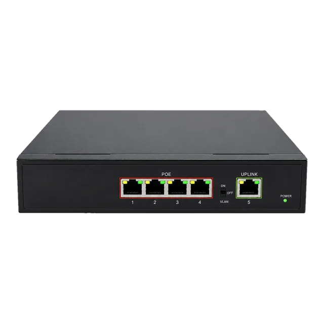
Deploying a hardened Gigabit PoE IP Ethernet switch allows building automation controllers to manage, dim, schedule, and meter outdoor lighting circuits centrally over Cat6a cabling. This eliminates local high-voltage relays, cuts installation labour, and integrates exterior lights seamlessly into building management networks.
06Selecting an outdoor switch for smart lighting automation
An outdoor smart light switch requires dedicated protocol handling, robust memory retention across utility outages, and deterministic actuation under network latency constraints. Exterior automation utilizes solid-state relay (SSR) modules or networked PoE endpoints governed by open protocols including BACnet/IP, Modbus TCP, or MQTT.
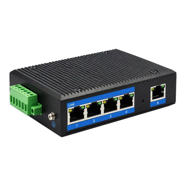
When engineers implement networked lighting arrays on site perimeters or remote substations, an industrial-grade switch provides the required network backbone. A unit such as the Outdoor Industrial Gigabit Ethernet Switch operates reliably from 10 V to 47 V DC input power across a -40°C to +85°C operating window. It aggregates local IP lighting controllers, optical surveillance sensors, and exterior manual override switches across remote field poles.
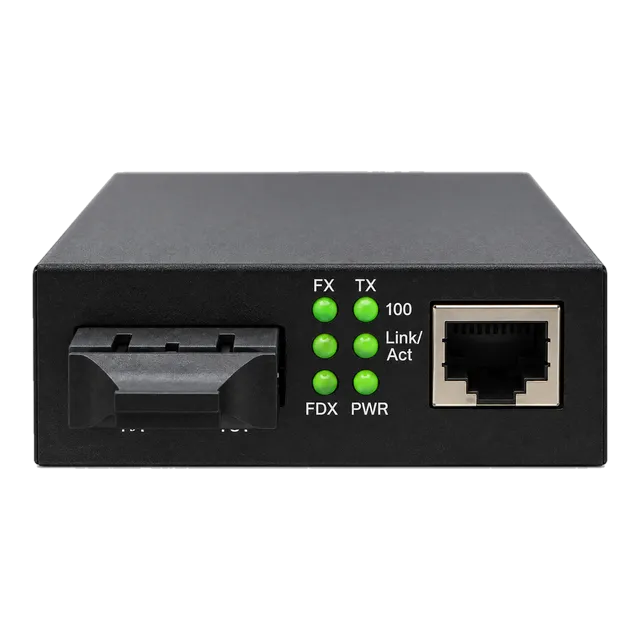
For architectural lighting transitions across extended distances, coupling local PoE drivers with single-mode optical runs via a media converter guarantees low-latency communication immune to ground potential differences. System architects can evaluate structured power distribution using our comprehensive PoE switch standards power budget guide to balance total dynamic loads across external port arrays.
07Thermal management and operating temperature ranges
Operating temperatures inside an unventilated, sealed weather resistant switch enclosure often rise 20°C to 30°C above ambient conditions due to direct solar radiation absorption. When designing an outdoor lighting control station, thermal equilibrium calculations must incorporate ambient atmospheric heat, internal module dissipation, and solar irradiance.
Industrial environments experience ambient shifts between -40°C in winter continental climates and +45°C under desert conditions. Solar loading adds up to 1,120 W/m² of radiative energy against exposed enclosure lids. Standard commercial silicon and low-grade terminal blocks fail in these environments through dielectric embrittlement, contact expansion, or optical controller thermal shutdown.
Specifying a true weather resistant light switch or industrial power module requires internal solid-state components rated for continuous operation from -40°C to +75°C. In high-insolation zones, engineers must fit passive sun shields (solar radiation covers) with a minimum 15 mm air gap over the enclosure to promote natural convective airflow across the external housing faces.
08Surge suppression and grounding standards for exterior switch installations
Surge protection for an outdoor power switch or external data line must conform to IEC 61000-4-5 testing standards to mitigate transient overvoltages from indirect lightning discharges and heavy inductive load switching. Exterior installations run elevated risks of high-voltage transients coupled capacitively into power and communication cables.
To safeguard internal circuitry, an outdoor rated switch requires multi-stage transient voltage surge suppression (TVSS). For mains AC switching circuits, this demands Type 1 or Type 2 surge protective devices (SPDs) incorporating metal oxide varistors (MOVs) and gas discharge tubes (GDTs) capable of diverting 10 kA to 20 kA (8/20 µs waveform) safely to earth. Network-connected PoE lighting switches should incorporate minimum 6 kV differential and common-mode surge protection on all RJ45 copper ports.
Equipotential bonding must link the enclosure ground lug directly to the facility earth network using a copper conductor of at least 6 mm² (AWG 10) cross-sectional area, ensuring path impedance remains below 1 ohm to prevent ground potential rises from destroying exterior control interfaces.
09Outdoor rated switch specification comparison
Selecting an outdoor rated light switch requires comparing environmental ratings, internal contact configurations, and physical limitations against installation environments. The table below outlines parameters across four prevalent industrial and commercial exterior switching categories.
| Switch Architecture | Ingress & Impact Rating | Operating Temp Range (°C) | Nominal Switching Capacity | Recommended Application Field |
|---|---|---|---|---|
| Mains Mechanical Rocker | IP66 / IK08 | -20 to +60 | 250 V AC / 16 A Resistive | Isolated exterior manual perimeter lights, plant walkways |
| Smart Solid-State Relay | IP65 / IK07 | -25 to +70 | 100–240 V AC / 10 A | Dimmable architectural lighting, automated building facades |
| Industrial PoE Network Switch | IP40 inside IP66 box / IK10 | -40 to +85 | PoE+ (30 W per port), 48 V DC | Smart IP-enabled lighting fixtures, pole-mounted CCTV arrays |
| Rotary Exterior Isolator | IP67 / IK09 | -35 to +75 | 415 V AC / 32 A Inductive | High-output sports floodlighting, industrial distribution hubs |
For installations requiring long-range fiber backhaul to an exterior lighting junction, integrating a hardened industrial switch inside an external enclosure allows network engineers to combine multi-gigabit data uplinks with local power control over wide facilities.
10Calculating thermal rise and power dissipation in sealed enclosures
Calculating steady-state internal temperature prevents component overheating in fully sealed, non-ventilated IP66 or IP67 enclosures housing an outdoor switch. Enclosure heat dissipation relies entirely on external surface conduction, natural convection, and radiation.
To determine internal temperature rise, use the standard steady-state heat transfer formula:
ΔT = P / (k × A)
Where:
- ΔT = Temperature rise inside the enclosure above external ambient (°C)
- P = Total internal power dissipated as heat (Watts)
- k = Effective overall heat transfer coefficient (typically 5.5 W/m²·K for painted sheet steel, 10 to 12 W/m²·K for cast aluminium, and 3.5 W/m²·K for polycarbonate)
- A = Total effective exposed surface area of the enclosure (m²), excluding the wall-mounted rear surface
Worked Engineering Example:
Consider an IP66 polycarbonate exterior enclosure measuring 0.3 m (H) × 0.2 m (W) × 0.15 m (D), containing an industrial smart relay and power converter dissipating a combined 18 W. The enclosure is mounted flush to a wall, leaving top, bottom, front, and two side faces exposed.
- Front face: 0.3 × 0.2 = 0.06 m²
- Top and bottom faces: 2 × (0.2 × 0.15) = 0.06 m²
- Side faces: 2 × (0.3 × 0.15) = 0.09 m²
- Total exposed surface area (A): 0.06 + 0.06 + 0.09 = 0.21 m²
- Polycarbonate transfer coefficient (k): 3.5 W/m²·K
ΔT = 18 W / (3.5 W/m²·K × 0.21 m²) = 18 / 0.735 ≈ 24.5°C
If the maximum ambient temperature under direct sunlight reaches 40°C, the internal enclosure temperature will reach 40°C + 24.5°C = 64.5°C. This calculation proves that standard commercial components rated only to 50°C or 60°C will fail. The installation strictly requires industrial-grade components rated for operation up to 75°C or 85°C.
11Procurement checklist for exterior switch deployment
A structured technical evaluation matrix guarantees that every weather proof switch and control station delivered to an engineering site aligns with physical, electrical, and regulatory specifications.
- Ingress and Impact Rating: Verify test certification confirming minimum IP66 under IEC 60529 and minimum IK08 under EN 62262.
- UV Material Stabilization: Confirm enclosure polycarbonate matches UL 746C (f1 grade) for exterior weathering exposure without loss of mechanical tensile strength.
- Gasket Formulation: Specify continuous one-piece silicone or vulcanised neoprene gaskets resistant to ozone, microbial attack, and thermal plastic deformation.
- Fastener Composition: Require Grade 316 (A4) stainless steel external captive screws and mounting brackets to prevent galvanic pitting in coastal atmospheres.
- Electrical Clearances: Verify compliance with IEC 60947-1 creepage and clearance distances across operating voltages up to 500 V insulation rating.
- Thermal Verification: Validate that total internal component thermal ratings exceed calculated maximum internal box temperature by at least 15°C margin.
- Surge and EMC Ratings: Mandate minimum 6 kV common mode surge capability adhering to IEC 61000-4-5 standards on all energized and signaling paths.
12Commissioning and testing your outdoor electrical switch installation
Commissioning an outdoor switch requires systematic verification of mechanical seal integrity, insulation resistance, earth loop impedance, and thermal profiles under continuous rated load. The following procedure guarantees field reliability before handover.
- Perform insulation resistance testing: Apply a calibrated 500 V DC test between live conductors and the protective earth circuit; verify resistance exceeds 50 MΩ to ensure no moisture bridging has occurred during cable pulling.
- Verify torque settings: Use an insulated torque screwdriver to tighten terminal connections and cable gland compression nuts to manufacturer-specified Newton-metre (N·m) ratings, preventing conductor creeping or gasket pinching.
- Inspect gasket seating: Visually inspect the elastomeric perimeter seal prior to closing cover screws; verify zero pinching, warping, or particle entrapment along the sealing track.
- Conduct thermal imaging analysis: Energise connected luminaire circuits at full design load for 120 minutes; scan internal terminal blocks and switching relays with a calibrated infrared thermographic camera to verify no anomalous resistive hot spots exist.
- Validate autonomous actuation: Cycle manual overrides, photocell sensors, or software-driven PoE power management scripts across three complete switching sequences to confirm deterministic operation.
Documenting initial thermographic and insulation metrics establishes baseline performance data, streamlining predictive maintenance cycles across the operational lifespan of the exterior lighting infrastructure.
13Frequently asked questions
What IP rating is required for an outdoor light switch?
An outdoor light switch requires a minimum of IP65 for covered or semi-sheltered locations, protecting against dust and low-pressure water sprays. For unsheltered exterior walls subject to wind-driven rain or industrial washdowns, specify IP66 to ensure complete protection against powerful water jets from any direction.
Can standard indoor light switches be installed inside outdoor weatherproof boxes?
Standard indoor switches can be mounted inside outdoor enclosures only if the outer box provides certified IP66 sealing with an integrated exterior membrane actuator. However, indoor switch terminals lack corrosion resistance, making purpose-built, sealed outdoor switches significantly more reliable against diurnal condensation.
Why do outdoor light switches experience internal condensation?
Internal condensation occurs when ambient temperatures drop rapidly at night, causing the air inside a sealed, warm enclosure to cool past its dew point. To prevent water pooling on live terminals, use breathable ePTFE membrane vent plugs that balance interior pressure while blocking liquid water ingress.
How does Power over Ethernet compare to mains outdoor lighting switches?
Power over Ethernet delivers low-voltage 48 V DC power and digital data over structured Cat6a cabling, eliminating high-voltage AC conduits, local junction boxes, and licensed mains wiring. PoE switching enables centralised scheduling, individual fixture dimming, and integrated backup power via uninterrupted power supply systems.
What is the difference between IP66 and IP67 outdoor switches?
An IP66 switch resists high-pressure, powerful water jets (100 kPa at 100 litres per minute) directed from any angle, making it ideal for rain, sea spray, and washdowns. An IP67 switch withstands temporary continuous water submersion up to 1 metre depth for 30 minutes.
Do exterior light switches require dedicated surge protection?
Yes, exterior light switches require dedicated surge protection compliant with IEC 61000-4-5. Outdoor wiring easily couples transient voltages from nearby lightning strikes and inductive load switching. Installers should fit minimum 6 kV to 10 kV surge protective devices upstream or directly inside the switch assembly.
Technical review note: confirm model-specific specifications with the product datasheet and the intended host documentation. Product images and application photographs are illustrative.
Discuss this with our team