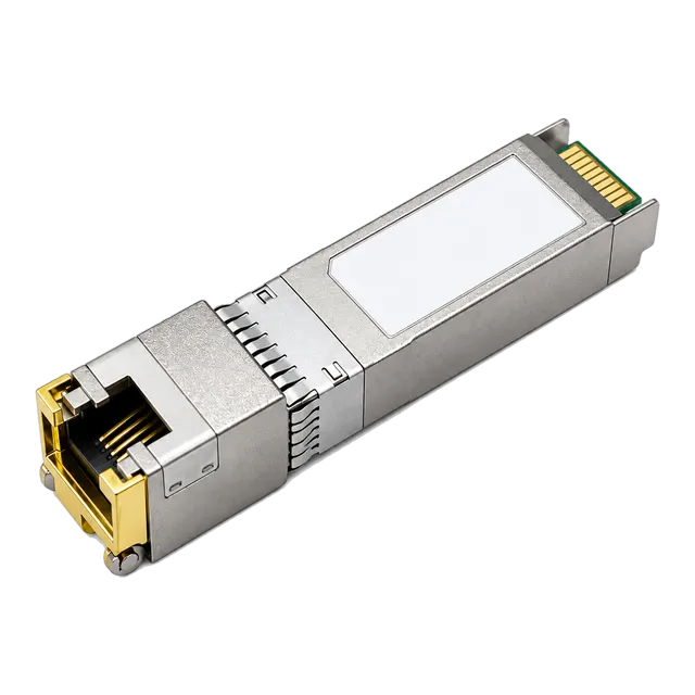
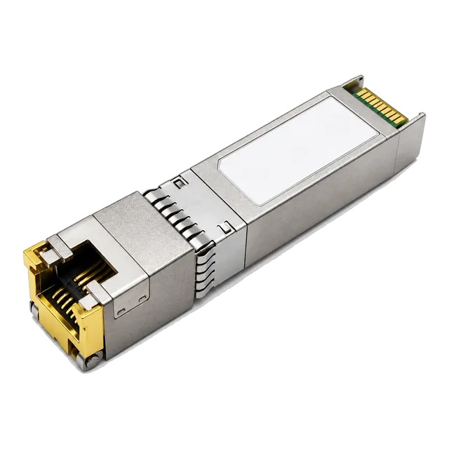
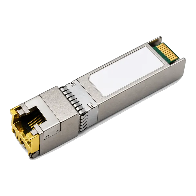
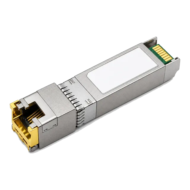
An SFP 10G SR transceiver delivers 10 Gbps over OM3 up to 300 m and OM4 to 400 m at under 1.0 W, making it the premier choice for short-reach multimode links alongside 10GBASE-T copper alternatives.
01What is an SFP 10G SR optical transceiver?
An sfp 10g sr is an enhanced small form-factor pluggable optical module engineered for 10 Gigabit Ethernet connectivity across short-reach multimode optical fibre. Operating under the IEEE 802.3ae 10GBASE-SR specification, this 10g sfp module transmits at a nominal wavelength of 850 nm using an internal Vertical-Cavity Surface-Emitting Laser (VCSEL) and a PIN photodetector receiver. Designed to mate with duplex LC connectors, the optical interface standardises high-throughput aggregation within enterprise data centres, carrier access rooms, and campus server racks.
Standardised under the SFF-8431 electrical interface and SFF-8472 management interface specifications, the 10 gigabit sfp supports Digital Diagnostic Monitoring (DDM). This diagnostic architecture grants real-time visibility into internal module temperature, supply voltage, laser bias current, transmitted optical power, and received optical power. For systems engineers evaluating physical layer architectures, review our analysis in Small Form Factor Pluggable Module: Engineering & RFQ Guide to contextualise mechanical constraints across legacy and high-density installations.
02How does 10GBASE-SR compare with other 10G optical standards?
The IEEE 802.3ae standard establishes distinct optical physical layer specifications to cover distances from short multimode patching to extended single-mode metro spans. While the 10g base sr standard relies on an 850 nm source restricted to multimode infrastructure, alternative interfaces such as 10GBASE-LR and 10GBASE-ER use 1310 nm and 1550 nm single-mode lasers for significantly greater transmission ranges.
| Optical Standard | Fibre Medium | Wavelength (nm) | Target Reach (m) | Typical Power (W) |
|---|---|---|---|---|
| 10GBASE-SR | Multimode (OM3 and OM4) | 850 | 300 / 400 | < 1.0 |
| 10GBASE-LR | Single-Mode (OS2) | 1310 | 10,000 | < 1.2 |
| 10GBASE-ER | Single-Mode (OS2) | 1550 | 40,000 | < 1.5 |
| 10GBASE-ZR | Single-Mode (OS2) | 1550 | 80,000 | < 2.0 |
Selecting between an sfp 10gbase sr optic and an LR module depends entirely on existing structured cabling. While single-mode optics mitigate modal dispersion over vast campuses, multimode 850 nm systems maintain significant cost advantages within intra-hall and top-of-rack deployments. For broader wavelength allocation principles, read our Fiber Optic Wavelengths: Network Transmission Windows Guide.
03What are the maximum transmission distances on OM1, OM2, OM3, and OM4 fibre?
Transmission reach for an sfp 10g sr transceiver is determined strictly by the modal bandwidth of the installed multimode fibre, as modal dispersion limits signal integrity over legacy cores. Under ISO/IEC 11801 and TIA-568 standards, multimode grades exhibit vastly divergent effective modal bandwidth ratings at the 850 nm window.
- OM1 (62.5/125 µm, 200 MHz·km): 33 metres maximum reach.
- OM2 (50/125 µm, 500 MHz·km): 82 metres maximum reach.
- OM3 (50/125 µm laser-optimised, 2000 MHz·km): 300 metres maximum reach.
- OM4 (50/125 µm laser-optimised, 4700 MHz·km): 400 metres maximum reach.
- OM5 (50/125 µm wideband, 4700 MHz·km): 400 metres maximum reach.
Deploying a 10 gig sfp across legacy OM1 or OM2 cabling introduces rapid inter-symbol interference (ISI) beyond short runs. Upgrading horizontal links to OM3 or OM4 allows full utilisation of the 10 Gigabit Ethernet channel up to modern facility limits.
04How do you calculate the optical link budget for an SFP 10G SR link?
Calculating the optical link budget requires deducting total channel insertion losses from the difference between minimum optical launch power and maximum receiver sensitivity. IEEE 802.3ae Clause 52 defines the baseline physical medium dependent (PMD) parameters for 10GBASE-SR channels.
Consider an OM3 link spanning 250 metres with two intermediate LC patch panels:
- Minimum Transmit Power ($P_{\text{tx\_min}}$): -7.3 dBm
- Receiver Sensitivity ($P_{\text{rx\_sens}}$): -9.9 dBm
- Available Power Budget: $-7.3 - (-9.9) = 2.6\text{ dB}$
- Fibre Attenuation: $3.0\text{ dB/km} \times 0.25\text{ km} = 0.75\text{ dB}$
- Connector Loss: 4 mating pairs (2 patch cords) $\times 0.35\text{ dB} = 1.40\text{ dB}$
- Total Channel Insertion Loss: $0.75 + 1.40 = 2.15\text{ dB}$
- Operating Margin: $2.60 - 2.15 = 0.45\text{ dB}$
Because this calculated margin of 0.45 dB is thin, pristine connector end-faces are essential. Cleanliness prevents link flapping caused by contaminated patch points. For deeper analysis into channel verification, consult our guide on Optical link budget: why a 20 km module may not reach 20 km.
05When should you deploy 10GBASE-T copper RJ45 instead of SFP 10G SR optics?
A 10GBASE-T copper RJ45 transceiver is preferred over an sfp 10g sr module when integrating existing twisted-pair Cat6a horizontal plant without incurring the capital expense of optical re-cabling. Standardised under IEEE 802.3an, 10GBASE-T enables direct connection to legacy patch panels, copper server network interface cards (NICs), and structured RJ45 distribution frames.
Where short patch runs allow, modules like the 10G SFP+ to RJ45 Copper 10GBASE-T 30m Cat6a/Cat7 for Enterprise Switch / Server provide robust aggregation for dense rack enclosures. For sprawling enterprise layouts, extended-reach units such as the 10G SFP+ Copper RJ45 10GBASE-T 30-100m - t7 Transceiver with DDM deliver backward compatibility across 100-metre Cat6a runs. For architectural tradeoffs between these media, read our operational review on Copper or fiber at the access layer: 10GBASE-T SFP+ in practice.
06How do 10G SFP SR optics compare to DAC and AOC cables?
Direct Attach Copper (DAC) cables, Active Optical Cables (AOC), and 10g ethernet sfp SR modules occupy distinct operational tiers based on distance, latency, power budgets, and physical flexibility. System designers must match the interconnect medium to physical rack distance constraints.
| Interconnect Type | Max Reach (m) | Latency (ns) | Power per End (W) | Cost Profile |
|---|---|---|---|---|
| Passive DAC | 5 to 7 | < 10 | < 0.1 | Lowest |
| Active Optical Cable (AOC) | 30 | ~250 | ~0.6 | Moderate |
| 10GBASE-SR (Optical Transceiver) | 300 (OM3) / 400 (OM4) | ~250 | ~0.8 to 1.0 | Flexible / Moderate |
| 10GBASE-T (Copper Transceiver) | 30 to 100 | ~1500 to 2500 | 2.0 to 2.5 | Medium |
While passive copper cables dominate top-of-rack server patching, structured cross-connects spanning adjacent rows require the agility and thin bend radius of a 10 gbps transceiver operating over multimode fibre.
07What are the power and thermal limits of SFP 10G transceivers?
An sfp 10 gb SR optical module operates comfortably within SFF-8431 Power Level 1 limits, consuming between 0.6 W and 1.0 W of power during active transmission. This minimal power draw keeps internal junction temperatures low, permitting full-density side-by-side population across 48-port top-of-rack aggregation switches without triggering thermal throttling.
In sharp contrast, a 10GBASE-T RJ45 copper 10 gbps sfp requires integrated physical layer (PHY) processing to encode PAM-16 signals, consuming between 2.0 W and 2.5 W per port. When deploying copper modules such as the 10G SFP+ Copper RJ45 10GBASE-T 100m Cat6a/Cat7 Multi-Rate, engineers must verify switch airflow direction, host thermal limits, and port spacing to prevent adjacent thermal accumulation.
08How does multi-rate auto-negotiation operate on 10G ports?
Native 10g sr optical modules do not support multi-rate auto-negotiation; they lock strictly to the 10.3125 Gbps line rate defined by IEEE 802.3ae. When an optical link requires fallback to 1.25 Gbps Gigabit Ethernet, dual-rate transceivers (1G/10G) must be specified with active host-side clock and data recovery (CDR) switching.
Conversely, advanced copper transceivers bridge modern 10G switches with legacy access layers. Multi-rate units, such as the 10GBASE-T SFP+ Copper RJ45 100m Multi-Rate, support IEEE 802.3bz Multi-Gigabit speeds (NBASE-T). These units provide auto-negotiation across 100 Mbps, 1 Gbps, 2.5 Gbps, 5 Gbps, and 10 Gbps over Cat6a cabling, presenting a consistent 10G SFI interface to the switch backplane while adapting the physical line rate automatically.
09How does SFF-8472 DDM enable real-time link monitoring?
Digital Diagnostic Monitoring implemented under SFF-8472 enables real-time telemetry extraction directly from the internal registers of a 10gb sfp module. Accessible via the switch Command Line Interface (CLI) over a 2-wire I2C bus at serial address A2h, DDM tracks five critical physical parameters against internal warning and alarm thresholds.
- Transceiver Internal Temperature: Measures operating heat against typical commercial (0 to 70 °C) or industrial limits (-40 to 85 °C).
- Supply Voltage: Monitors the 3.3 V host rail (nominal tolerance within ±5%).
- Laser Bias Current: Tracks VCSEL degradation over operating lifetimes, flagging current increases needed to maintain output.
- TX Output Power: Verifies transmitted optical levels remain between -7.3 dBm and -1.0 dBm.
- RX Received Optical Power: Evaluates incoming optical signal intensity to avoid receiver overload (above -1.0 dBm) or link degradation (below -9.9 dBm).
10What are the common failure modes and troubleshooting steps for 10G SR links?
The overwhelming majority of link degradation events on a 10gb ethernet sfp connection stem from physical layer contamination, polarity inversion, or excessive bend radius attenuation. Systematic isolation using standard CLI tools and optical power meters resolves link faults quickly.
- Inspect physical link state: Check whether the switch interface reports Down/Down. If Link is down, verify that the TX transmit port on Module A crosses into the RX receive port on Module B (A-to-B polarity).
- Read DDM optical levels: Check RX power levels via the host CLI. An RX level reading below -9.9 dBm indicates dirty bulkhead connections, broken glass cores, or patch lengths exceeding modal reach.
- Clean optical end-faces: Use dry-cleaning cassettes or 1.25 mm click-cleaners on LC ferrules and switch optical bores to eliminate dust particles causing modal scattering.
- Inspect patch cord bend radius: Ensure multimode patch cords do not exceed minimum static bend radius guidelines (typically 30 mm for standard cabling, 7.5 mm for bend-insensitive multimode fibre).
- Confirm EEPROM compatibility: Verify whether the host platform reports a vendor lock error or refuses to initialise the physical layer, indicating host-coding mismatches.
11How do host platform coding and MSA compliance affect compatibility?
Multi-Source Agreement (MSA) standards govern the mechanical dimensions, pinout assignments, and base register maps of every sfp 10 gigabit ethernet optic to ensure interoperability across vendor hardware. However, equipment manufacturers frequently implement proprietary firmware checks on address A0h of the internal EEPROM, rejecting transceivers that lack vendor-specific security encryptions.
To guarantee complete interoperability, transceivers must be flashed with accurately structured vendor tables, checksums, and serial formats. Shanghai Mars Industrial Co., Ltd. programs transceivers to match individual switch architectures precisely, ensuring immediate port recognition, accurate DDM reporting, and zero interface warning codes. Explore our complete module catalogue across the 10G SFP+ product family and Copper RJ45 SFP category.
12What technical criteria should you include in a 10G transceiver RFQ?
A technical Request for Quotation (RFQ) for a 10g transceiver must provide precise physical, environmental, and firmware parameters to avoid procurement errors. Submitting thorough specifications ensures vendor proposals match your operational deployment targets.
| Specification Field | Required Engineering Parameter | Example Deployment Value |
|---|---|---|
| Form Factor & Standard | SFP+ MSA / IEEE Standard | SFP+ / IEEE 802.3ae 10GBASE-SR |
| Media & Reach | Fibre Type / Wavelength / Distance | MMF / 850 nm VCSEL / 300 m (OM3) |
| Optical Interface | Connector Polish & Core Alignment | Duplex LC / UPC Polish |
| Diagnostic Interface | Telemetry Protocol | SFF-8472 DDM enabled (Calibrated) |
| Thermal Rating | Case Operating Temperature Range | Commercial (0 to 70 °C) / Industrial (-40 to 85 °C) |
| Host Platform Targets | Switch / Router Vendor Firmware | Coded per specific switch hardware |
13How do you specify and order SFP 10G SR and 10GBASE-T transceivers?
Specifying the optimal optical or copper transceiver requires verifying physical link distance, available rack airflow, structured cabling plant, and target host platforms. Whether you need standard sfp 10g sr optics for intra-facility multimode aggregation or high-performance 10GBASE-T copper modules for rack patch environments, selecting MSA-compliant hardware safeguards long-term link stability.
Shanghai Mars Industrial Co., Ltd. supplies high-reliability optical transceivers, copper modules, and patch accessories, with full coding validation across leading enterprise platforms. To finalise your bills of materials, request sample units, or review factory test reports, submit your technical requirements directly through our contact form or reach out by email at inquiry@optical-module-factory.com.
14Frequently asked questions
What is the maximum distance for SFP 10G SR?
An SFP 10G SR transceiver reaches up to 300 metres over OM3 multimode fibre and 400 metres over OM4 multimode fibre. When connected over legacy OM1 cabling, reach drops to 33 metres, and over OM2 cabling, it reaches 82 metres due to modal dispersion.
Can I plug an SFP 10G SR optic into a 1G SFP port?
No, standard SFP 10G SR transceivers will not operate in 1G SFP slots because 1G ports lack the physical 10.3125 Gbps clocking infrastructure. Certain dual-rate 1G/10G transceivers can step down to 1G speeds, but only if the host switch port firmware supports multi-rate switching.
What cable do I need for an SFP 10G SR transceiver?
An SFP 10G SR module requires 50/125 µm multimode fibre (OM3 or OM4 recommended) terminated with duplex LC connectors. For reliable transmission up to 300 metres, select OM3 laser-optimised cabling; for links up to 400 metres, choose OM4 cabling.
What is the difference between 10GBASE-SR and 10GBASE-LR?
10GBASE-SR uses an 850 nm VCSEL laser across multimode fibre for distances up to 300 m or 400 m. 10GBASE-LR uses a 1310 nm DFB laser across single-mode fibre (OS2) to achieve transmission distances up to 10 kilometres, serving campus and metro links.
Does 10GBASE-SR support auto-negotiation?
No, standard 10GBASE-SR optics operate strictly at a fixed line rate of 10.3125 Gbps without auto-negotiation. To connect devices operating at different rates like 1 Gbps or 2.5 Gbps, multi-rate copper 10GBASE-T transceivers or dedicated dual-rate optical modules must be deployed.
Why is my 10G SFP+ link down after installation?
Common causes for a down link include inverted duplex LC polarity (TX plugged into TX), dirty optical ferrule end-faces causing excessive loss, or vendor EEPROM coding locks on the host switch. Checking DDM optical power levels identifies physical layer signal faults immediately.
Technical review note: confirm model-specific specifications with the product datasheet and the intended host documentation. Product images and application photographs are illustrative.
Discuss this with our team