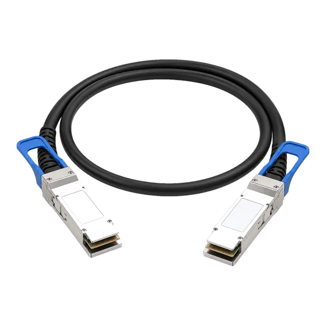
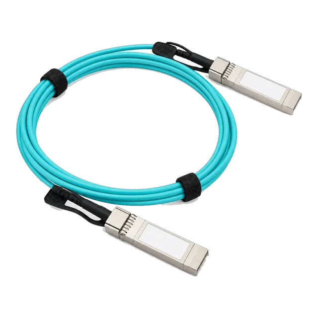
Direct attach copper cables deliver near-zero latency, consume under 0.1 W per port, and cut intra-rack connection costs by half, making them the standard physical layer interconnect across top-of-rack switch-to-server runs under 5 metres.
01What is a DAC cable and how does it function?
A dac cable is a factory-terminated twinaxial copper cable assembly fitted with transceiver-style connectors at both ends that plugs directly into switch and server ports without optical conversion. Operating entirely in the electrical domain, a direct attach cable transfers high-speed serial data over shielded balanced copper lines, bypassing the laser transmitters, photodiode receivers, and optical alignment fixtures found in traditional optical transceivers. By eliminating optical-to-electrical conversions, these assemblies minimise latency, reduce system power draw to nominal levels, and eliminate the optical insertion loss typical of structured cabling plants.
Internally, a twinaxial cable consists of one or more shielded differential pairs. Each pair comprises two solid or stranded silver-plated copper conductors insulated by a foamed dielectric, wrapped in an aluminised polyester shield, and bound with a drain wire. The connector ends contain a small printed circuit board (PCB) carrying EEPROM chips that store device identity, operational parameters, and serial data formatted according to industry standards like SFF-8024 and SFF-8472. Modern facilities deploy a DAC & AOC cable architecture in top-of-rack (ToR) layouts to achieve reliable intra-rack connectivity without the capital expense and power footprint of short-reach optical transceivers.
02Passive versus active direct attach copper dac cables
Passive direct attach copper dac cables contain no active signal conditioning components in their backshells, passing the high-speed differential signal directly from the host silicon through the copper twinax conductors. Because passive assemblies rely entirely on the host physical layer (PHY) or serialiser/deserialiser (SerDes) to perform continuous time linear equalisation (CTLE), feed-forward equalisation (FFE), and decision feedback equalisation (DFE), their reach is constrained by high-frequency attenuation. Passive cables typically achieve maximum link lengths between 1 metre and 5 metres depending on the signalling rate and conductor gauge.
Active copper direct attach assemblies incorporate an integrated driver, equaliser, or retimer chip inside the connector housing. These active silicon circuits boost and reshape high-frequency signals before they enter the copper conductors, or re-amplify degraded signals at the receiver before delivering them to the host port. Active DACs extend link reaches up to 7 to 10 metres at 10G or 25G data rates and allow thinner, more flexible conductors. However, active assemblies introduce added latency (especially when retimers with clock and data recovery are used), consume 0.5 W to 1.5 W per termination end, and introduce additional failure points compared to purely passive copper.
03How copper direct attach compares to optical transceivers and AOCs
Selecting between copper direct attach assemblies, active optical cables (AOC), and discrete transceiver-fibre links involves evaluating power budgets, channel latency, physical bend radii, and port capital expenditure. Where links remain within the same equipment cabinet or between adjacent racks, copper provides decisive operational savings. For links exceeding 5 to 7 metres, engineers turn to optical assemblies such as the High Speed 10G SFP+ AOC Active Optical Cable or modular transceivers operating over multimode optical fiber.
| Metric | Passive DAC Cable | Active Optical Cable (AOC) | Optical Transceiver + Patch Cable |
|---|---|---|---|
| Transmission Medium | Twinaxial Copper | Multimode Optical Fibre | Multimode (OM4) or Single-Mode (G.652.D) |
| Maximum Practical Reach | 3 m to 5 m (rate dependent) | 30 m to 100 m | 100 m (SR4) to 10 km+ (LR4) |
| Power Consumption (per end) | < 0.1 W | 0.6 W to 1.5 W | 1.0 W to 4.5 W |
| Link Latency | ~4.5 ns per metre (propagation only) | ~5 ns/m + 10 to 50 ns DSP/CDR | ~5 ns/m + 10 to 50 ns DSP/CDR |
| Relative Cost Factor | 1.0× (Baseline) | 2.5× to 3.5× | 4.0× to 8.0× |
| Bulk and Cable Diameter | Thick, heavy (AWG 26–30) | Thin, lightweight (2.0–3.0 mm) | Lightweight (1.6–2.0 mm per duplex leg) |
| Immunity to EMI | Moderate to High (Shielded) | Complete (Dielectric core) | Complete (Optical path) |
For an architectural comparison of optical and copper approaches inside the access layer, review our practical analysis on DAC or AOC RFQ specifications.
04Form factors across 10G, 25G, 40G, and 100G networks
Network form factors define the physical chassis receptacle, electrical pinout, and thermal dissipation interface governing the dac cable. In 10 Gigabit Ethernet environments, the SFP+ (Small Form-factor Pluggable Plus) interface under SFF-8431 carries a single differential transmit and receive pair operating at 10.3125 Gbps. As enterprise data centres moved to 25GbE architectures, SFP28 retained the identical mechanical footprint while adopting IEEE 802.3by electrical specifications to push line rates to 25.78125 Gbps per channel over a single lane.
Higher throughput aggregation relies on multi-channel form factors. The QSFP+ (Quad Small Form-factor Pluggable Plus) design carries four parallel channels at 10 Gbps to achieve 40GbE under IEEE 802.3ba, using connectors defined by SFF-8436. The QSFP28 evolution maintains this mechanical outline under SFF-8665, handling four 25G lanes to deliver 100GbE per IEEE 802.3bm. Modern aggregation nodes deploy factory-certified links such as the 100G QSFP28 to QSFP28 Passive Direct Attach Copper Cable to connect spine switches directly to leaf nodes or high-performance compute clusters without optical overhead.
05Breakout direct attach cable configurations for switch fabric aggregation
A breakout direct attach cable maps a multi-lane, high-density host port to multiple discrete lower-speed endpoints using a physical fan-out assembly. Commonly deployed configurations include 40G QSFP+ splitting into four individual 10G SFP+ legs, and 100G QSFP28 dividing into four 25G SFP28 terminations. Internally, the assembly splits the eight differential copper pairs within the quad-lane trunk shell into four separate twinaxial pairs, each terminating in a discrete single-lane plug.
Deploying breakout assemblies requires the switch host platform to support port bifurcation. Port bifurcation reconfigures the internal switch MAC and SerDes lanes to process the quad port as four independent interfaces rather than a single aggregated channel. For example, a 100G port running in 4 × 25G mode must allocate individual clocking, autonegotiation, and link monitoring routines to each sub-port. Network engineers specify breakout DACs to eliminate intermediate leaf switches, driving high-density server access ports straight from end-of-row or middle-of-row aggregation directors.
06Wire gauge AWG selection and physical reach limits
American Wire Gauge (AWG) determines the conductor cross-sectional area of the twinaxial cable, which directly dictates electrical insertion loss and mechanical stiffness. A smaller AWG number designates a thicker conductor with lower DC resistance and reduced high-frequency skin-effect attenuation, permitting longer reach at the expense of a wider outer diameter and reduced bend flexibility.
- 30 AWG: Conductor diameter ~0.25 mm; outer jacket ~4.5 mm. Best suited for ultra-short intra-rack patch runs (0.5 m to 1.5 m) where high flexibility and airflow preservation in high-density rack faces are paramount.
- 28 AWG: Conductor diameter ~0.32 mm; outer jacket ~5.5 mm. The enterprise sweet spot for 10G/25G deployments spanning 1.5 m to 3.0 m, offering balanced bend characteristics and manageable weight.
- 26 AWG: Conductor diameter ~0.40 mm; outer jacket ~6.5 mm to 8.0 mm. Required for longer 100G QSFP28 links (3 m to 5 m) or 40G links up to 7 m, where conductor cross-section must be maximised to keep total insertion loss within IEEE 802.3 limits.
Choosing an unnecessarily thick AWG creates mechanical strain on switch cages and obstructs exhaust thermal airflow, while an undersized gauge causes bit errors and dropped packets due to severe high-frequency channel loss.
07Insertion loss, channel budget, and signal integrity mechanics
Signal integrity across copper interconnects is governed by frequency-dependent attenuation, dielectric absorption, and impedance mismatches. As signal speeds escalate from 10G NRZ (5.156 GHz Nyquist frequency) to 25G NRZ (12.89 GHz Nyquist) and 56G PAM4 (13.28 GHz Nyquist), skin effect forces alternating electrical current to flow exclusively through the outer perimeter of the copper conductor, sharply driving up effective resistance.
IEEE 802.3by (25G) and IEEE 802.3bj/cd (100G) establish rigorous channel operating margin (COM) parameters and insertion loss budgets. To pass physical layer compliance, the maximum total channel insertion loss between the host MAC silicon outputs through the connector, PCB traces, and copper assembly must not exceed specific attenuation limits at the Nyquist frequency:
- IEEE 802.3by 25GBASE-CR: Channel insertion loss must remain below 15.5 dB at 12.89 GHz for CA-25G-L (long passive links up to 5 m) and below 8.0 dB for CA-25G-S (short passive links up to 3 m).
- IEEE 802.3bj 100GBASE-CR4: Total insertion loss through the cable assembly must not exceed 22.48 dB at 12.89 GHz between mating test fixtures.
Excessive insertion loss reduces signal eye height and width, making it impossible for the receiver's equalisers to distinguish between valid binary or PAM4 symbol transitions without triggering high bit error rates (BER).
08Worked calculation: channel loss budget for a 25G ToR dac network link
To verify whether a passive dac network cable will operate reliably without uncorrectable errors, an engineer must calculate the total channel insertion loss against the IEEE 802.3by specification limit. The following calculation assesses a top-of-rack link between a switch and a compute server using a 3-metre 28 AWG passive SFP28 cable.
Given Parameters:
- Host switch internal PCB trace loss ($L_{\text{switch}}$): 3.2 dB at 12.89 GHz
- Host server internal PCB trace loss ($L_{\text{server}}$): 3.8 dB at 12.89 GHz
- SFP28 Host connector pair insertion loss ($L_{\text{conn}}$, two mated interfaces): 1.5 dB total (0.75 dB per connector)
- Twinax cable attenuation for 28 AWG at 12.89 GHz ($A_{\text{cable}}$): 2.4 dB per metre
- Cable assembly internal paddle card PCB loss ($L_{\text{pcb}}$, two ends): 0.8 dB total
- Cable length ($l$): 3.0 metres
Step 1: Calculate the cable assembly insertion loss ($L_{\text{assembly}}$):
$$L_{\text{assembly}} = (A_{\text{cable}} \times l) + L_{\text{pcb}} = (2.4 \text{ dB/m} \times 3.0 \text{ m}) + 0.8 \text{ dB} = 7.2 \text{ dB} + 0.8 \text{ dB} = 8.0 \text{ dB}$$
Step 2: Calculate the total channel loss ($L_{\text{total}}$):
$$L_{\text{total}} = L_{\text{switch}} + L_{\text{conn}} + L_{\text{assembly}} + L_{\text{server}} = 3.2 + 1.5 + 8.0 + 3.8 = 16.5 \text{ dB}$$
Evaluation: Under IEEE 802.3by CA-25G-L, the maximum supported insertion loss from the switch PHY silicon to the server PHY silicon is 16.5 dB (budget includes host traces). This link operates precisely at the threshold margin. If the deployment runs in an un-FEC or low-capability SerDes mode, signal integrity will degrade. To ensure long-term stability and margin for temperature-induced loss increases (copper attenuation rises approximately 0.4% per °C), the engineer should upgrade the cable to 26 AWG (attenuation ~1.8 dB/m, dropping cable loss to 6.2 dB and total loss to 14.7 dB, yielding an operational safety margin of 1.8 dB).
09Forward error correction (FEC) requirements across 25G and 100G links
Forward Error Correction (FEC) algorithms detect and correct bit errors at the physical layer, transforming marginally acceptable electrical signals into virtually error-free data streams. For 10GBASE-CR links, raw bit error rates operate below $10^{-12}$ without forward error correction. However, at 25G and 100G serial rates, high-frequency signal degradation across copper requires FEC to achieve acceptable frame loss rates.
Under IEEE 802.3by and 802.3bm, hosts support three distinct FEC operational states:
- No FEC: Operates with zero algorithm-induced latency. Limited strictly to ultra-short passive copper channels (typically < 1 m) with exceptionally clean eye diagrams.
- BASE-R (Firecode / FC-FEC): Specified in IEEE 802.3 Clause 74. Adds approximately 80 to 90 ns of system latency while offering light error-correction performance. Primarily used in legacy 10G systems or 25G links under 3 metres.
- Reed-Solomon (RS-FEC): Specified in IEEE 802.3 Clause 91 (RS(528, 514) for 25G/100G NRZ; RS(544, 514) for PAM4). Adds approximately 250 ns of latency, but corrects up to 7 symbol errors per 528-symbol codeword, enabling robust operation on 3 m to 5 m copper links even when raw bit error rates approach $10^{-5}$.
Both endpoints on a link must have matching FEC settings. A common cause of a dead link between switches from different vendors using a direct attach cable is an auto-negotiation failure that sets RS-FEC on one end and No-FEC or FC-FEC on the other.
10Power consumption, cooling, and operational expense benefits
Passive direct attach copper assemblies consume zero milliwatts of direct operating power because they require no internal optical drivers or DSP silicon. The only power consumed is the small driving power drawn by the switch PHY's output stage, which typically remains below 0.1 W per port. In contrast, 10GBASE-SR optical transceivers consume approximately 1.0 W, 10GBASE-T copper RJ45 transceivers consume 2.0 W to 3.0 W, and 100G QSFP28 optical modules draw 3.5 W to 5.0 W per side.
In a standard 42U rack housing 40 compute servers, each connected to twin redundant top-of-rack switches via dual-port interfaces, 160 switch and network interface card (NIC) ports are populated. Implementing 10GBASE-T RJ45 modules across 160 ports at 2.5 W per port creates a parasitic thermal load of 400 W inside that single rack cabinet. Replacing those connections with passive SFP+ DAC cables reduces interconnect power draw to under 16 W total. Over a five-year equipment lifespan, eliminating that 384 W continuous load reduces direct power consumption by approximately 16,800 kWh per rack. Factoring in data centre power usage effectiveness (PUE) cooling ratios, copper direct attach delivers significant operational cost reductions.
11Cable management, bend radius, and rack design rules
Proper mechanical handling preserves the electrical geometry of the twinaxial lines within a dac cable. The characteristic impedance of a differential pair depends strictly on the physical distance between the two copper conductors and the uniformity of the surrounding dielectric foam. When an installer pinches, crushes, or excessively bends a copper cable, the dielectric core compresses, altering conductor spacing and inducing severe impedance discontinuities that generate signal reflections and bit errors.
Installers must strictly adhere to physical installation constraints:
- Minimum Bend Radius: Maintain a minimum static bend radius of 5 times the cable outer diameter for single-pair cables (SFP+/SFP28), and 10 times the outer diameter for multi-pair assemblies (QSFP+/QSFP28). For a 26 AWG QSFP28 cable measuring 8 mm in diameter, the bend radius must never fall below 80 mm.
- Vertical Strain Relief: Heavy 100G bundles running downward from a ToR switch create significant downward shear on the switch transceiver cages. Secure copper bundles to vertical cable managers every 300 to 450 mm to distribute physical weight.
- Velcro Over Zip Ties: Never use plastic zip ties on high-speed copper twinax. Ratchet-tightened zip ties crush the jacket and deform the internal differential pairs. Use wide, soft hook-and-loop fabric straps pulled only to snug tension.
12Host EEPROM coding, MSA compliance, and multi-vendor matching
Interoperability across enterprise switching fabrics depends on the serial EEPROM memory map defined by the Multi-Source Agreement (MSA). SFF-8472 governs 2-wire electrical memory mapping for SFP devices, while SFF-8636 outlines management interfaces for 4-lane QSFP modules. Modern switch operating systems inspect this memory upon insertion to read vendor names, part numbers, revision levels, serial identifiers, and checksum hashes before enabling the port PHY transmitters.
Enterprise host platforms often implement proprietary vendor verification algorithms. If the EEPROM checksum or vendor OUI fails internal security checks, the switch places the port into an "err-disabled" or "unsupported transceiver" state. MARS manufactures MSA-compliant assemblies programmed with custom vendor-specific microcode, allowing seamless link training on switch fabrics from major manufacturers. For deep background on how EEPROM registers function, consult our guide to transceiver coding and host EEPROM compatibility.
13Troubleshooting physical link and packet loss issues on copper DACs
When a direct attach copper link fails to achieve frame sync or suffers intermittent cyclic redundancy check (CRC) errors, systematic physical layer isolation identifies the root failure without guesswork.
- Inspect Port Link Status and Vendor Warnings: Check the host command-line interface (CLI) for transceiver detection. If the interface shows "unsupported transceiver" or fails to read internal EEPROM parameters, verify that the cable's microcode matches the host requirements.
- Verify Speed and Auto-Negotiation Settings: Auto-negotiation across copper twinax can fail between differing PHY implementations. Lock both the switch and server NIC ports manually to the target line rate (e.g., forced 25G full-duplex) to eliminate signalling mismatch.
- Audit Forward Error Correction Modes: Mismatched FEC states represent the most frequent operational failure on 25G and 100G links. Ensure both endpoints explicitly match (e.g., both set to `fec rs` or both set to `fec off`). Check the interface error counters: an elevating count of uncorrectable FEC codewords indicates physical channel degradation, whereas correctable FEC errors confirm the algorithm is successfully clearing channel noise.
- Test Physical Cable Routing and Pin Damage: Remove the connector and inspect the gold PCB contact pads with an optical loupe for scratches, pitting, or carbon buildup. Verify that the cable is not bent beyond its minimum radius along rack mounting rails. Swap the cable with a known-good assembly of a thicker gauge (e.g., swap 30 AWG for 26 AWG) to determine whether insertion loss limits are being breached.
14Procurement checklist for specifying direct attach copper dac cables in RFQs
Engineers and procurement managers should use this concrete checklist when preparing a Request for Quotation (RFQ) for high-density copper cabling to prevent delivery of incompatible gauges, unapproved lengths, or locked transceivers.
| Specification Criterion | Requirement Options to Specify | Engineering Purpose |
|---|---|---|
| Connector Type (End A / End B) | SFP+ / SFP28 / QSFP+ / QSFP28 / Breakout | Defines physical form factor and switch port mating. |
| Data Rate | 10GbE / 25GbE / 40GbE / 100GbE | Determines SerDes signalling rate and physical tuning. |
| Cable Type | Passive (standard) / Active (longer reach) | Eliminates unwanted active retimer latency and power. |
| Cable Length (metres) | 0.5 m / 1.0 m / 2.0 m / 3.0 m / 5.0 m | Avoids excess coiled slack or over-tensioned runs. |
| Conductor Gauge (AWG) | AWG 30 / AWG 28 / AWG 26 | Guarantees channel loss stays within IEEE margins. |
| Jacket Rating | LSZH (Low Smoke Zero Halogen) / PVC / OFNP | Satisfies local building codes and facility fire safety. |
| EEPROM Host Coding | Vendor-specific dual coding (e.g., End A: Switch, End B: Server) | Ensures plug-and-play port recognition without CLI lockouts. |
| FEC Capability Compliance | IEEE 802.3 Clause 74 (FC-FEC) / Clause 91 (RS-FEC) | Guarantees low BER on 25G and 100G line rates. |
To verify overall procurement practices across all optical and physical layers, reference our full optical networking procurement checklist.
15How to select and deploy the correct DAC cable for your network topology
Deploying copper direct attach assemblies within your network requires balancing port speed, physical inter-rack distances, host compatibility, and cable mechanical characteristics. For top-of-rack deployments within a single 42U cabinet, passive SFP28 or QSFP28 cables between 1 metre and 3 metres using 28 AWG or 30 AWG deliver the best blend of low insertion loss, reduced airflow blockage, and zero power consumption. When spanning adjacent racks or running down to end-of-row cabinets, verify whether total distance exceeds 5 metres; if so, transition immediately to active optical cables or short-reach optical transceivers to avoid signal degradation.
Shanghai Mars Industrial Co., Ltd. (brand MARS) supplies fully tested, MSA-compliant passive and active DAC assemblies across 10G, 25G, 40G, and 100G architectures. Every assembly is custom-coded and verified on host platforms to ensure error-free link training and complete FEC compliance upon installation. Contact our technical team at inquiry@optical-module-factory.com, connect on WhatsApp at +86 176 2154 1688, or use our direct contact page to review link budgets and source high-density interconnects for your upcoming infrastructure deployment.
16Frequently asked questions
What is the maximum length of a passive DAC cable?
The practical maximum length for a passive direct attach copper cable is 5 metres at 10G and 25G rates, and up to 3 to 5 metres at 100G depending on wire gauge. Beyond 5 metres, high-frequency attenuation exceeds standard IEEE 802.3 channel budgets, requiring active electronics or optical fibre.
Can I connect different switch brands using one DAC cable?
Yes, but only if the cable assembly features dual-vendor EEPROM coding. Because a DAC has two independent connector ends, reputable suppliers can program End A with microcode compatible with one switch vendor, while End B is coded to match a different switch or server NIC manufacturer.
Why is RS-FEC required on 25G and 100G DAC cables?
Reed-Solomon Forward Error Correction (RS-FEC) is required because 25 Gbps electrical signals experience significant high-frequency attenuation across copper twinax. RS-FEC detects and corrects burst symbol errors at the receiver, allowing the physical link to operate reliably at an effective bit error rate below 10^-12 despite degraded raw signals.
Does a passive DAC cable consume switch power?
A passive DAC cable contains no active internal silicon components and draws virtually zero power from the switch transceiver port, typically under 0.1 W. This contrasts with optical transceivers and active optical cables that consume between 1.0 W and 5.0 W per termination point.
What is the difference between AWG26, AWG28, and AWG30 DAC cables?
AWG denotes copper conductor thickness. AWG30 has the thinnest wire, making it flexible and ideal for short runs under 1.5 metres. AWG26 has the thickest conductor with the lowest electrical attenuation, enabling longer reaches up to 5 metres, but it is stiffer and heavier to manage in racks.
Can I plug a 10G SFP+ DAC cable into an SFP28 port?
Most SFP28 switch ports support backwards compatibility and can accept a 10G SFP+ DAC cable, provided the switch port's operating speed is manually configured or auto-negotiates down to 10 Gbps. However, the link will operate strictly at the 10G rate, not 25G.
Technical review note: confirm model-specific specifications with the product datasheet and the intended host documentation. Product images and application photographs are illustrative.
Discuss this with our team