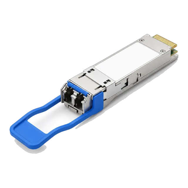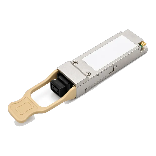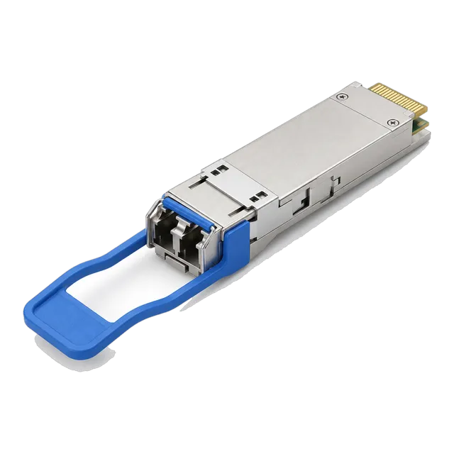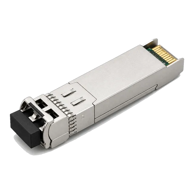
Quad Small Form-factor Pluggable transceivers aggregate four independent electrical lanes into high-density optical interfaces, requiring precise link-budget calculations, SFF-8636 EEPROM compatibility verification, and proper MPO or duplex LC physical plant planning.
01What is a QSFP transceiver and how does the architecture operate?
A qsfp transceiver (Quad Small Form-factor Pluggable) is a compact, hot-pluggable optical or electrical module designed to transmit four independent channels of data simultaneously across high-density network links. Standardised by the Small Form Factor Multi-Source Agreement (SFF MSA) committee under specifications such as SFF-8436 and SFF-8636, each qsfp module replaces four individual SFP or SFP+ ports with a single mechanical interface, quadrupling port density on switch line cards. Inside the physical enclosure, the module incorporates a 38-pin edge connector for the host electrical interface, a multi-channel transmit optical sub-assembly (TOSA), a multi-channel receive optical sub-assembly (ROSA), and an onboard microcontroller managing the two-wire management interface. Electrical signals received from the host serializer/deserializer (SerDes) are retimed, amplified, and converted into optical pulses by an array of directly modulated lasers (DML), vertical-cavity surface-emitting lasers (VCSEL), or electro-absorption modulated lasers (EML). By combining four serial lanes into a unified form factor, the qsfp transceiver provides the baseline physical interconnect for spine-and-leaf fabrics in modern enterprise and telecommunications facilities.
02QSFP transceiver evolution: QSFP, QSFP+, QSFP28, and QSFP-DD compared
The mechanical footprint defined by early quad form factors has evolved across four primary generations by scaling lane transmission rates rather than physical width. The initial QSFP specification operated at 1 Gb/s per lane, yielding 4 Gb/s aggregate throughput across four lanes. This was rapidly succeeded by QSFP+, standardised under SFF-8436 and IEEE 802.3ba, which raised the electrical lane rate to 10.3125 Gb/s to support 40GBASE Ethernet and 4x14 Gb/s FDR InfiniBand. QSFP28 subsequently advanced the architecture to 100 Gb/s by utilising four 25.78125 Gb/s channels under IEEE 802.3bm, retaining the same physical dimensions (18.35 mm width by 8.5 mm height) and backward mechanical compatibility. For 400 Gb/s and 800 Gb/s topologies, QSFP Double Density (QSFP-DD) extends the casing depth to house an eight-lane electrical contact structure utilising 50 Gb/s PAM4 (4-level Pulse Amplitude Modulation) signalling under IEEE 802.3cd and IEEE 802.3ck. Systems running 40G QSFP+ interfaces often bridge directly into QSFP28 spine architectures through our 40G QSFP+ optical modules or higher-speed 100G QSFP28 transceivers.
03Electrical and optical pinout mapping under SFF-8436 and SFF-8636
The electrical interface of a standard QSFP transceiver comprises 38 edge connector pins mapped to provide power, low-speed management signals, and four differential transmit and receive pairs. High-speed data paths run over pins 36/37 (Tx1+/Tx1-), 33/34 (Tx2+/Tx2-), 14/15 (Tx3+/Tx3-), and 17/18 (Tx4+/Tx4-) for transmission, with matched differential pairs handling receiver duties on pins 2/3 (Rx1+/Rx1-), 5/6 (Rx2+/Rx2-), 22/23 (Rx3+/Rx3-), and 25/26 (Rx4+/Rx4-). Low-speed control lines operate over open-drain signals: Pin 8 (ModPrsL) grounds on the host to indicate transceiver presence; Pin 27 (ModSelL) enables host I2C communication over Pin 9 (SCL) and Pin 10 (SDA); Pin 28 (IntL) asserts low to signal interrupts such as alarm conditions; and Pin 31 (ResetL) permits the host to reboot the internal module microcontroller without cycling chassis DC power. Power delivery is segmented across Pin 10 (+3.3V Host receiver), Pin 20 (+3.3V Transmitter), and Pin 29 (+3.3V Receiver) to isolate noise sensitive optoelectronics from digital rail interference.
04Optical connector options: MPO parallel optics versus duplex LC WDM
Physical connectivity on a QSFP transceiver is dictated by the internal optical multiplexing architecture, categorised into parallel multi-fibre connectors or duplex wavelength division multiplexing (WDM) interfaces. Short-reach multi-mode transceivers, such as 40GBASE-SR4, employ an MPO-12 (Multi-fibre Push-On) connector interface utilising an 8-fibre optical ribbon array where the outer four fibres transmit and the opposite four receive, leaving the central four positions unpopulated. In contrast, long-reach single-mode designs integrate an internal optical multiplexer and de-multiplexer, enabling all four lanes to travel over a single strand per direction through an industry-standard duplex LC interface. Deploying parallel MPO connectivity requires careful discipline regarding connector gender and polarity rules, as explored in our guide to MPO/MTP polarity and Base-8 field practice. For single-mode infrastructure where pulling additional ribbon cable is cost-prohibitive, selecting a duplex LC module leverages existing structured cabling while preserving raw bandwidth.
0540G QSFP+ interface variants and optical power budgets
Optical reach across 40 Gb/s deployments depends on laser wavelength, modal dispersion limits, and receiver sensitivity specifications defined under IEEE 802.3ba. Multimode short-reach applications rely on 850 nm VCSEL arrays, while long-reach networks utilise four distinct wavelengths arranged across the Local Wavelength Division Multiplexing (LWDM) or Coarse WDM (CWDM) grid centered near 1310 nm. Transceiver power budgets represent the differential between minimum guaranteed transmitter launch power and the receiver sensitivity threshold at a bit error ratio (BER) of 10-12 before forward error correction. Modules such as the 40G QSFP+ SR4 850nm 100-300m Multimode Transceiver address campus backbones, whereas single-mode variants like the 40G QSFP+ LR4 1310nm 10km Module cover building-to-building interconnections.
| Standard Designation | Fibre Medium | Wavelength (nm) | Connector Type | Max Distance (m) | Min Tx Power (dBm) | Rx Sensitivity (dBm) |
|---|---|---|---|---|---|---|
| 40GBASE-SR4 | MMF (OM4) | 850 | MPO-12 (Base-8) | 100 / 150 | -7.6 (per lane) | -9.5 (per lane) |
| 40GBASE-LR4 | SMF (ITU-T G.652) | 1271, 1291, 1311, 1331 | Duplex LC | 10,000 | -7.0 (per lane) | -13.7 (per lane) |
| 40GBASE-ER4 | SMF (ITU-T G.652) | 1271, 1291, 1311, 1331 | Duplex LC | 40,000 | -2.7 (per lane) | -21.2 (per lane) |
06100G QSFP28 interface variants: SR4, CWDM4, LR4, and single-lambda optics
The 100 Gb/s QSFP28 architecture increases throughput by driving each of the four optical lanes at 25.78125 Gb/s, aligning with modern spine-leaf and inter-rack data centre topologies. IEEE 802.3bm defines 100GBASE-SR4 for MPO multimode links up to 100 metres over OM4, while long-reach variants use the duplex LC interface to traverse single-mode glass. For enterprise and metropolitan networks, the 100G QSFP28 LR4 10km Single-Mode Module delivers carrier-grade reach across ITU-T G.652 single-mode fibre using an integrated LAN-WDM multiplexer. Mid-reach environments often rely on CWDM4 MSA specifications, which discard optical hermetic packaging to lower unit costs over 2 km spans. Newer single-lambda 100G optics (such as 100GBASE-DR1 and FR1) incorporate an onboard Digital Signal Processor (DSP) gearbox that aggregates the four 25G electrical host lanes into a single 100 Gb/s PAM4 optical carrier, substantially reducing optical component count.
For a detailed breakdown of architectural differences across these 100G standards, review our engineering comparison on QSFP28 transceiver optics and architecture.
07Link budget calculation for a 40GBASE-LR4 single-mode link
A reliable optical link calculation ensures that the optical channel insertion loss does not exceed the available power budget under worst-case transmitter degradation and connector contamination. Under IEEE 802.3ba Table 87-8, a compliant 40GBASE-LR4 qsfp module specifies a minimum average launch power per lane of -7.0 dBm and a maximum receiver sensitivity of -13.7 dBm per lane. Subtracting the receiver sensitivity from the minimum launch power yields an available power budget of 6.7 dB.
To evaluate a prospective 8.5 km link run across single-mode glass (ITU-T G.652.D) with four intermediate patch panels, use the following calculation model:
- Fibre Cable Attenuation: 8.5 km × 0.35 dB/km (at 1310 nm) = 2.975 dB
- Connector Losses: 6 mated LC connector pairs × 0.35 dB (IEC 61753 grade B/2 limit) = 2.10 dB
- Fusion Splice Losses: 4 fusion splices × 0.05 dB = 0.20 dB
- Total Channel Insertion Loss: 2.975 dB + 2.10 dB + 0.20 dB = 5.275 dB
- Operational Power Margin: 6.70 dB - 5.275 dB = 1.425 dB
Because the resulting operational power margin of 1.425 dB exceeds the standard telecommunications safety requirement of 1.0 dB, this 8.5 km optical path will operate reliably over temperature and component ageing cycles. Detailed parameters can be modelled across varying environments using our interactive optical link budget calculator.
08Understanding breakout modes: 40G to 4x10G and 100G to 4x25G
Breakout capability allows a high-density qsfp optics port on a aggregation switch to operate as four individual low-speed client ports, eliminating stranded switch capacity. Because a 40G QSFP+ port internally provides four 10.3125 Gb/s SerDes channels, setting the switch operating mode to channelised or breakout mode maps those electrical channels into four independent 10GBASE-SR or 10GBASE-LR interfaces. For optical multi-mode distribution, this is achieved using an MPO-to-4x-duplex-LC fan-out patch cable, where the four transmit and four receive fibres of the MPO connector are terminated into four distinct LC pairs connected to standard 10G SFP+ transceivers. Similarly, a 100G QSFP28 port can be broken out into four 25G SFP28 links using our high-speed multi-rate transceiver solutions, provided the host switch ASIC supports independent clocking and lane negotiation for each SerDes sub-channel.
09Thermal management and power dissipation classes in dense chassis
Thermal performance determines whether a high-density switch backplane can sustain line-rate performance without thermal throttling or optoelectronic degradation. Under SFF-8679 and SFF-8436, QSFP modules are grouped into discrete power dissipation classes: Class 1 (up to 1.5 W), Class 2 (up to 2.0 W), Class 3 (up to 2.5 W), and Class 4 through 7 (scaling from 3.5 W up to 5.0 W for long-reach or amplified designs). While standard 40GBASE-SR4 multi-mode modules generally consume less than 1.5 W, single-mode CWDM4 and LR4 modules dissipate between 2.5 W and 3.5 W due to the thermoelectric cooler (TEC) or laser driver circuitry. When deploying a full chassis line card with 36 contiguous QSFP ports, overall optical thermal load can exceed 120 W in a single rack unit. Network architects must ensure that chassis fan trays supply sufficient cubic feet per minute (CFM) of airflow and match module airflow directions (front-to-back or back-to-front) to host system cooling paths.
10Digital diagnostic monitoring and EEPROM memory maps
Digital Diagnostic Monitoring (DDM), also referred to as Digital Optical Monitoring (DOM), allows network operators to inspect real-time physical layer telemetry through an I2C serial bus mapped according to SFF-8636. The internal non-volatile EEPROM memory architecture is partitioned into a 128-byte Lower Memory page (accessible directly at I2C address A0h) and multiple 128-byte Upper Memory pages selected via Byte 127. The Lower Page reports real-time analog monitoring values, interrupt flags, and channel monitor masks, tracking operating temperature, internal supply voltage, per-channel laser bias current, transmit optical power (Tx Power), and received optical power (Rx Power). Upper Page 00h stores static device identification, including MSA compliance bytes, vendor name, serial number, date codes, and link reach capabilities. Upper Page 02h and 03h house user-programmable registers, alarm/warning threshold parameters, and advanced FEC status bits. Real-time telemetry monitoring prevents catastrophic link drops by alerting management platforms when optical loss approaches receiver sensitivity limits.
11Host platform compatibility and EEPROM vendor coding
Switch operating systems validate inserted transceivers by reading the vendor identification, part number, and cryptographic checksum registers located in Upper Page 00h of the SFF-8636 memory space. If a host platform detects that the vendor name or security hash does not match its internal whitelist, it will disable the transmitter, set the interface state to 'err-disabled', and log an unsupported transceiver exception. MARS engineers configure each qsfp module with target-specific microcode, matching the precise checksum calculation, device identifier, and extended vendor-specific blocks required by each host switch manufacturer. Because transceivers adhere strictly to electrical and optical specifications across IEEE 802.3 and SFF standards, resolving this firmware layer ensures flawless interoperability without requiring costly vendor-branded hardware. For an in-depth explanation of how microcode verification operates, read our technical brief on transceiver coding, EEPROM maps, and host support.
12Comparing copper DAC, AOC, and optical transceivers for intra-rack links
Choosing between Direct Attach Copper (DAC), Active Optical Cables (AOC), and discrete QSFP transceivers requires balancing interconnect distance, power consumption, latency, and capital expenditure across intra-rack and inter-rack scenarios. Passive DAC cables provide the lowest latency (under 10 nanoseconds) and near-zero power dissipation (under 0.1 W per termination), but their practical length is strictly limited by skin-effect attenuation to 3 metres at 100 Gb/s (QSFP28) and 5 metres at 40 Gb/s (QSFP+). AOC cables integrate fixed optical transceivers with non-detachable multimode fibre assemblies, consuming approximately 1.5 W to 2.2 W per end while extending spans up to 100 metres with thin, flexible cable profiles. Discrete optical transceivers paired with structured cabling offer the greatest flexibility, permitting rapid field reconfiguration, long reach, and patch panel cross-connect integration, albeit at higher initial acquisition cost and marginally higher power consumption per port.
| Interconnect Type | Max Distance (m) | Power Per End (W) | Latency (ns) | Cable Bend Radius (mm) | Primary Use Case |
|---|---|---|---|---|---|
| Passive Copper DAC | 3 to 5 | < 0.1 | < 10 | 35 to 50 | Same-rack Top-of-Rack to Server links |
| Active Optical Cable (AOC) | 70 to 100 | 1.2 to 2.2 | ~15 | 25 to 35 | Inter-rack switch-to-switch aggregation |
| Discrete QSFP Transceiver | 100 to 40,000 | 1.5 to 3.5 | ~15 (media dependent) | Structured Cable standard | Spine-and-leaf fabrics, campus interconnects |
13Engineering checklist for issuing a QSFP module RFQ
Procurement teams and network architects should standardise technical specifications before issuing a Request for Quotation (RFQ) to eliminate cross-compatibility issues, power envelope discrepancies, and field deployment failures. Copy and populate the following technical parameters into your bill of materials (BOM):
- Target Standard & Data Rate: e.g., 40GBASE-LR4 (41.25 Gb/s) or 100GBASE-SR4 (103.125 Gb/s).
- Form Factor: QSFP+ (SFF-8436) or QSFP28 (SFF-8665).
- Physical Optical Media: Single-mode fibre (ITU-T G.652.D) or Multimode fibre (OM4).
- Connector Interface: Duplex LC or MPO-12 (specify Base-8 pinned or unpinned).
- Nominal Wavelength: 850 nm, CWDM4 grid (1271-1331 nm), or LAN-WDM grid (1295-1309 nm).
- Link Distance Requirement: Minimum operational distance (e.g., 100 m, 2 km, 10 km, 40 km).
- Host Platform Target: Brand name, switch model, line-card part number, and operating system software release.
- Operating Temperature Range: Commercial (0°C to +70°C) or Industrial (-40°C to +85°C).
- Telemetry & Monitoring: Mandatory SFF-8636 Digital Diagnostic Monitoring (DDM/DOM) compliance.
- FEC Requirements: Clarify whether host SerDes mandates IEEE 802.3 Clause 91 RS-FEC or Clause 74 FireCode FEC.
14Deploying, inspecting, and maintaining QSFP optics in production fabrics
Maintaining high signal-to-noise ratio across multi-lane qsfp optics requires disciplined handling and strict physical layer inspection prior to mating. The eight or twelve micro-lenses of an MPO connector face, as well as the dual ceramic ferrules of LC duplex assemblies, are highly susceptible to airborne dust and oil contamination. Before inserting any patch cable into a production qsfp transceiver, inspect both connector end-faces using an optical inspection microscope compliant with IEC 61300-3-35. Dry-clean the optical ports using a dedicated 1.25 mm/2.5 mm swab or mechanical IBC click-cleaner designed for MPO/LC interfaces; never use isopropyl alcohol swabs that leave residue along ferrule guide pin sockets. When inserting the module into a switch cage, apply steady horizontal pressure until the latch mechanism clicks firmly into the cage retention tab. Monitor DDM registers immediately after link turn-up: verify that per-channel receiver optical power levels fall comfortably between the minimum sensitivity and overload thresholds. For assistance with customized firmware coding, line card validation, or bespoke link engineering, submit your network details via our technical inquiry portal.
15Frequently asked questions
Can I plug a 40G QSFP+ transceiver into a 100G QSFP28 switch port?
Yes, most 100G QSFP28 switch ports backward-support 40G QSFP+ transceivers. The host switch detects the module type via SFF-8636 EEPROM registers and clocks its SerDes down from 25 Gb/s to 10 Gb/s per lane, though you must confirm that the switch software allows port speed reconfiguration.
What is the primary difference between QSFP+ and QSFP28 transceivers?
The primary difference is data rate per electrical lane. QSFP+ transmits four 10 Gb/s channels to achieve an aggregate 40 Gb/s throughput, whereas QSFP28 transmits four 25 Gb/s channels to achieve 100 Gb/s throughput while retaining the same physical dimensions and connector envelope.
What does a Base-8 MPO connector mean for a 40G or 100G QSFP module?
A Base-8 MPO connector uses eight active optical fibres within a 12-fibre connector housing to transmit data. Four fibres carry transmit channels (Tx1-Tx4) and four fibres carry receive channels (Rx1-Rx4), leaving the middle four fibre positions dark and unused under IEEE 802.3ba and 802.3bm standards.
Why does a 40GBASE-LR4 transceiver use a duplex LC connector instead of MPO?
A 40GBASE-LR4 module integrates an internal optical multiplexer and de-multiplexer. It combines four separate CWDM wavelengths onto a single single-mode transmit fibre and separates them from a single receive fibre, enabling full 40 Gb/s operation over standard duplex LC single-mode structured cabling.
What causes an unsupported transceiver error when installing a QSFP module?
An unsupported transceiver error occurs when the host switch operating system inspects Upper Page 00h of the module EEPROM and fails to find matching vendor identification, approved part numbers, or valid checksums. MARS solves this by programming host-specific microcode into the module firmware prior to shipment.
Does a 100G QSFP28 transceiver require Forward Error Correction (FEC)?
Most 100G QSFP28 standards require Forward Error Correction to operate error-free. 100GBASE-SR4 and CWDM4 mandate IEEE 802.3 Clause 91 Reed-Solomon FEC (RS-FEC 528,514) on the host switch SerDes to correct random bit errors, whereas standard 100GBASE-LR4 operates with native uncorrected BER below 10^-12.
Technical review note: confirm model-specific specifications with the product datasheet and the intended host documentation. Product images and application photographs are illustrative.
Discuss this with our team