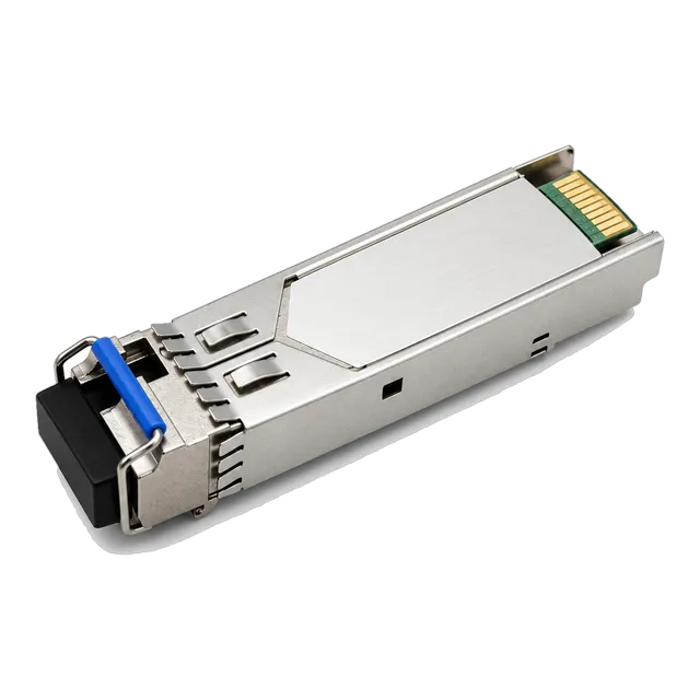
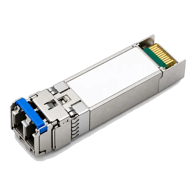
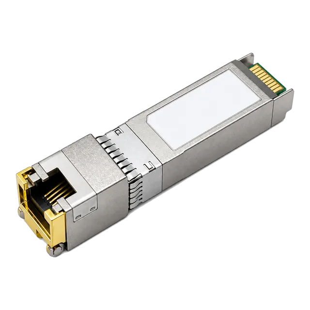
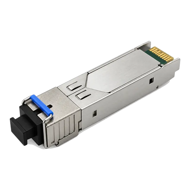
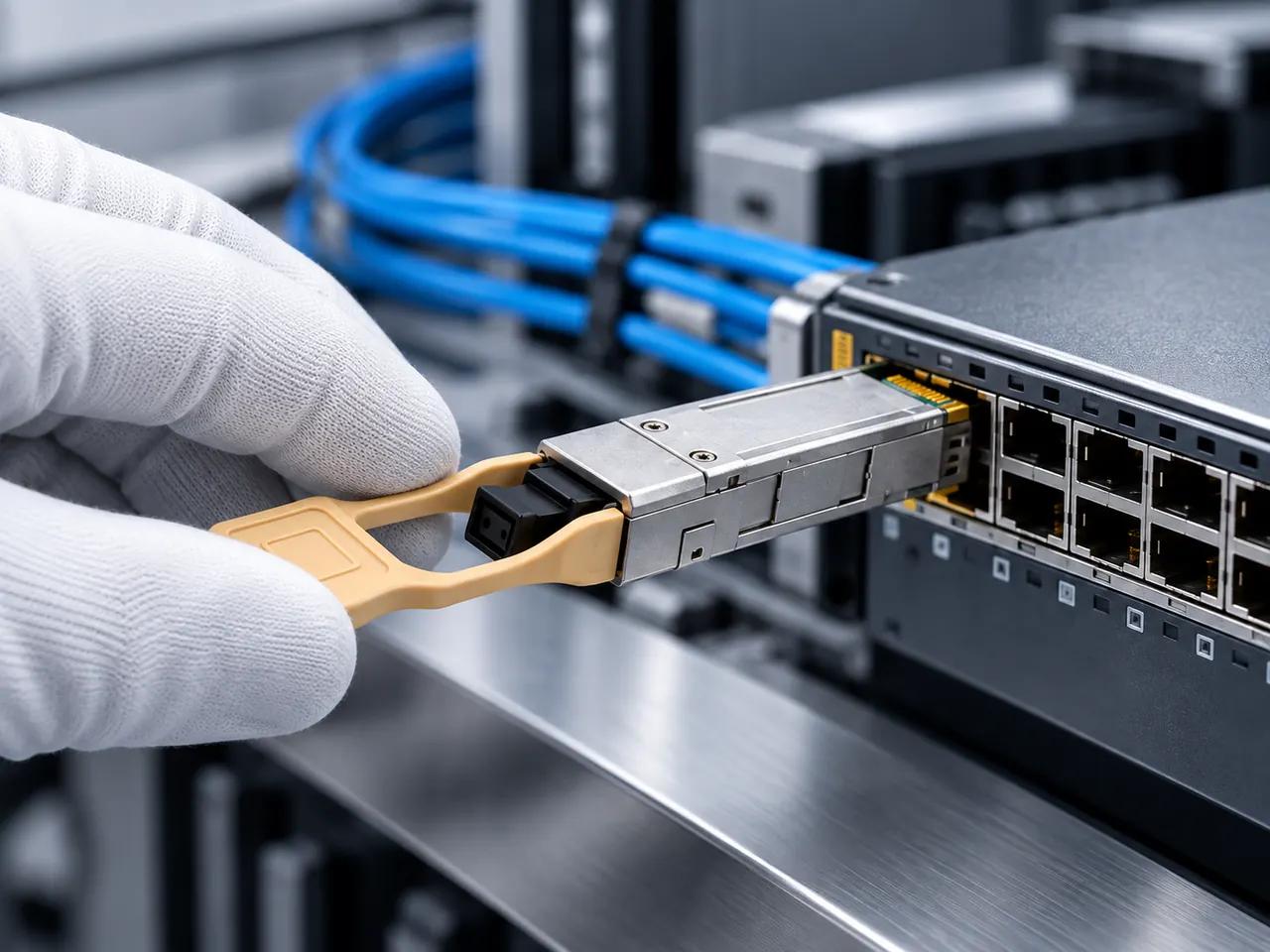
SFP transceivers primarily use LC duplex connectors for dual-fibre optics, LC simplex for bidirectional links, RJ45 for twisted-pair copper, and occasionally SC for PON or legacy single-fibre deployments.
01Which type of connectors do SFP transceivers use
SFP transceivers primarily use Lucent Connector (LC) duplex optical interfaces, Simplex LC interfaces for single-strand bidirectional optics, and Registered Jack 45 (RJ45) electrical receptacles for twisted-pair copper cabling. Answering precisely which type of connectors do sfp transceivers use depends on the physical transmission medium and module design defined by multi-source agreements (MSAs). Standard dual-fibre optical transceivers rely on the LC duplex interface because its miniature 1.25 mm ceramic ferrule fits within the compact 13.4 mm width of the SFP form factor. For single-fibre wavelength division multiplexing (WDM) links, modules use a Simplex LC receptacle. Copper-based transceivers incorporate an extended RJ45 socket designed to fit standard Category 5e, 6, or 6A patch leads.
Certain specialist telecommunications and passive optical network (PON) transceivers also utilise Subscriber Connector (SC) interfaces, although the larger 2.5 mm SC ferrule requires an extended mechanical shell that protrudes beyond the front faceplate of the host chassis. Direct-attach copper (DAC) and active optical cables (AOC) omit separable external optical connectors entirely, terminating factory-crimped electrical or optical assemblies directly inside fixed SFP transceiver shells.
02The acronym SFP and mechanical interface standards
The acronym SFP stands for Small Form-factor Pluggable, an industry-standard hot-swappable transceiver format established by the SFF Committee under specification SFF-8074i. Subsequent revisions, including SFF-8431 and SFF-8432, standardised enhanced physical dimensions and electrical interfaces for higher signalling rates while retaining the external physical envelope.
Standard SFP transceiver mechanical envelopes specify an overall module width of 13.4 mm, a height of 8.5 mm, and an inserted cage depth of 56.5 mm. Because the faceplate footprint is highly constrained, traditional data communications connectors like the SC (with its 2.5 mm ferrule) could not accommodate dual-channel transmit (Tx) and receive (Rx) paths inside a single cage. The standardization of the 1.25 mm ceramic ferrule under IEC 61754-20 enabled dual-bore receptacles, standardising the LC duplex interface as the primary optical connector across global switching platforms. For further mechanical background, review our Small Form Factor Pluggable Module guide.
03Duplex LC connectors in optical SFP transceivers
Duplex LC connectors are the standard physical interface for two-fibre optical transceivers operating over multimode and single-mode infrastructure. The duplex LC interface groups two independent 1.25 mm cylindrical ceramic ferrules within a single moulded polymer housing featuring a 6.25 mm port pitch, latching via an RJ-style push-pull retention clip defined by IEC 61754-20.
Inside the transceiver, one optical bore connects to the transmitter optical sub-assembly (TOSA), which houses a laser diode such as an 850 nm vertical-cavity surface-emitting laser (VCSEL) or a 1310 nm distributed-feedback (DFB) laser. The adjacent bore aligns directly with the receiver optical sub-assembly (ROSA), terminating at a pin-photodiode or avalanche photodiode (APD). For high-speed interconnects such as the 25G SFP28 ER 1310nm 40km single-mode module, duplex LC connectors provide precise mechanical alignment, limiting standard insertion loss to below 0.20 dB across the junction.
04Simplex LC connectors for BiDi transceivers
Simplex LC connectors are the default interface for bidirectional (BiDi) SFP transceivers that transmit and receive over a single optical fibre. Rather than dedicating separate ports to transmission and reception, BiDi modules incorporate an internal optical diplexer filter that splits different optical wavelengths inside a single optical sub-assembly (BOSA).
A typical 1.25 Gb/s single-mode BiDi link uses an upstream wavelength of 1310 nm and a downstream wavelength of 1550 nm, terminated through a single Simplex LC port. For instance, the 1.25G BiDi single-fiber SFP transceiver 1310nm/1550nm 20km operates over one ITU-T G.652 single-mode core, halving optical patch cord requirements across enterprise backbones. Detailed engineering rules for matching these wavelength pairs are explained in our bidirectional SFP wavelength pairs guide.
05SC connectors in legacy and FTTH SFP modules
SC connectors use a push-pull latching mechanism and a 2.5 mm ceramic ferrule defined by IEC 61754-4, delivering excellent mechanical durability at the cost of physical port density. Although standard SFP cages lack the width to house a duplex SC connector, single-bore SC simplex receptacles are deployed on specialised bidirectional transceivers.
In broadband fibre-to-the-home (FTTH) architectures, Gigabit Passive Optical Network (GPON) Optical Line Terminal (OLT) and Optical Network Unit (ONU) transceivers frequently feature SC receptacles to mate directly with pre-existing outside-plant passive optical splitters. Legacy metro Ethernet links also make use of units such as the 1.25G SFP BiDi optical module 20km with SC simplex interface. In these modules, the SC barrel extends outward past the switch faceplate to preserve internal circuit clearances while mating with subscriber drop cables.
06RJ45 copper interfaces in SFP and SFP+ transceivers
RJ45 copper interfaces convert the SFP electrical host bus into an 8-position 8-contact (8P8C) modular twisted-pair socket compliant with IEEE 802.3ab and IEEE 802.3an standards. Unlike optical modules that transfer light through ferrules, copper SFP transceivers contain integrated physical layer (PHY) serializer/deserializer (SerDes) chips and pulse transformers inside the pluggable casing.
Standard 1000BASE-T and 10GBASE-T transceivers, such as the 10G SFP+ copper RJ45 10GBASE-T transceiver, accept standard Cat6a and Cat7 shielded twisted-pair cables up to 30 m or 80 m depending on link negotiation modes. Because the outer dimensions of an RJ45 modular jack exceed the 8.5 mm internal height of an SFP cage, copper transceivers feature an enlarged front snout that sits external to the cage latch mechanism. Explore operational parameters in our copper SFP transceiver guide or browse our dedicated copper RJ45 SFP product family.
07SFP type distinctions: SFP, SFP+, and SFP28 optical interfaces
Each SFP type represents a progression in serial data rate, transitioning from 1.25 Gb/s (SFP) to 10 Gb/s (SFP+) and 25 Gb/s (SFP28) while retaining identical external connector dimensions. Across all three generations, the duplex LC interface remains the physical connector standard for point-to-point fibre links.
The physical connector dimensions do not change between an SFP 1000BASE-SX module and a 25GBASE-SR SFP28 module; both mate with standard LC patch cords conforming to IEC 61754-20. However, the internal electro-optical assemblies differ substantially: 25G SFP28 optical paths require tighter ferrule concentricity, controlled modal launch conditions, and high-bandwidth photodetectors capable of accommodating 25.78125 Gb/s non-return-to-zero (NRZ) signalling. While an LC duplex cable physically fits into any generation, link establishment depends on transceivers matching data rates, encoding schemes, and host clocking architectures.
08Physical polish options: UPC versus APC in SFP transceivers
SFP optical transceivers use either Ultra Physical Contact (UPC) or Angled Physical Contact (APC) ferrule end-face polishes, directly determining back-reflection performance. UPC connectors feature a slightly domed end face polished at zero degrees, yielding an optical return loss (ORL) of ≥50 dB, whereas APC connectors are polished at an 8-degree angle, forcing reflected light into the fiber cladding to achieve an ORL of ≥60 dB.
Standard duplex LC SFP modules universally employ UPC polish, identifiable by blue connector boots and receptacles. APC polish, colour-coded green, is used in single-fibre BiDi links, dense wavelength division multiplexing (DWDM) systems, and PON networks where back-reflections cause optical return loss degradation, laser instability, and transmitter noise. Never mate an APC ferrule directly with a UPC receptacle; the angled apex creates an air gap with severe optical insertion loss exceeding 4 dB and causes permanent surface scratching on both ceramic ferrules.
09Types of SFP connectors compared across performance metrics
Selecting among the types of SFP connectors requires balancing physical media compatibility, transmission reach, insertion loss budgets, and switch density. The following comparison table outlines the engineering properties of connectors encountered in modern SFP deployments.
| Connector Type | Ferrule / Contact | Polish Grade | Insertion Loss (dB) | Return Loss (dB) | Max Reach | Supported SFP Types |
|---|---|---|---|---|---|---|
| LC Duplex | 1.25 mm Ceramic | UPC (Blue) | 0.15 - 0.25 | ≥ 50 | 120 km | SFP, SFP+, SFP28 |
| LC Simplex (BiDi) | 1.25 mm Ceramic | UPC or APC | 0.15 - 0.30 | ≥ 50 (UPC) / ≥ 60 (APC) | 100 km | SFP, SFP+, SFP28 |
| SC Simplex | 2.5 mm Ceramic | UPC or APC | 0.20 - 0.35 | ≥ 50 (UPC) / ≥ 60 (APC) | 40 km | SFP (GPON, BiDi) |
| RJ45 Modular | 8P8C Phosphor Bronze | N/A (Nickel/Gold) | 0.50 - 1.50 | N/A (Cat6a Return Loss) | 100 m | SFP (1G), SFP+ (10G) |
| Direct Attach (DAC) | PCB Edge Contact | N/A (Gold plated) | Integrated | Integrated | 7 m | SFP+, SFP28 |
To view our full hardware range spanning multiple data rates and connector builds, review the 1.25G SFP transceivers portfolio.
10Calculating insertion loss and connector budget for SFP links
Calculating total connector insertion loss ensures that optical power arriving at the receiver optical sub-assembly remains within the dynamic range defined by SFF-8472 digital diagnostic monitoring (DDM). An optical power budget subtracts receiver sensitivity from minimum transmitter launch power, leaving a margin that must accommodate fibre attenuation, splice loss, and connector mating interfaces.
Consider an engineered link using a 10GBASE-LR SFP+ module operating at 1310 nm over 10 km of ITU-T G.652.D single-mode fibre:
- Transmitter Minimum Launch Power (P_tx_min): -8.2 dBm
- Receiver Sensitivity (P_rx_sens): -14.4 dBm
- Available Channel Power Budget: -8.2 dBm - (-14.4 dBm) = 6.2 dB
Next, sum the link component losses based on standard IEC 61753-1 and TIA-568 allowances:
- Fibre Attenuation: 10 km × 0.35 dB/km = 3.50 dB
- Transceiver Port Mating Connectors (2 × LC UPC): 2 × 0.25 dB = 0.50 dB
- Patch Panel Interconnects (4 × LC UPC): 4 × 0.25 dB = 1.00 dB
- Fusion Splices (2 splices): 2 × 0.05 dB = 0.10 dB
- Total Link Channel Loss: 3.50 + 0.50 + 1.00 + 0.10 = 5.10 dB
Calculate the operating optical power margin:
- Optical Margin: 6.20 dB - 5.10 dB = 1.10 dB
An operating margin of 1.10 dB meets minimum design criteria (>1.0 dB). However, if an uncleaned LC connector ferrule introduces 1.5 dB of contamination loss, the total channel attenuation rises to 6.60 dB, exceeding the budget and triggering packet loss. You can verify your channel calculations quickly using our online optical link budget calculator or read our technical guide on calculating optical link budgets.
11Inspection and cleaning standards for SFP connector interfaces
IEC 61300-3-35 defines mandatory visual pass/fail criteria for inspecting fibre optic connector end faces before plugging them into an SFP transceiver receptacle. Dust particles, skin oils, and airborne residues are microscopic; a 5 μm particulate across the 9 μm core of a single-mode LC connector can block light transmission entirely or permanently pit the mating ferrule.
The standard establishes four concentric zones on the ferrule end face:
- Zone A (Core Zone, 0 to 25 μm diameter): No scratches or defects permitted.
- Zone B (Cladding Zone, 25 to 120 μm diameter): No scratches >3 μm; defects <5 μm permitted if not touching the core.
- Zone C (Adhesive Layer, 120 to 130 μm diameter): Minor pits and chips permitted outside structural bonding points.
- Zone D (Contact Area, 130 to 250 μm diameter): Scratches and defects permitted up to 10 μm, provided they do not affect mating alignment.
Always apply a dry-clean/wet-clean process using lint-free optic wipes dampened with high-purity optical solvent, followed by a dedicated 1.25 mm push-action cleaning pen for internal SFP transceiver optical bores. Never blow compressed air directly into an SFP optical cavity; propellants deposit liquid residues across the ROSA photodiode surface.
12Common connector mating errors and troubleshooting steps
Connector mating errors in SFP transceivers stem primarily from misaligned polarity, incompatible end-face polishes, contamination, or damaged retention latches. When link status LEDs fail to illuminate, field technicians can isolate connector issues methodically using physical inspection and DDM telemetric registers.
- Verify Transmit/Receive Polarity: Duplex LC patch leads have an A-to-B crossover configuration. If the link is down, swap the individual LC simplex connectors inside the duplex clip to ensure the switch Tx port connects to the remote Rx port.
- Audit Physical Polish Matching: Ensure green LC/APC connectors are not plugged into blue LC/UPC transceivers. Inspect the mating port under a fibrescope for mechanical ferrule crush damage.
- Read DDM Rx Optical Power: Access host CLI diagnostics via MSA SFF-8472 commands. If Tx power is normal (e.g. -3 dBm) but Rx power reads below sensitivity (e.g. -40 dBm), clean both the cable ferrule and transceiver barrel.
- Check Copper RJ45 Auto-Negotiation: When using 10GBASE-T SFP+ modules, ensure the host switch port supports the negotiated speed. Some legacy SFP+ ports do not auto-negotiate to 1G or 2.5G without manual speed setting overrides.
- Test with an Optical Power Meter: Disconnect the patch cord at the local transceiver and measure incoming Rx power directly from the far-end laser to isolate backbone cable plant faults from local connector issues.
13Technical RFQ checklist for SFP transceivers and optical patch cords
Preparing a complete procurement request for SFP transceivers requires matching optical transceiver specifications directly to the mating connector standards of your cabling plant. Omitting connector details from a bill of materials frequently results in mismatched polish geometries or incompatible fibre modes. For more detailed pinout diagrams and interface schematics, refer to our comprehensive guide on SFP connector types, pinouts, and optics.
When issuing a request for quotation (RFQ), ensure your hardware specification covers these seven parameters:
- Transceiver Form Factor & Speed: Specify SFP (1.25G), SFP+ (10G), or SFP28 (25G).
- Optical/Electrical Receptacle Type: Detail whether ports require Duplex LC, Simplex LC, Simplex SC, or RJ45 copper.
- Ferrule Polish Specification: Mandate UPC (blue) for standard duplex or APC (green) for WDM/BiDi where applicable.
- Optical Fibre Media: Define core/cladding diameter (e.g. 9/125 μm OS2 single-mode or 50/125 μm OM4 multimode).
- Operating Reach & Power Budget: State distance target (e.g. 10 km, 40 km, 80 km) and minimum optical budget margin.
- DDM / DOM Functional Support: Require full SFF-8472 compliance for real-time laser bias, temperature, and power telemetry.
- Host Platform Target: Supply switch vendor part numbers to ensure EEPROM coding compatibility. Contact our engineering team directly via our contact page to confirm compatibility coding before ordering.
14Frequently asked questions
Which type of connectors do SFP transceivers use?
SFP transceivers primarily use LC duplex connectors for dual-fibre optics and Simplex LC connectors for single-strand BiDi modules. Copper SFP modules use standard RJ45 ports, while select legacy telecommunications and PON transceivers feature SC connectors. Direct-attach cables bypass separable connectors entirely using integrated modules.
Can I plug an SC connector directly into an SFP transceiver?
No, you cannot plug a standard SC connector into an LC SFP transceiver. SC connectors use a 2.5 mm ferrule, whereas standard SFP ports require a 1.25 mm LC ferrule. To connect SC plant cabling, use an SC-to-LC hybrid optical patch cord or an SFP module built with an extended SC receptacle.
What is the difference between LC and SC SFP connectors?
The main difference is ferrule diameter and size. LC connectors use a 1.25 mm ceramic ferrule and a compact latch, allowing dual optical bores inside standard SFP ports. SC connectors use a larger 2.5 mm ferrule, which fits standard SFP cages only as a single simplex port on extended transceiver shells.
Can you use APC connectors with standard SFP transceivers?
No, standard optical SFP transceivers require flat UPC polish connectors. Connecting an 8-degree angled APC connector into a UPC SFP transceiver creates a physical air gap that causes high insertion loss exceeding 4 dB, high back-reflections, and potential permanent surface damage to both mating ceramic ferrules.
Do SFP+ and SFP28 transceivers use different connectors than SFP?
No, standard SFP, SFP+, and SFP28 optical transceivers all use the identical duplex LC connector interface defined by IEC 61754-20. While internal lasers and electrical signalling rates increase from 1 Gb/s to 10 Gb/s and 25 Gb/s, external optical patch cords with LC connectors remain mechanically interchangeable.
Technical review note: confirm model-specific specifications with the product datasheet and the intended host documentation. Product images and application photographs are illustrative.
Discuss this with our team