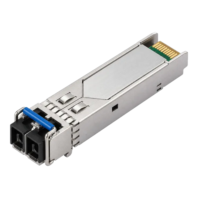
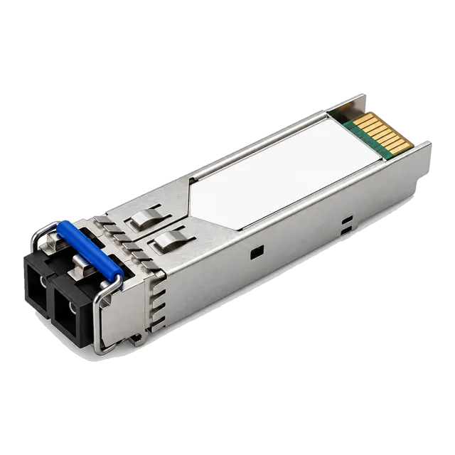
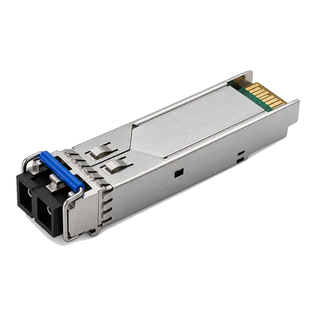
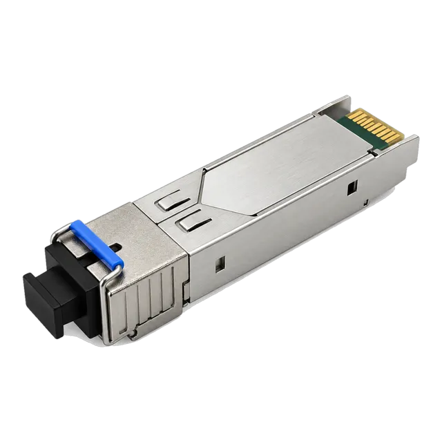
An SFP connector encompasses both the outer physical optical or copper interface, such as LC, SC, or RJ45, and the standardised 20-pin SFF-8431 host electrical edge card connecting transceiver hardware to network platforms.
01What is an SFP connector in modern optical networking?
An SFP connector refers to either the optical and copper interface presented on the front panel of a Small Form-factor Pluggable transceiver or the internal 20-pin electrical edge connector defined by the Small Form Factor Committee. When engineers specify an sfp connector, they must distinguish between the media-facing socket—such as a duplex LC receptacle, a simplex SC port, or an RJ45 jack—and the host-board edge connection governed by SFF-8431 and SFF-8074i. The transceiver module acts as an electro-optical bridge, converting differential current-mode logic signals on the host PCB into calibrated light pulses over glass fibres or balanced electrical signals over twisted-pair copper.
Understanding this physical distinction prevents costly mismatches during data centre and enterprise rollouts. Deploying an optical module such as the 100% Compatible 1.25G SFP Module SM 1310nm 20km Duplex LC requires matching both the internal cage footprint on the host switch and the external fibre patch cable terminating at the optical faceplate. A detailed breakdown of form-factor mechanics can be explored in our Small Form Factor Pluggable Module guide.
02SFP connector mechanical anatomy: front optical ports vs host edge cards
The mechanical architecture of an SFP transceiver separates cleanly into two discrete physical interfaces: the media interface unit and the host electrical interface. On the media side, precision ceramic split sleeves align mating ferrules to ensure that light couples between the internal Transmitter Optical Sub-Assembly (TOSA), Receiver Optical Sub-Assembly (ROSA), and the patch cord with minimal insertion loss. On the equipment side, a 0.8 mm pitch gold-plated card edge slides into an SFP cage receptacle soldered directly to the host system board.
The module housing incorporates an integrated die-cast zinc shell that provides mechanical rigidity, EMI grounding fingers to suppress electromagnetic interference, and an extraction bail clasp. The host cage connector provides positive retention latching, ensuring that thermal expansion, cable strain, and chassis vibration do not interrupt electrical contact across the 20 circuit traces defined by the multi-source agreement (MSA).
03Common optical interfaces: duplex LC and simplex LC explained
The duplex LC interface serves as the primary sfp fiber connector across enterprise, metro, and campus optical links. Utilising a 1.25 mm zirconia ceramic ferrule, the LC connector halves the rack footprint of legacy 2.5 mm SC connectors while maintaining an axial pull strength compliant with TIA-568. In standard dual-fibre links, one LC barrel connects to the transmitter channel while the adjacent barrel handles the receiver channel. Single-mode variants, like the 1.25G SFP 1310nm SMF Dual-Fiber Optical Transceiver 10km, require precise physical contact (UPC) polishing to keep optical return loss above 50 dB.
Conversely, simplex LC connectors appear on bidirectional (BiDi) transceivers that utilise internal wavelength-division diplexers. By transmitting on 1310 nm and receiving on 1550 nm through an internal optical filter, a single simplex LC port carries full-duplex Gigabit or 10G traffic across one strand of single-mode fibre. Understanding these port mechanics is essential when selecting cable assemblies, as detailed in our Single Mode Fiber Cable and Optical Transceiver Guide.
04Simplex SC connectors on legacy and access optical modules
Simplex SC connectors remain prevalent in passive optical network (PON) systems, access aggregation nodes, and industrial media conversion hardware. Featuring a 2.5 mm push-pull coupling mechanism defined by IEC 61754-4, the SC connector provides high mechanical retention and resistance to accidental disengagement in unmanaged environments. Many bidirectional access modules, such as the 1.25G SFP BiDi Optical Module 20km 1310nm/1550nm SC, utilise SC receptacles to mate with installed telecom OSP (outside plant) cabling plants.
While SC connectors require twice the front-panel area of LC connections, their larger ceramic ferrule offers exceptional durability under repeated mating cycles. In telecommunications drop cabinets and harsh industrial installations, the audible latching mechanism provides field technicians with positive physical confirmation of mating without risking ferrule contamination from adjacent patch cords.
05Copper RJ45 SFP connector modules for twisted-pair Ethernet
Copper SFP transceivers replace optical ferrules with an integrated 8P8C RJ45 modular jack, enabling standard Category 5e, 6, and 6a patch cords to link into SFP cages. Internally, a copper transceiver contains an integrated Physical Layer (PHY) chip that performs serial-to-parallel encoding, pulse amplitude modulation, and baseline wander correction. The host treats the transceiver as an SFP module, while the front panel exposes a standard gigabit or multi-gigabit twisted-pair socket.
Due to the electrical demands of Category-cable signal equalisation, RJ45 modules draw significantly more power than optical transceivers. A standard 1000BASE-T module draws approximately 1.05 W, whereas a 10GBASE-T unit can dissipate up to 2.5 W to 3.0 W per port, necessitating careful thermal planning when loading high-density switch chassis. Engineers transitioning access tiers can explore copper configurations within our Copper RJ45 SFP product family.
06Modem SFP modules: bridging PON, DSL and cable infrastructure
A modem sfp module integrates a complete broadband network termination unit within the compact SFP form factor, effectively replacing external customer premises equipment. These transceivers house internal systems-on-chip (SoCs) running lightweight microcode that executes media access control (MAC) processing for GPON, XGS-PON, VDSL2, or DOCSIS architectures. Rather than connecting an external modem via Ethernet, an enterprise router or firewall receives the modem SFP directly into its WAN cage.
This consolidation eliminates external power bricks, lowers rack space requirements, and unifies hardware management under the host router operating system. However, engineers must verify that the host SFP port supports the module's thermal dissipation profile and provides sufficient current over the 3.3 V rail, as active PON or DSL processing draws between 1.5 W and 2.2 W under heavy framing loads.
07Electrical pinout analysis: the SFF-8431 20-pin host edge connector
The internal 20-pin electrical connection on the SFP card edge is defined by the SFF-8074i specification for 1G transceivers and updated under SFF-8431 for SFP+ and SFP28 rates. The interface balances high-speed differential signal pairs with comprehensive ground isolation and low-speed management channels to preserve signal integrity up to 28 Gbps.
| Pin Number | Standard Name | Signal Logic / Type | Primary Functional Role |
|---|---|---|---|
| 1, 17, 20 | VeeT | Module Transmitter Ground | Transmitter return path and shield isolation |
| 2 | Tx_Fault | Open Collector Output (LVTTL) | Indicates laser degradation or laser safety shutdown |
| 3 | Tx_Disable | LVTTL Input (Pull-up inside) | Host command to disable laser output power |
| 4 | SDA | I2C Bidirectional Data Line | Serial clock/data interface for A0h/A2h memory map |
| 5 | SCL | I2C Clock Line | Serial bus synchronization line (nominal 100 kHz) |
| 6 | MOD_ABS | LVTTL Output (Grounded in mod) | Host presence detection line grounded inside module |
| 7 | RS0 | LVTTL Input (Rate Select 0) | Receiver bandwidth select (legacy / dual-rate) |
| 8 | Rx_LOS | Open Collector Output (LVTTL) | Loss of signal warning below photodiode sensitivity |
| 9 | RS1 | LVTTL Input (Rate Select 1) | Transmitter bandwidth select (legacy / dual-rate) |
| 10, 11, 14 | VeeR | Module Receiver Ground | Receiver analog/digital circuit ground reference |
| 12 | RD- | CML Differential Output | Inverted high-speed receiver data to host |
| 13 | RD+ | CML Differential Output | Non-inverted high-speed receiver data to host |
| 15 | VccR | 3.3 V ± 5% Receiver Power | Dedicated filtered DC power for receiver subassembly |
| 16 | VccT | 3.3 V ± 5% Transmitter Power | Dedicated filtered DC power for laser driver circuitry |
| 18 | TD+ | CML Differential Input | Non-inverted high-speed transmitter data from host |
| 19 | TD- | CML Differential Input | Inverted high-speed transmitter data from host |
08I2C management and DDM pin interactions
Digital Diagnostics Monitoring (DDM), also known as Digital Optical Monitoring (DOM), communicates across Pins 4 (SDA) and 5 (SCL) over a 2-wire serial protocol compliant with SFF-8472. This management subsystem maps internal operational parameters into two separate 256-byte EEPROM memory spaces. Memory table A0h holds static identification data including vendor nomenclature, serial numbers, wavelength, optical fibre type, and host compliance codes. Memory table A2h provides real-time digital readouts of internal operating conditions.
Through table A2h, network operating systems track transceiver internal temperature, DC operating voltage, laser bias current, transmitted optical power (Tx Power in dBm), and received optical power (Rx Power in dBm). Host firmware constantly polls these registers against factory-calibrated alarm and warning thresholds. When optical link degradation occurs—such as a dirty ferrule driving received power below safe operational limits—the transceiver updates register flags that trigger SNMP traps across the management plane. For advanced coding structures, see our guide on transceiver coding, EEPROM, and host support.
09Form-factor evolution: comparing SFP, SFP+, SFP28 and QSFP connectors
The mechanical footprint established by the original 1 Gbps SFP specification has evolved to support multi-gigabit data rates while maintaining backward physical cage dimensions where possible. The 10G SFP+ form factor retains the identical external dimensions and 20-pin card-edge layout of legacy 1G SFP, but upgrades the internal trace impedance, crosstalk mitigation, and contact metallisation to handle 10.3125 Gbps serial channels under SFF-8431.
SFP28 pushes this exact same mechanical geometry to 25.78125 Gbps per channel under IEEE 802.3by, demanding tighter signal integrity margins and enhanced thermal dissipation paths. In contrast, Quad Small Form-factor Pluggable (QSFP+/QSFP28) modules broaden the physical cage to support four independent electrical and optical channels in parallel, utilising a 38-pin edge connector. Engineers evaluating high-capacity inter-rack connections can compare these options in our 25G SFP28 transceiver series and 100G QSFP28 collection.
10Optical link budget and connector insertion loss calculation
Calculating total channel insertion loss is mandatory before deploying any optical transceiver assembly, as connector interfaces often account for more attenuation than the fibre cable itself. Standard single-mode fibre (ITU-T G.652.D) exhibits an attenuation coefficient of roughly 0.35 dB/km at 1310 nm and 0.22 dB/km at 1550 nm. In accordance with TIA-568 standards, each mated connector pair introduces a nominal insertion loss of 0.75 dB (though factory-grade low-loss LC connections typically achieve 0.20 dB to 0.30 dB).
To calculate link viability, apply the classic optical budget formula:
Optical Power Margin (dB) = Transceiver Link Budget (dB) - Channel Insertion Loss (dB)
Consider an operational example using the SFP-2.5G-LX20-SM1310 2.5G Single-Mode 1310nm 20km Duplex transceiver operating across an 18 km single-mode link with two patch panels (four mated connector pairs total):
- Determine Available Link Budget: Minimum Transmit Power (-9.0 dBm) minus Maximum Receiver Sensitivity (-20.0 dBm) yields an available optical budget of 11.0 dB.
- Calculate Fibre Cable Attenuation: 18 km × 0.35 dB/km = 6.3 dB.
- Calculate Connector Interface Loss: 4 mated connector pairs × 0.30 dB/pair = 1.2 dB.
- Calculate Fusion Splice Loss: Assume 2 field maintenance splices at 0.10 dB/splice = 0.2 dB.
- Sum Total Channel Attenuation: 6.3 dB + 1.2 dB + 0.2 dB = 7.7 dB.
- Calculate Net Power Margin: 11.0 dB - 7.7 dB = 3.3 dB.
Because the resulting net margin exceeds the recommended engineering safety buffer of 3.0 dB, the link will operate reliably over temperature and component ageing without bit errors.
11Ferrule polishing types: PC, UPC and APC connector differences
The geometric profile of the optical ferrule endface determines how much optical energy reflects back into the transmitter laser, an operational metric known as Optical Return Loss (ORL). Physical Contact (PC) ferrules present a slightly curved polish that brings fibre cores into direct contact, yielding an ORL of approximately -35 dB to -40 dB. Ultra Physical Contact (UPC) connectors use extended machine polishing to achieve a finer surface finish, improving return loss to -50 dB or better. UPC connectors feature a distinctive blue housing and represent the standard interface for digital Ethernet SFP transceivers.
Angled Physical Contact (APC) connectors, identified by their green plastic bodies, feature an 8-degree bevel ground across the ferrule face. This angle deflects reflected light out of the fibre core and into the surrounding cladding, yielding an industry-leading return loss of -65 dB or better. APC connectors are mandatory in broadband RF video networks, high-power Dense Wavelength Division Multiplexing (DWDM), and FTTH GPON architectures where back-reflections disrupt transmitter stability or cause optical crosstalk.
12Transceiver interface selection matrix
Selecting the optimal SFP interface requires balancing medium constraints, bandwidth demands, reach, and port density. The following comparison matrix details standard mechanical and electrical parameters across mainstream connector variants.
| Connector Variant | Physical Media | Standard Ferrules / Contacts | Optical Return Loss (dB) | Typical Insertion Loss (dB) | Max Channel Reach |
|---|---|---|---|---|---|
| Duplex LC (UPC) | SMF (G.652/G.657) | Dual 1.25 mm ceramic | ≥ 50 dB | 0.20 – 0.35 dB | Up to 120 km |
| Duplex LC (PC) | MMF (standard multimode fibre) | Dual 1.25 mm ceramic | ≥ 30 dB | 0.20 – 0.35 dB | Up to 400 m |
| Simplex LC (UPC) | Single-strand SMF | Single 1.25 mm ceramic | ≥ 50 dB | 0.25 – 0.40 dB | Up to 80 km |
| Simplex SC (APC) | Single-strand SMF | Single 2.5 mm angled ceramic | ≥ 65 dB | 0.25 – 0.40 dB | Up to 40 km |
| RJ45 Modular | Cat5e / Cat6 / Cat6a | 8 Gold-plated pins | N/A (VSWR) | 1.5 – 2.5 dB (atten.) | 100 m (1G) / 30 m (10G) |
| Card Edge (Host) | FR4 / Megtron PCB | 20 Microstrip gold fingers | N/A (S-parameters) | 0.10 – 0.20 dB | Host trace dependent |
13Inspection, cleaning and maintenance of SFP optical ports
Contamination on the optical ferrule endface remains the single largest cause of link degradation, intermittent packet loss, and field component failure. Dust particles measuring as small as 1 to 2 micrometres can completely obscure a 9-micrometre single-mode fibre core, inducing severe attenuation or permanently pitting the glass during connection mating. Technicians must inspect every optical connector using an optical microscope or digital probe prior to insertion.
Maintain optical connections using the following five-step protocol:
- Inspect First: Use an automated fiber inspection microscope to check both the transceiver optical port and the mating patch cord ferrule for particulate contamination, oil films, or scratches.
- Dry Clean: Insert an appropriately sized mechanical click-cleaner (1.25 mm for LC, 2.5 mm for SC) directly into the transceiver bore or against the ferrule, rotating the cleaning strand under controlled spring pressure.
- Re-inspect: Verify that the endface meets IEC 61300-3-35 cleanliness criteria across core, cladding, adhesive, and contact zones.
- Wet-to-Dry Clean if Required: If stubborn oil deposits or residue remain, apply an optical-grade solvent pen to a lint-free wipe, swipe the connector across the wetted zone into the dry zone, and re-inspect.
- Install Dust Caps Immediately: Never leave an unmated SFP transceiver or patch cord open to ambient air; replace factory dust covers immediately upon disconnection.
14How to specify SFP connectors in procurement RFQs
To eliminate ambiguity when generating Requests for Quotation (RFQs) for optical transceivers and patch assemblies, procurement teams must provide unambiguous mechanical and electrical specifications. A complete procurement checklist prevents supply chain mismatches between switch ports, transceivers, and plant cabling.
- Connector Form and Polish: Clearly state connector footprint and polish geometry (e.g., Duplex LC/UPC, Simplex LC/UPC, or Simplex SC/APC).
- Host Interface Standard: Specify compliance criteria (e.g., SFF-8431, SFF-8472 with real-time DDM/DOM operational telemetry).
- Optical Media Specification: State exact core and cladding diameters (e.g., 9/125 µm single-mode compliant with ITU-T G.652.D or 50/125 µm multimode OM4).
- Operating Spectral Window: Cite nominal centre wavelength and transmission technology (e.g., 1310 nm Fabry-Pérot/DFB laser or 850 nm VCSEL).
- Thermal Rating and Power Budgets: Detail required operating temperature range (Commercial 0°C to 70°C or Industrial -40°C to +85°C) and maximum power consumption limits.
- Host Platform Compatibility: Include target switch hardware platform part numbers to ensure EEPROM tables A0h and A2h are appropriately coded prior to dispatch.
For custom production, system testing, or technical inquiries regarding transceiver connectors and switch coding, contact our engineering team directly at our contact page or email inquiry@optical-module-factory.com.
15Frequently asked questions
What is the most common connector used on an SFP module?
The duplex LC connector is the most common optical interface found on SFP and SFP+ modules. It uses two compact 1.25 mm ceramic ferrules for separate transmit and receive channels, providing twice the port density of older 2.5 mm SC connectors.
Can you plug a copper Ethernet cable directly into an SFP port?
No, a standard RJ45 copper Ethernet cable cannot be plugged directly into an empty SFP cage. You must first insert a copper 1000BASE-T or 10GBASE-T SFP transceiver module, which provides the necessary RJ45 connector and internal PHY conversion circuitry.
What is the difference between an LC and SC SFP connector?
LC connectors utilise a 1.25 mm ceramic ferrule and a latching tab, making them compact and ideal for high-density duplex transceivers. SC connectors use a larger 2.5 mm ferrule with a push-pull mechanism, commonly used in legacy systems and single-fibre BiDi access links.
Can you connect an APC green connector to a standard blue SFP module?
No, you should never insert an angled APC (green) connector into an SFP transceiver designed for UPC (blue) connections. The 8-degree angle mismatch causes severe insertion loss, high reflection, and can permanently crush the optical core or internal transceiver ferrule.
What is a modem SFP module used for?
A modem SFP module integrates broadband termination hardware—such as GPON, XGS-PON, or VDSL2—directly into an SFP form factor. It plugs into a router or firewall SFP port, eliminating the need for an external standalone modem or ONT hardware.
How does an SFP connector handle DDM monitoring?
DDM data is communicated via Pins 4 (SDA) and 5 (SCL) of the module's 20-pin host edge connector using an I2C serial protocol. The host switch reads real-time metrics including optical Tx/Rx power, laser bias current, voltage, and temperature from memory address A2h.
Technical review note: confirm model-specific specifications with the product datasheet and the intended host documentation. Product images and application photographs are illustrative.
Discuss this with our team