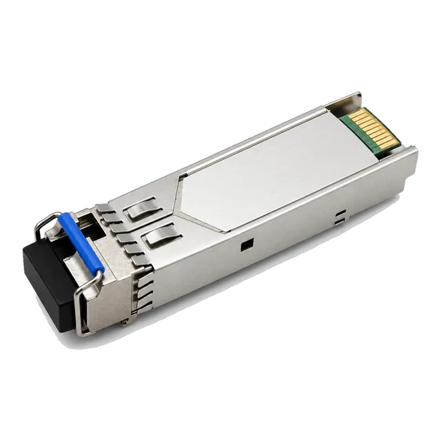
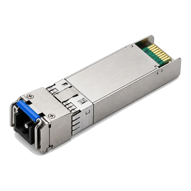
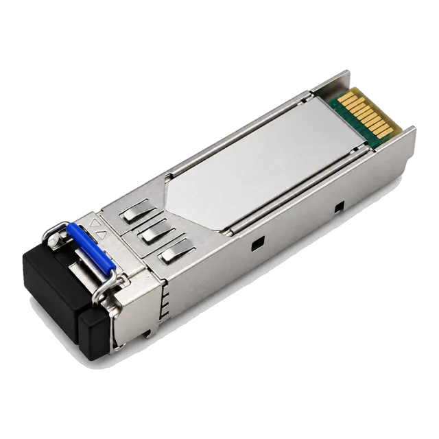
A bidirectional SFP halves outside plant fibre consumption by multiplexing complementary transmit and receive wavelengths through an internal WDM diplexer over a single strand, requiring strictly matched complementary transceiver pairs across every optical link.
01What is a bidirectional SFP and how does single-strand transmission work?
A bidirectional SFP is an optical transceiver that transmits and receives optical signals over a single strand of optical fibre by using two distinct optical wavelengths. Traditional duplex optical modules allocate one physical core to transmission (Tx) and a separate dedicated core to reception (Rx). In contrast, a bidirectional sfp module integrates an internal wavelength division multiplexing (WDM) diplexer filter that isolates outgoing light from incoming light within the same physical optical port.
This single-fibre architecture immediately doubles the capacity of existing dark fibre assets without laying new outside plant cabling. By deploying a complementary optical pair, a network operator converts one dual-fibre conduit into two independent full-duplex communication links. The fundamental operating rule of any bidirectional sfp deployment dictates that Module A's transmit wavelength must strictly match Module B's receive wavelength, and Module B's transmit wavelength must correspond exactly to Module A's receive wavelength. Standardised under specifications including IEEE 802.3ah (1000BASE-BX10) and IEEE 802.3ae, single-strand transceivers deliver identical line-rate throughput and bit error ratio (BER) performance to legacy dual-fibre optics.
02How the internal WDM diplexer eliminates optical crosstalk
The internal optical diplexer prevents high-power local transmitter emissions from blinding the local sensitive photodetector through optical isolation. Inside a typical bidi sfp transceiver, an internal laser diode emits light at wavelength $\lambda_1$, which travels through an angled thin-film filter (TFF) directly into the single-mode optical fibre stub. Simultaneously, incoming light at wavelength $\lambda_2$ arriving from the far-end terminal hits the identical dielectric filter, which reflects $\lambda_2$ at a 45-degree angle toward the internal photodiode detector while rejecting any backscattered energy from $\lambda_1$.
Achieving stable operation requires the diplexer to provide an optical isolation figure of at least 30 dB, and frequently exceeding 40 dB in long-reach optical designs. Without adequate isolation, local optical back-reflections caused by dirty optical connectors or Rayleigh backscattering along the single-mode silica core introduce optical return loss (ORL) penalties that corrupt incoming bit streams. Telecommunication standards defined in ITU-T G.694.2 and Telcordia GR-468-CORE specify strict environmental and isolation benchmarks to guarantee that local laser leakage remains at least 30 dB below the minimum receiver sensitivity threshold across all operating temperatures.
03Standard optical wavelength pairings across speed grades
Standard single-strand deployments rely on predetermined optical wavelength combinations engineered around physical fibre attenuation windows and laser physics. At Gigabit Ethernet line rates, systems standardise on 1310 nm and 1490 nm or 1310 nm and 1550 nm pairs over standard ITU-T G.652 single-mode fibre. As link speeds step up to 10G, 25G, and 100G, material dispersion constraints necessitate narrower spectral widths, shifting channel plans to specialized 1270 nm and 1330 nm allocations.
The table below outlines standard industrial and telecommunication wavelength combinations deployed across single-strand networks:
| Data Rate (Gb/s) | Standard Designation | Upstream Tx / Rx (nm) | Downstream Tx / Rx (nm) | Typical Distance (km) | Laser & Detector Type |
|---|---|---|---|---|---|
| 1.25 | 1000BASE-BX10 | 1310 / 1490 | 1490 / 1310 | 10 – 20 | FP / PIN |
| 1.25 | 1000BASE-BX40 | 1310 / 1550 | 1550 / 1310 | 40 | DFB / PIN |
| 2.5 | 2.5GBASE-BX | 1310 / 1490 | 1490 / 1310 | 20 – 40 | DFB / PIN |
| 10 | 10GBASE-BX10 | 1270 / 1330 | 1330 / 1270 | 10 – 20 | DFB / PIN |
| 10 | 10GBASE-BX (40–60 km) | 1270 / 1330 | 1330 / 1270 | 40 – 60 | DFB / APD |
| 10 | 10GBASE-BX80 | 1490 / 1550 | 1550 / 1490 | 80 | EML / APD |
| 25 | 25GBASE-BX10 | 1270 / 1330 | 1330 / 1270 | 10 – 20 | DFB / PIN |
| 100 | 100GBASE-BX10 | 1271 / 1331 | 1331 / 1271 | 10 | EML / PIN |
For network engineers ordering inventory, consulting a practical BiDi pairing checklist prevents mismatched optical pairs before site dispatch.
04Why 1310 nm and 1490 nm or 1550 nm pairings dominate 1G links
Gigabit single-strand systems leverage 1310 nm, 1490 nm, and 1550 nm because these wavelengths align with low-cost Fabry-Pérot (FP) and Distributed Feedback (DFB) laser fabrication processes. Standard ITU-T G.652.D single-mode fibre exhibits its zero-dispersion wavelength near 1312 nm, making 1310 nm optimal for uncooled transmitters over distances up to 20 km. At 1.25 Gb/s, chromatic dispersion tolerances are broad enough that inexpensive broad-spectrum lasers operate reliably without severe inter-symbol interference.
For spans extending past 20 km up to 40 km, transceivers such as the 1.25G BiDi Single-Fiber SFP Transceiver 1310nm/1550nm 20km pair a 1310 nm transmitter with a 1550 nm channel. Moving to 1550 nm reduces fibre attenuation from roughly 0.35 dB/km down to 0.20 dB/km, balancing optical attenuation against the link budget. For enterprise routing and switches requiring legacy interfaces, engineers can reference the dedicated 1.25G SFP category for both LC and SC simplex termination formats.
05Why 10G and 25G bidirectional SFP optics standardise on 1270 nm and 1330 nm
Higher line rates shift to 1270 nm and 1330 nm pairings because chromatic dispersion at 10 Gb/s and 25 Gb/s penalises transmission in the 1550 nm C-band over standard G.652 single-mode fibre. In optical physics, chromatic dispersion increases quadratically with modulation speed. At 10 Gb/s, an unamplified 1550 nm signal experiences severe pulse broadening after roughly 40 km, whereas near the 1310 nm zero-dispersion window, chromatic dispersion drops below 3.5 ps/(nm·km).
The 60 nm spectral spacing between 1270 nm and 1330 nm balances laser isolation against manufacturing yields for uncooled DFB lasers across varying ambient operating envelopes. Transceivers such as the 10G SFP+ BiDi BX100 100km 1490/1550nm Simplex LC Transceiver push past these boundaries to reach 100 km, but they require high-specification Electro-absorption Modulated Lasers (EML) and Avalanche Photodiode (APD) receivers to overcome dispersion and sensitivity constraints. For full campus and metropolitan aggregation spans, consult our 10G SFP+ product family.
06Calculating an optical link budget for a single-strand BiDi span
Calculating a link budget for a bidirectional sfp span requires evaluating attenuation at both complementary wavelengths because single-mode optical fibre attenuates light unevenly across different spectral regions. In standard ITU-T G.652 fibre, attenuation averages 0.35 dB/km at 1310 nm, 0.25 dB/km at 1490 nm, and 0.20 dB/km at 1550 nm. The link's operating margin must be verified against the weaker optical channel, which is almost invariably the shorter wavelength running over higher attenuation.
The optical power budget equation is defined as:
$$P_{\text{budget}} = P_{\text{Tx, min}} - P_{\text{Rx, min}}$$
The total channel insertion loss is calculated using:
$$\alpha_{\text{link}} = (L \times \alpha_{\text{fibre}}) + (N_{\text{c}} \times \alpha_{\text{c}}) + (N_{\text{s}} \times \alpha_{\text{s}}) + M_{\text{safety}}$$
Consider a 35 km outside plant link operating with a 1310 nm / 1490 nm 1.25 Gb/s transceiver pair featuring $P_{\text{Tx, min}} = -2.0\text{ dBm}$ and $P_{\text{Rx, min}} = -23.0\text{ dBm}$, yielding an available optical power budget of $21.0\text{ dB}$. The plant incorporates 4 patch panel mating sleeves ($0.5\text{ dB}$ each), 6 fusion splices ($0.1\text{ dB}$ each), and a mandatory $3.0\text{ dB}$ engineering safety margin:
- Loss at 1310 nm: $(35\text{ km} \times 0.35\text{ dB/km}) + (4 \times 0.5\text{ dB}) + (6 \times 0.1\text{ dB}) + 3.0\text{ dB} = 12.25 + 2.0 + 0.6 + 3.0 = 17.85\text{ dB}$
- Loss at 1490 nm: $(35\text{ km} \times 0.25\text{ dB/km}) + (4 \times 0.5\text{ dB}) + (6 \times 0.1\text{ dB}) + 3.0\text{ dB} = 8.75 + 2.0 + 0.6 + 3.0 = 14.35\text{ dB}$
The limiting path is the 1310 nm upstream link, which requires $17.85\text{ dB}$. Since the transceiver provides an available budget of $21.0\text{ dB}$, the remaining operational power margin is $3.15\text{ dB}$, confirming the link will function reliably without optical amplification. For deeper analysis, explore our guide on optical link budget calculations or verify figures through the online link budget calculator.
07Simplex LC versus SC connector interfaces in field deployments
Simplex LC and simplex SC connectors serve distinct operational roles based on mechanical density, patch panel architecture, and legacy infrastructure constraints. The LC connector utilizes a 1.25 mm ceramic ferrule and a positive push-pull latching mechanism compliant with IEC 61754-20, making it the universal choice for high-density modern switch platforms, enterprise SFP cages, and dense telecommunication distribution frames.
The SC connector utilizes a 2.5 mm ceramic ferrule specified in IEC 61754-4, delivering superior mechanical durability against repeated field matings and vibration in rugged outside-plant enclosures. Telecommunications service providers frequently deploy SC-terminated bidi sfp units in Gigabit Passive Optical Network (GPON) customer premises equipment, media converter cabinets, and remote terminal closures. When mating connectors, verify ferrule end-face geometries; physical contact (UPC) and angled physical contact (APC) connectors cannot be mated directly without catastrophic optical return loss and physical surface damage.
08Diagnostic monitoring via SFF-8472 digital optical monitoring (DDM)
Digital Diagnostic Monitoring (DDM), governed by the industry-standard SFF-8472 specification, provides real-time telemetry on the critical physical layer parameters of the optical module. A microcontroller inside the bidirectional sfp module monitors five essential operational metrics via an internal $I^2C$ serial bus accessible at two-wire address 1010001X (A2h): internal temperature, operating supply voltage, laser bias current, transmitter output power, and received optical power.
For single-strand bidirectional optics, real-time monitoring of receiver optical power ($P_{\text{Rx}}$) and laser bias current ($I_{\text{bias}}$) provides rapid fault isolation. An escalating laser bias current indicates aging semiconductor laser junctions attempting to maintain target optical output power against thermal stress. Conversely, a sudden drop in received optical power without a corresponding shift in local transmitter metrics isolates the fault to the external outside plant fibre, pinpointing microbends, dirty patch interfaces, or physical cable severance. For diagnostic implementation details, refer to our technical breakdown of what DDM can tell you about an optical link.
09Deploying 2.5G and 100G single-strand optics in aggregation networks
Deploying single-strand optics at multi-gigabit data rates enables high-density backhaul without the capital expenditure of leasing or installing additional single-mode cores. In wireless broadband infrastructure and optical access aggregation, 2.5 Gb/s links provide high utility. Deployments like the 2.5G BiDi SFP-2.5G-BX120 Single-Fiber 1490/1550nm 120km Transceiver bridge long carrier spans across rural regional loops.
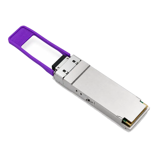
At the 100G aggregation layer, modern QSFP28 architecture utilizes four-level pulse amplitude modulation (PAM4) and single-lambda optics to accomplish bidirectional traffic over one strand. Standardised under 100GBASE-BX10 specifications, optics such as the 100GBASE-BX10 QSFP28 BiDi 1271/1331nm 10km Simplex LC SMF Module incorporate integrated host Reed-Solomon Forward Error Correction (RS-FEC) to maintain a post-FEC bit error ratio below $10^{-12}$. For architecture planning across core routing layers, see our detailed overview of small form factor pluggable modules.
10How transceiver coding and EEPROM configurations prevent host rejection
Host network switches enforce strict vendor validation by reading internal EEPROM memory addresses 00 to 127 at two-wire address 1010000X (A0h) compliant with SFF-8024 and SFF-8472. When an engineer inserts a bidirectional sfp, the host operating system queries bytes 20 to 35 for vendor identification strings, bytes 40 to 55 for vendor part numbers, and bytes 63 to 64 for checksum calculations. If these values fail cryptographic signature checks or vendor-specific serialisation lookups, the port disables the transmitter and logs an 'unsupported transceiver' fault.
Achieving reliable compatibility across diverse switch estates requires accurate EEPROM programming tailored to each target platform. The hardware architecture of high-grade third-party transceivers incorporates programmable microcontrollers that mirror vendor identification tables, hardware revisions, and diagnostic register tables without altering standard physical-layer electrical compliance. More details on EEPROM maps are available in our technical manual on transceiver coding and host support.
11Troubleshooting common bidirectional link failures in the field
Field failures on single-strand optical circuits almost universally stem from paired-wavelength mismatches, excessive insertion loss, or optical return loss caused by uncleaned end-faces. When commissioning a new circuit, follow this troubleshooting sequence to isolate faults systematically:
- Verify Transceiver Wavelength Pairing: Inspect the physical labels on both optical modules. Ensure one side is Tx 1310 nm / Rx 1490 nm (or Tx 1270 nm / Rx 1330 nm) and the opposite end is Tx 1490 nm / Rx 1310 nm (or Tx 1330 nm / Rx 1270 nm). Installing two identical units (e.g. Tx 1310 nm on both ends) will prevent link establishment.
- Inspect Connector Types and Polish: Confirm that connectors match ferrule geometry. Mating an angled polish (APC, green housing) to an ultra-physical polish (UPC, blue housing) introduces an insertion loss exceeding 4 dB and damages the glass cores.
- Read DDM Rx Power Levels: Query the switch command line interface to view optical diagnostic metrics. If received optical power ($P_{\text{Rx}}$) reads below the specified receiver sensitivity, clean all optical connector end-faces using an optical dry-cleaning cassette and inspect patch cables for severe bend radii exceeding 30 mm.
- Evaluate Optical Saturation on Short Links: If deploying high-power long-reach optics (e.g., 40 km or 80 km rated modules) across test benches or short spans under 10 km, verify that $P_{\text{Rx}}$ does not exceed the optical saturation threshold. If the receiver is overloaded, insert fixed optical attenuators (5 dB or 10 dB) to protect the photodetector from damage.
- Validate Host Port Speed and Auto-Negotiation: Ensure switch ports on both terminals are manually locked to identical speed and duplex settings. Many 10G and 25G host switches fail to link if one end attempts speed auto-negotiation while the other remains fixed.
12Step-by-step RFQ checklist for bidirectional optics procurement
Procurement teams must provide complete technical parameters when issuing a Request for Quote (RFQ) for single-strand optics to avoid operational delays and delivery of incompatible components. Optical transceivers require precise matching across wavelength, power budget, host operating system coding, and environmental thresholds.
Ensure your RFQ contains the following technical specifications:
- Line Rate and Standard: State the exact target protocol (e.g., 1.25 Gb/s 1000BASE-BX, 10.3125 Gb/s 10GBASE-BX, 25.78125 Gb/s 25GBASE-BX).
- Wavelength Complementarity: Order optics in matched pairs, specifying explicit Upstream (Tx $\lambda_1$ / Rx $\lambda_2$) and Downstream (Tx $\lambda_2$ / Rx $\lambda_1$) quantities in equal ratios.
- Link Distance and Optical Power Budget: Specify required minimum power budget (in dB) and expected physical distance (e.g., 10 km, 20 km, 40 km, 80 km) over standard G.652.D single-mode fibre.
- Physical Optical Interface: Specify whether simplex LC or simplex SC termination is required, along with end-face polish (UPC blue or APC green).
- Operating Temperature Range: Designate Commercial Temperature ($0^\circ\text{C}$ to $+70^\circ\text{C}$), Extended Temperature ($-20^\circ\text{C}$ to $+85^\circ\text{C}$), or Industrial Temperature ($-40^\circ\text{C}$ to $+85^\circ\text{C}$) based on cabinet environmental controls.
- Host Platform Target Coding: List the exact switch brand, chassis model, and operating system software release running on each end of the circuit to ensure EEPROM pre-coding.
- Diagnostic Telemetry Compliance: Require full support for SFF-8472 Digital Diagnostic Monitoring (DDM/DOM) with factory calibration.
13Frequently asked questions
Can I connect two identical BiDi SFP modules together?
No, you cannot connect two identical bidirectional SFP modules together. A BiDi link requires a complementary pair where one module transmits at wavelength A and receives at wavelength B, while the opposite module transmits at wavelength B and receives at wavelength A. Connecting two identical modules results in both lasers transmitting on the same wavelength with zero reception.
What is the difference between a BiDi SFP and a standard duplex SFP?
A standard duplex SFP uses two separate fibre strands—one dedicated to transmit and one to receive—usually operating at the same nominal wavelength. A bidirectional SFP uses a single fibre strand for both transmission and reception by employing an internal optical diplexer and two distinct wavelengths, cutting physical fibre requirements in half.
Does a bidirectional SFP add latency compared to duplex modules?
No, a bidirectional SFP does not add measurable latency compared to a duplex module. Light at different optical wavelengths travels simultaneously through single-mode silica fibre at approximately two-thirds the speed of light in a vacuum. The passive optical filtering performed by the internal WDM diplexer introduces negligible sub-picosecond propagation delay.
Can a BiDi SFP operate over multimode fiber?
Standard bidirectional SFP transceivers are engineered strictly for single-mode optical fibre (OS2) using 1310 nm, 1490 nm, or 1550 nm wavelengths. Standard single-mode BiDi optics experience extreme modal dispersion and high attenuation if connected to multimode fibre (OM4), drastically degrading link distance and inducing bit errors.
How do I know which BiDi module is the upstream or downstream unit?
Manufacturers label bidirectional modules with their explicit transmit and receive wavelengths, often designated as 'U' (Upstream) and 'D' (Downstream), or as BX-U and BX-D. Alternatively, modules are color-coded on the optical bail latch. Always match a Tx1310/Rx1490 module with a Tx1490/Rx1310 module across the link.
Technical review note: confirm model-specific specifications with the product datasheet and the intended host documentation. Product images and application photographs are illustrative.
Discuss this with our team