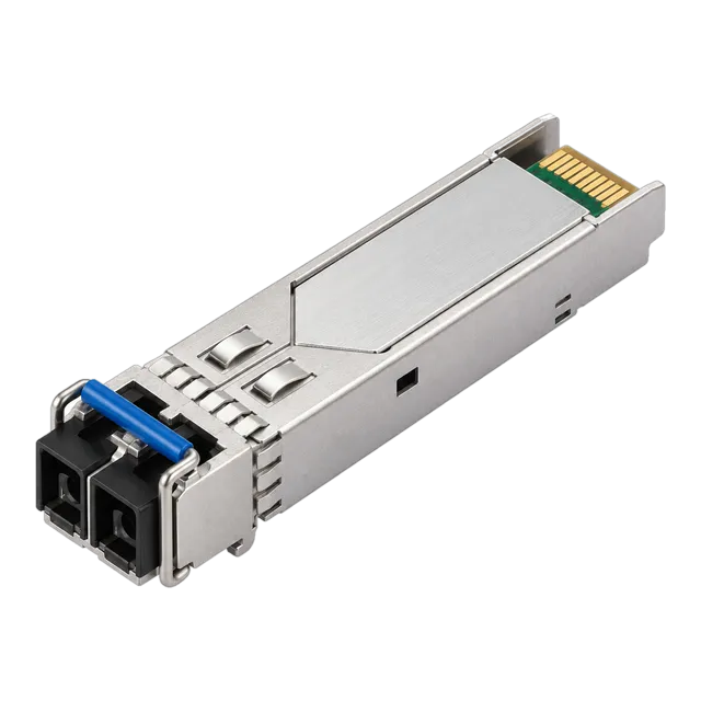
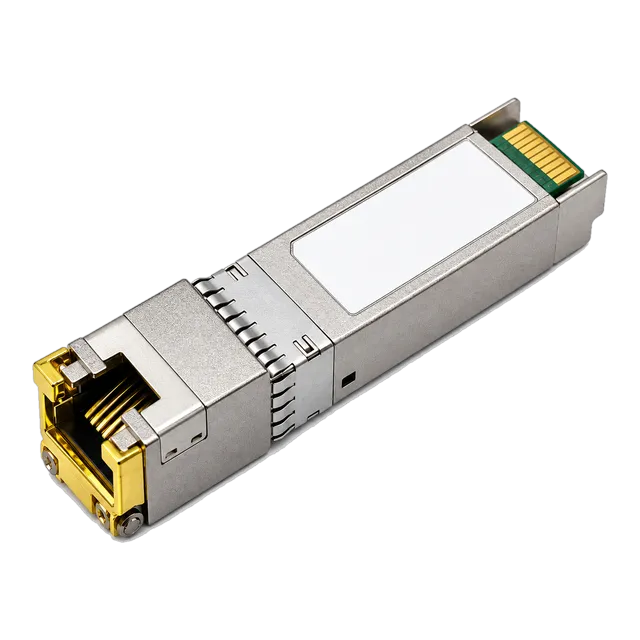
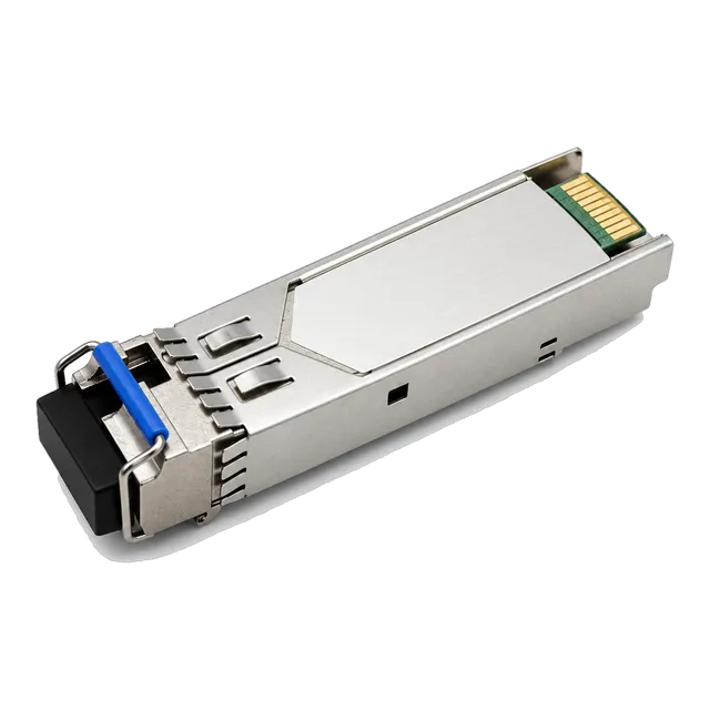
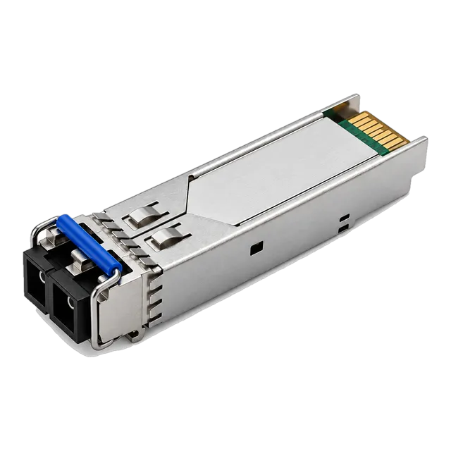
A small form factor pluggable module bridges host electronics to physical media using open MSA standards, where correct optical power budgeting, physical connector matching, and vendor-specific EEPROM memory-map coding guarantee line-rate network interoperability.
01What is a small form factor pluggable module?
A small form factor pluggable module is a compact, hot-swappable hardware transceiver that interfaces a host network device—such as a switch, router, or network interface card (NIC)—to optical fibre or copper networking cables. Operating as a physical-layer protocol transducer, the small form factor pluggable module converts differential electrical current signals from host printed circuit boards into calibrated serial optical pulses, or conversely into balanced electrical pulses for twisted-pair copper media.
Standardised under open industry agreements rather than single-vendor proprietary designs, these transceivers permit network operators to mix transmission media, optical reach, and channel wavelengths across a uniform physical host faceplate. Instead of fixing network line interfaces at switch fabrication, modular bays accept interchangeable hardware tailored to specific optical link distances from 100 metres to beyond 120 kilometres.
02What does SFP stand for in networking?
In networking, SFP stands for Small Form-factor Pluggable, identifying a modular line-card interface standardised by multi-source agreements. The term originated in 2001 through the SFF Committee (now integrated into the SNIA SFF Technology Affiliate) to establish an interface half the physical width of legacy Gigabit Interface Converter (GBIC) housings.
The standard SFP footprint measures approximately 8.5 mm in height, 13.4 mm in width, and 56.5 mm in depth. By halving the horizontal rack space requirement of earlier interfaces, network hardware designers achieved 24 or 48 ports across a standard 1U 19-inch rack shelf. Today, defining an sfp transceiver module implies adherence to mechanical specifications defined in SFF-8431, electrical parameters established in SFF-8472, and standard 20-pin card-edge connector pinouts that deliver bidirectional serial data alongside two-wire I2C management signalling.
03How an SFP transceiver works inside the host port
An optical SFP transceiver functions by executing continuous bidirectional electrical-to-optical (E-O) and optical-to-electrical (O-E) conversion across dedicated internal sub-assemblies. The host equipment provides a regulated 3.3 V DC rail across pins 15 and 16, powering the internal transmitter optical sub-assembly (TOSA) and receiver optical sub-assembly (ROSA).
During transmission, host Serializer/Deserializer (SerDes) channels push high-speed differential current mode logic (CML) signals into the module across the TX+ and TX- edge pins. The internal laser driver converts these electrical transitions into modulated drive current, firing a semiconductor laser diode—typically an 850 nm Vertical-Cavity Surface-Emitting Laser (VCSEL) for short-reach multimode links, or a 1310 nm Fabry-Pérot (FP) / Distributed Feedback (DFB) laser for single-mode runs. In the receive direction, the ROSA houses an InGaAs PIN photodiode or an Avalanche Photodiode (APD) combined with a Transimpedance Amplifier (TIA), which recovers the attenuated optical light pulses, transforms them into electrical current, and outputs regenerated differential CML signals to the host across RX+ and RX- pins.
04SFP port architecture and host hardware interfaces
An SFP port is a cage receptacle mounted directly onto a host network switch or router mainboard, containing a 20-position gold-plated card-edge connector. The mechanical cage grounds the inserted metal transceiver housing to the chassis, mitigating electromagnetic interference (EMI) and serving as a thermal conduction pathway.
Beyond standard high-speed differential data pairs, the 20-pin physical interface defined in SFF-8431 provides crucial low-speed control and status circuits: pin 2 (TX_Fault) signals laser operational errors; pin 3 (TX_Disable) allows host firmware to extinguish optical output; pin 6 (MOD_ABS) indicates physical module presence; and pin 8 (RX_LOS) detects the loss of incoming optical carrier signal. Pins 4 and 5 form the serial I2C management bus (SCL and SDA), which hosts interrogate to verify EEPROM identification tables and extract real-time operational diagnostics.
05Evolution of form factors: SFP, SFP+, SFP28, QSFP, and QSFP28
Network line rates have accelerated from legacy 1.25 Gbps Gigabit links to dense 100 Gbps architectures, prompting evolutionary form-factor advancements while maintaining backward-compatible form factors where feasible. Higher speeds demand improved high-frequency dielectric materials, tighter impedance controls, and advanced digital signal processing inside the transceiver envelope.
The standard SFP housing initially served Fast Ethernet and 1G Gigabit Ethernet (IEEE 802.3z). The mechanical outline was retained for 10G SFP+ (IEEE 802.3ae) and 25G SFP28 (IEEE 802.3by), which utilise single-lane electrical SerDes rates running at 10.3125 Gbps and 25.78125 Gbps respectively. In contrast, Quad Small Form-factor Pluggable architectures widen the envelope to integrate four parallel electrical lanes: 40G QSFP+ aggregates four 10 Gbps channels, while 100G QSFP28 bonds four 25 Gbps lanes. Modern enterprise and carrier networks systematically procure 1.25G SFP modules for edge access, transitioning to SFP28 and QSFP28 inside aggregation points and leaf-spine fabrics.
06Fibre optic SFP module types: multimode, single-mode, and BiDi
Fibre optic SFP modules are categorised by their internal laser wavelength, optical core compatibility, and connectorisation. Multimode transceivers (such as 1000BASE-SX) deploy 850 nm VCSEL lasers matched to 50/125 µm OM4 fibre cores, restricted by modal dispersion to links under 550 metres. Single-mode transceivers (such as 1000BASE-LX or 1000BASE-EX) utilise narrow-spectrum 1310 nm or 1550 nm DFB emitters paired with 9/125 µm ITU-T G.652.D fibre to traverse distances from 10 km to 80 km.
Bidirectional (BiDi modules) introduce single-strand operational economics by integrating internal diplexer prisms. Instead of requiring two parallel fibres for transmit and receive paths, a BiDi transceiver transmits at one wavelength (e.g., 1310 nm) and receives at another (e.g., 1550 nm) over a single simplex LC connection. When deploying a transceiver such as the 1.25G BiDi Single-Fiber SFP Transceiver, engineers must deploy complementary upstream (1310TX/1550RX) and downstream (1550TX/1310RX) endpoints to establish link sync.
07Copper RJ45 SFP transceivers: standards and thermal constraints
Copper SFP transceivers substitute optical transmitter sub-assemblies with an integrated physical layer (PHY) transceiver chip and pulse transformers terminated on an RJ45 modular jack. Modules compliant with IEEE 802.3ab (1000BASE-T) deliver full-duplex Gigabit connectivity across Category 5e or Category 6 unshielded twisted-pair (UTP) structured cabling up to the 100-metre channel limit.
Thermal dissipation represents the primary operational constraint when using copper SFP hardware. An optical SFP consumes between 0.6 W and 1.0 W, whereas a 1000BASE-T SFP Copper RJ45 module draws between 1.05 W and 1.3 W. Multi-gigabit 10GBASE-T SFP+ modules draw up to 2.5 W to 3.0 W per unit. In switches with dense horizontal transceiver arrays, deploying copper modules side-by-side can cause local cage temperatures to exceed the commercial 70°C ceiling, triggering PHY thermal throttling or port resets. Network architects should stagger copper modules across alternate switch cages and reserve copper transceivers for short patch connections.
08Key technical specifications: wavelengths, reach, and link budgets
Selecting an optical transceiver requires precise alignment between the physical link loss and the optical transceiver's guaranteed power budget. Operating parameters are bound by minimum transmit power, maximum transmit power, receiver sensitivity, and receiver saturation thresholds.
The table below details standard SFP operating parameters based on IEEE 802.3 and MSA specifications:
| Standard Designation | Media Type | Nominal Wavelength (nm) | Min Launch Power (dBm) | Receiver Sensitivity (dBm) | Receiver Overload (dBm) | Max Reach (km) |
|---|---|---|---|---|---|---|
| 1000BASE-SX | Multimode (OM4) | 850 | -9.5 | -17.0 | 0.0 | 0.55 |
| 1000BASE-LX | Single-Mode (G.652) | 1310 | -9.0 | -19.0 | -3.0 | 10.0 |
| 1000BASE-EX | Single-Mode (G.652) | 1310 | -3.0 | -22.0 | -3.0 | 40.0 |
| 1000BASE-ZX | Single-Mode (G.652) | 1550 | 0.0 | -22.0 | -3.0 | 80.0 |
| 1000BASE-EZX | Single-Mode (G.652) | 1550 | +5.0 | -30.0 | -9.0 | 120.0 |
| 2.5GBASE-LX | Single-Mode (G.652) | 1310 | -5.0 | -18.0 | -3.0 | 20.0 |
| 1000BASE-T | Copper (Cat5e/Cat6) | Electrical | N/A | N/A | N/A | 0.10 |
To avoid optical receiver damage on test benches or short spans, engineers must never connect long-reach optics (such as 80 km ZX or 120 km EZX models) without verifying that path attenuation exceeds the minimum span loss. If launch power surpasses the receiver overload figure, calibrated in-line optical attenuators must be inserted before line activation.
09Worked calculation: optical link loss budget for a 20 km span
A reliable optical link calculation ensures that total passive attenuation across installed fibre infrastructure remains below the available optical power budget, factoring in an engineering safety margin. Available optical power budget ($PB$) is defined by subtracting the receiver sensitivity ($P_{RX\_min}$) from the minimum transmitter launch power ($P_{TX\_min}$):
$$\text{Power Budget } (PB) = P_{TX\_min} - P_{RX\_min}$$
Consider an enterprise link deployment using the 2.5G SFP-2.5G-LX20 Single-Mode module over an installed 18.5 km run of standard ITU-T G.652.D single-mode fibre:
- Transmitter Min Launch Power ($P_{TX\_min}$): -5.0 dBm
- Receiver Sensitivity ($P_{RX\_min}$): -18.0 dBm
- Gross Power Budget: $-5.0\text{ dBm} - (-18.0\text{ dBm}) = 13.0\text{ dB}$
Next, calculate total channel insertion loss ($IL_{total}$) accounting for fibre attenuation, fusion splices, cross-connect patch panels, and safety margins:
- Fibre attenuation: $18.5\text{ km} \times 0.35\text{ dB/km at 1310 nm} = 6.475\text{ dB}$
- Fusion splices: 6 splices $\times 0.10\text{ dB per splice} = 0.60\text{ dB}$
- Patch panel mating pairs: 4 LC connectors $\times 0.40\text{ dB per mating} = 1.60\text{ dB}$
- System design margin: Reserve $3.00\text{ dB}$ for component ageing and maintenance splices
Summing total projected channel loss: $6.475\text{ dB} + 0.60\text{ dB} + 1.60\text{ dB} + 3.00\text{ dB} = 11.675\text{ dB}$. Subtracting $11.675\text{ dB}$ from the available $13.0\text{ dB}$ leaves an optical excess margin of $+1.325\text{ dB}$. Because the margin is positive, the link will establish sync reliably without risk of bit errors caused by optical starvation. You can model alternative route lengths using our optical link budget tool.
10Understanding SFF-8472 and digital diagnostic monitoring
Digital Diagnostic Monitoring (DDM), also referred to as Digital Optical Monitoring (DOM), is an industry-standard monitoring protocol defined in the SFF-8472 specification. The module microcontroller samples internal analog sensors through an internal analog-to-digital converter, storing real-time calibration telemetry in a two-wire serial EEPROM accessed at I2C slave address 0xA2.
SFF-8472 reserves memory address 0xA0 for static serial identification and baseline capability data, while 0xA2 updates operational diagnostics in continuous 100 ms to 500 ms cycles. Network operating systems read these registers to report five primary operational metrics via CLI or SNMP:
- Transceiver Internal Temperature: 16-bit signed integer format with $1/256^{\circ}\text{C}$ resolution, monitored against high/low warning and alarm thresholds.
- Supply Voltage: Internally measured operating rail (nominal 3.3 V) with $100\;\mu\text{V}$ scaling.
- Laser Bias Current: Drive current flowing through the transmitter laser diode, resolved in $2\;\mu\text{A}$ increments; gradual escalation indicates laser diode wear.
- Transmitter Output Optical Power: Average coupled launch power into the patch lead, resolved in $0.1\;\mu\text{W}$ increments.
- Receiver Received Optical Power: Average received optical input from the link, calibrated in $0.1\;\mu\text{W}$ units.
For in-depth operational analysis of these thresholds, consult our engineering guide on what DDM can tell you about an optical link.
11MSA standards and EEPROM coding for host compatibility
Transceiver multi-source agreements (MSAs) guarantee that transceivers built by any manufacturer conform strictly to uniform physical outlines, mechanical latches, electrical interfaces, and base memory maps. However, host switch operating systems often check non-volatile EEPROM memory blocks before enabling the physical transmitter or linking the port.
Within the two-wire interface memory block at address 0xA0, bytes 0 through 95 house static serial identification data. Specific host switch platforms interrogate bytes 20 to 35 for an approved Vendor Name, bytes 40 to 55 for a recognized Vendor Part Number (VPN), and bytes 96 to 127 for vendor-specific encryption checksums. If a generic transceiver presents blank or mismatched EEPROM strings, proprietary switch operating systems flag the unit as unsupported and place the port in an errdisable or silent shutdown state. Third-party optics engineered for carrier applications use custom flash profiles matching host platform requirements while adhering fully to underlying MSA electrical guidelines. Learn more about decoding memory maps in our deep dive on transceiver coding and EEPROM compatibility.
12Commercial versus industrial temperature ratings
Operating temperature ratings define the boundary conditions under which an optical transceiver will sustain its rated wavelength, launch power, and extinction ratio without thermal shutdown or accelerated laser decay. Optical semiconductor components exhibit pronounced wavelength drift as temperatures shift, typically shifting single-mode DFB emissions by approximately 0.1 nm per °C.
Two main thermal profiles dominate network procurement:
- Commercial Temperature (C-Temp): Rated for operations between 0°C and +70°C (32°F to 158°F). Standard for climate-controlled data centre halls and enterprise wiring closets where ambient air temperature is managed by HVAC infrastructure.
- Industrial Temperature (I-Temp): Rated for operation across -40°C to +85°C (-40°F to 185°F). Essential for unconditioned outdoor cabinets, roadside ITS enclosures, railway trackside housings, and industrial manufacturing plants.
Industrial transceivers deploy hardened internal laser diodes, hermetically sealed assemblies, and temperature-compensating microcontrollers that actively adjust laser bias current to preserve optical power stability across extreme thermal excursions. Procuring C-Temp optics for unheated external enclosures inevitably leads to winter link failure due to insufficient drive current, or summer laser burnout from thermal overload.
13How to specify and procure SFP modules: an engineering RFQ checklist
To prevent field deployment delays caused by mismatched connectors, incorrect optical reach, or software port disablement, procurement teams must provide exact technical requirements in every request for quotation (RFQ). General descriptors such as "1G single-mode SFP" leave critical physical and firmware attributes unaddressed.
Integrate this checklist into your optical procurement specifications:
- Data Rate and Standard: State the exact line rate and target protocol (e.g., 1.25 Gbps 1000BASE-LX, 2.5 Gbps, or 10GBASE-SR).
- Physical Media and Wavelength: Detail whether the cable plant is Singlemode (9/125 µm G.652.D) or Multimode (OM4 50/125 µm), alongside target wavelength (850 nm, 1310 nm, 1550 nm, or BiDi wavelength pairs).
- Optical Link Budget: Define both target reach (e.g., 20 km) and minimum required power budget in decibels (e.g., >12 dB link budget).
- Connector Type: Specify Duplex LC, Simplex LC (for BiDi), or RJ45 (for copper Category 6).
- Diagnostics: Require SFF-8472 compliant DDM/DOM with active real-time telemetry.
- Operating Thermal Range: Mandate Commercial (0°C to 70°C) or Industrial (-40°C to +85°C) grade.
- Host Platform Target: State the exact switch hardware model, line card series, and network OS release to verify EEPROM coding. Review vendor compatibility details via our host coding reference matrix.
Explore our complete framework in the optical networking procurement checklist to standardise bulk purchasing workflows across all company locations.
14Frequently asked questions
what is sfp
SFP stands for Small Form-factor Pluggable, a compact, hot-swappable transceiver format used in networking equipment. It interfaces switch motherboards with optical fibre or copper cables to transmit data across varying distances and protocols.
what does sfp stand for
SFP stands for Small Form-factor Pluggable. The designation identifies an open-standard modular hardware enclosure developed by the multi-source agreement committee to replace larger legacy GBIC transceiver footprints on network switches.
what does sfp stand for in networking
In networking, SFP stands for Small Form-factor Pluggable. It denotes a standard 20-pin modular interface allowing network routers, switches, and firewalls to interchangeable physical layer media across optical and copper network lines.
what does sfp mean
SFP means Small Form-factor Pluggable, describing a hot-pluggable input/output optical or copper module. It converts electrical signals from a host device into optical pulses for fibre-optic cabling or balanced signals for copper runs.
Can I plug a 1G SFP module into a 10G SFP+ port?
In most switches, yes. Many 10G SFP+ ports support dual-speed operation and will accept a standard 1G SFP module, automatically stepping down the port SerDes clock rate to 1.25 Gbps, provided host firmware permits the override.
Can I plug a 10G SFP+ module into a 1G SFP port?
No. Standard 1G SFP ports cannot process 10.3125 Gbps electrical signals generated by 10G SFP+ modules. Even if physical contact is made in the cage, the host port will fail to establish link synchronization.
What is the difference between an SFP and an SFP28 transceiver?
While sharing identical physical dimensions, an SFP module operates at up to 1.25 Gbps or 4.25 Gbps, whereas an SFP28 module uses high-speed SerDes signalling to transmit 25 Gbps over a single channel according to IEEE 802.3by.
Technical review note: confirm model-specific specifications with the product datasheet and the intended host documentation. Product images and application photographs are illustrative.
Discuss this with our team