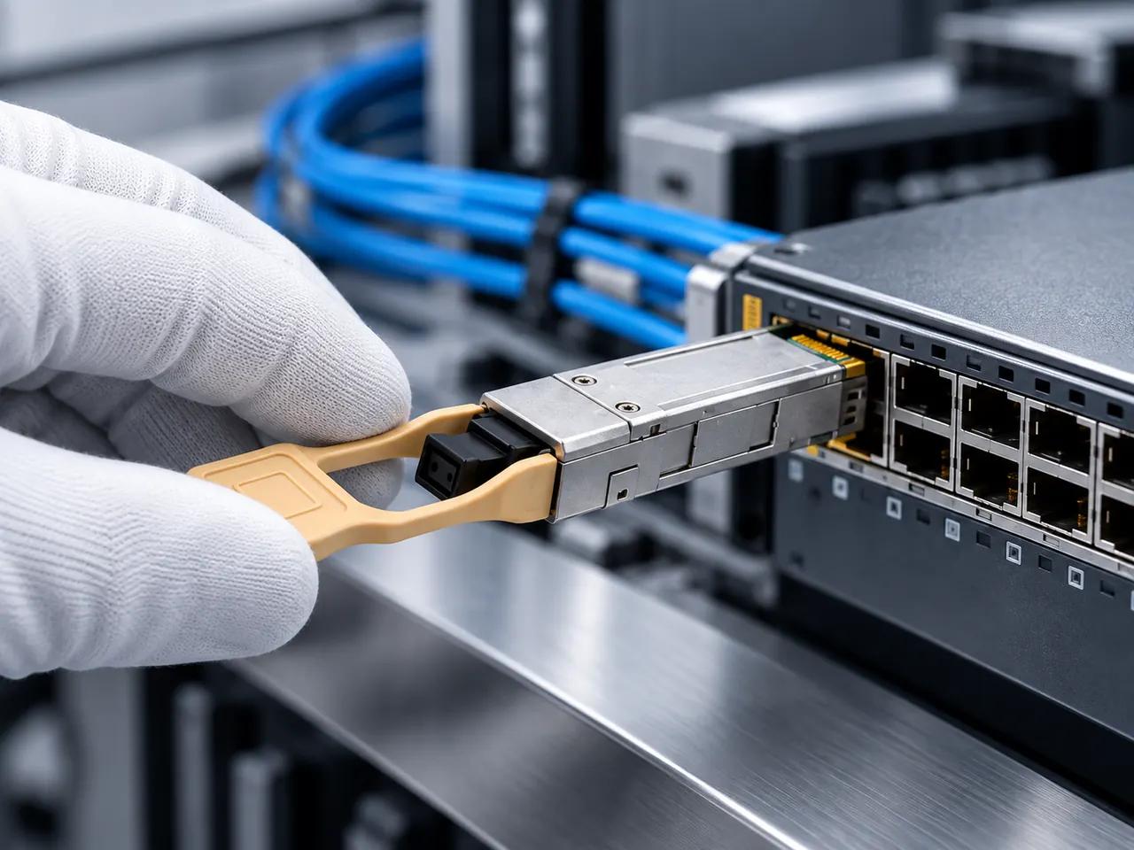
Single mode optical fiber uses an 8.3 to 9.2 µm core to eliminate modal dispersion, enabling terabit-scale transmission across reaches exceeding 100 km at 1310 nm and 1550 nm.
01Single mode optical fiber fundamentals and operating principles
A single mode optical fiber carries light energy along a solitary spatial path, preventing light rays from traversing the core at differing angles. This guided propagation mode eliminates intermodal distortion across extensive spans. Where wide-aperture waveguides support hundreds of reflection pathways, single mode glass guides only the fundamental LP01 (linearly polarised) spatial mode through its central glass core. As a direct consequence, the transmission channel experiences zero differential mode delay, allowing gigabit and multi-gigabit pulses to maintain sharp temporal boundaries across dozens of kilometres without pulse broadening.
Telecommunications networks, enterprise campus backbones, metropolitan transport architectures, and cloud data centre interconnections depend on this single-path characteristic to overcome physical distance limits. For system integrators assessing infrastructure upgrades, deploying single mode fiber cable and optical transceivers provides an optical foundation unconstrained by the modal bandwidth boundaries typical of premises cabling. The optical signal couples directly from narrow-linewidth semiconductor lasers, producing clean, stable wave propagation governed strictly by the refractive index profile of the silicon dioxide silica core and fluorine- or germania-doped cladding.
02Single mode optical fiber core is normally microns in diameter
The single mode optical fiber core is normally microns in diameter, specifically between 8.3 µm and 9.2 µm, encased in a standard 125 µm silica glass cladding. In contrast to human hair, which measures approximately 70 µm across, the sm fiber core size is engineered to match the operational wavelength scale. Because optical energy does not travel exclusively inside the physical core boundary, optical engineers define transmission geometry using mode field diameter (MFD) rather than bare physical core radius. At an operating wavelength of 1310 nm, the MFD of standard ITU-T G.652.D fiber measures 9.2 ± 0.4 µm, expanding to approximately 10.4 ± 0.5 µm at 1550 nm as an electromagnetic evanescent field skims the inner cladding boundary.
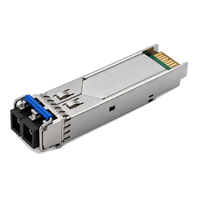
Maintaining strict dimensional tolerance on both the core diameter and core-to-cladding concentricity is vital for structural attenuation control. Under IEC 60793-2-50 standards, core concentricity error must remain below 0.5 µm. If an installer aligns two connectors with a mere 1 µm lateral offset, coupling losses on an 8.3 µm single mode core size exceed 0.5 dB, whereas that identical offset produces negligible attenuation on a 50 µm aperture. Consequently, optical transceivers such as the 1.25G SFP 1310nm SMF 10km optical transceiver employ high-precision zirconia ceramic ferrules to achieve physical axial alignment inside ±0.2 µm tolerances.
03Fiber mode propagation and why modal dispersion disappears
A fiber mode represents an electromagnetic field distribution that satisfies Maxwell's equations and boundary conditions along the cylindrical dielectric waveguide. The number of modes supported by a step-index fiber is determined by its normalized frequency, known in optical physics as the V number:
V = (2π · a / λ) · NA
Where a represents the physical core radius, λ denotes the operational light wavelength, and NA represents the numerical aperture of the fiber, calculated as √(n₁² - n₂²) from the refractive indices of core and cladding. When physical construction restricts the normalized frequency such that V < 2.405, all higher-order spatial modes undergo radiation cut-off. Below this mathematical threshold, only the fundamental HE11 (LP01) mode propagates down the glass strand.
Eliminating higher-order propagation paths fundamentally removes modal dispersion from the transmission channel. In multi-path glass, high-order modes travel along oblique, zigzagging trajectories, taking longer to traverse a given span than on-axis low-order rays. Over distances as short as 300 metres, this modal delay spreads out square digital pulses until binary high and low states overlap into unresolvable intersymbol interference (ISI). In a pure single mode channel, this physical limitation is eliminated, ensuring temporal fidelity across links running upwards of 80 to 120 km.
04Difference between single mode and multimode fiber architecture
The core difference between single mode and multimode glass lies in the core diameter, propagation physics, transmitter sources, and achievable distance-bandwidth metrics. A single mode multi mode evaluation shows that while multimode relies on large 50 µm or 62.5 µm cores illuminated by inexpensive 850 nm Vertical-Cavity Surface-Emitting Lasers (VCSELs), single mode structures demand tight 9 µm channels driven by narrow-linewidth edge-emitting distributed feedback (DFB) or Fabry-Pérot (FP) lasers. These contrasting architectures yield distinctly different operational profiles across local premises, enterprise data centres, and wide-area backbones.
| Engineering Parameter | Single Mode Fiber (OS2) | Multimode Fiber (OM4) | Physical Standard Reference |
|---|---|---|---|
| Core Diameter (µm) | 8.3 to 9.2 | 50.0 ± 2.5 | IEC 60793-2-10 / 50 |
| Cladding Diameter (µm) | 125.0 ± 0.7 | 125.0 ± 1.0 | ITU-T G.652.D |
| Primary Wavelengths (nm) | 1310 / 1490 / 1550 / 1625 | 850 / 1300 | ITU-T G.694.2 |
| Attenuation @ Window (dB/km) | 0.35 @ 1310nm / 0.20 @ 1550nm | 3.00 @ 850nm / 1.00 @ 1300nm | TIA-568.3-D |
| Modal Dispersion | Zero (Single mode cut-off) | Significant (1.5 to 4.7 GHz·km) | ISO/IEC 11801 |
| Typical Transceiver Reach | 2 km to 120 km | 100 m to 400 m | IEEE 802.3 Clauses 38, 52, 88 |
| Standard Cable Jacket Colour | Yellow (OS2) | Aqua / Heather Violet (OM4) | TIA-598-D |
| Light Source Physics | FP / DFB / EML Lasers | 850 nm VCSEL Arrays | SFF-8472 / IEEE 802.3 |
Understanding this difference between multimode fiber and single mode optics prevents costly deployment mistakes. While multimode hardware offers initial cost savings on short interconnects within single equipment racks, multimode singlemode conversions become mandatory whenever runs exceed standard structured cabling limits. For facilities looking to modernise core distribution layers, swapping to single mode cabling eliminates physical upgrade bottlenecks for upcoming 100G, 400G, and 800G line-rate expansions.
05Single mode fiber wavelength windows and spectral attenuation
A single mode fiber wavelength operates across several designated telecommunications optical bands, most notably the Original (O-Band: 1260–1360 nm) and Conventional (C-Band: 1530–1565 nm) spectral regions. Light traversing silica glass experiences intrinsic material losses governed by Rayleigh scattering at shorter wavelengths and infrared phonon vibrational absorption beyond 1600 nm. At 1310 nm, standard ITU-T G.652.D glass exhibits optical attenuation around 0.32 to 0.35 dB/km. At 1550 nm, attenuation drops to its global minimum of 0.18 to 0.22 dB/km, making 1550 nm the optimal carrier window for ultra-long-haul links.
Historically, an intense optical attenuation spike known as the "water peak" occurred around 1383 nm due to trace hydroxyl ion (OH⁻) impurities embedded in the silica matrix during manufacturing. Contemporary G.652.D low-water-peak single mode fiber virtually eliminates this absorption barrier through advanced chemical vapour deposition (CVD) dehydration. Removing this water peak opens the Extended Band (E-Band: 1360–1460 nm), which enables full 18-channel coarse wavelength division multiplexing across grid allocations detailed in our wavelength division multiplexing network guide.
06Single mode speed and data rate scaling across link distances
The single mode speed capability of an installed optical fiber link is mathematically unlimited by modal phenomena, allowing modern transceivers to transmit data rates from 1 Gb/s to over 800 Gb/s per wavelength. Where copper cabling collapses over modest spans due to skin-effect losses and multimode fiber hits strict chromatic and modal delays at 25 Gb/s beyond 100 metres, single mode optics maintain consistent signal fidelity across metro and wide-area spans. Optical channels running multi-lane pulse amplitude modulation (PAM4) and advanced phase modulation scale data density without requiring structural changes to underlying plant glass.
Data rate scaling in single mode infrastructure is governed instead by chromatic dispersion (CD) and polarisation mode dispersion (PMD). In the 1310 nm window, chromatic dispersion hovers near zero (0 to 3.5 ps/(nm·km)), permitting high-baud-rate direct-detection optics, such as 25G and 100G NRZ formats, to travel up to 10–40 km without active dispersion compensation. At 1550 nm, chromatic dispersion climbs to roughly 17 ps/(nm·km), which demands either externally modulated lasers (EML) with tight spectral chirp, electronic dispersion compensation, or advanced digital signal processors (DSPs) for terabit line rates over long routes.
07ITU-T fiber standards: G.652.D vs G.657 bend-insensitive glass
Standard single mode deployments in enterprise backbones and service-provider ducts rely on ITU-T G.652.D fiber, whereas dense cabinets, patch panels, and fiber-to-the-home (FTTH) runs utilise ITU-T G.657 bend-insensitive glass. Standard G.652.D specification prescribes a minimum macrobending radius of 30 mm; tighter bending introduces sharp optical radiation losses where the guided wave leaks outward into the protective cladding. In high-density patching environments, inadvertent cable coiling or hinge pinching quickly causes dropped packets and link degradation.
ITU-T G.657 addresses this routing constraint by introducing a refractive-index trench or depleted nano-engineered cladding layer that reflects light energy back into the central core. Sub-category G.657.A1 reduces the permissible bend radius to 10 mm, G.657.A2 tolerates bends down to 7.5 mm, and extreme G.657.B3 specifications withstand a 5 mm radius without incurring more than 0.1 dB attenuation at 1550 nm. Crucially, G.657.A1 and G.657.A2 fibers retain an identical 9.2 µm mode field diameter and numerical aperture to standard G.652.D glass, guaranteeing seamless, low-loss fusion splicing and cross-patching between outside plant infrastructure and compact high-density rack equipment.
08Optical transceiver modules for single mode fiber links
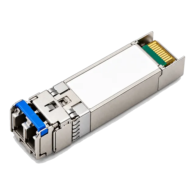
Selecting optical transceiver modules for single mode fiber links requires matching the host port form factor, optical wavelength, reach rating, and laser driver architecture. Small Form-Factor Pluggable (SFP), SFP28, QSFP+, and QSFP28 form factors house internal transmitter optical sub-assemblies (TOSA) with semiconductor laser diodes tailored for specific link lengths. For access networks and enterprise aggregation, modules like the 1.25G Gigabit SFP transceiver deliver reliable 10 km to 120 km connections using standard duplex LC interfaces.
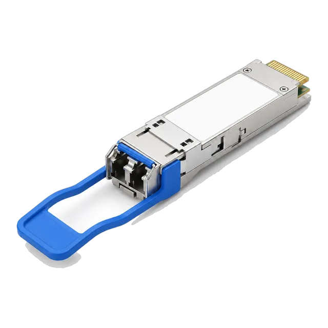
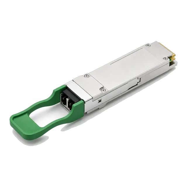
As aggregation tiers scale, engineers transition from legacy Gigabit hardware to 25G and 100G links. Deployments using modules from the 25G SFP28 transceiver series, such as the 25GBASE-LR SFP28 1310nm 10km transceiver, enable direct top-of-rack to spine connectivity across single mode plant. When fiber strand counts are constrained, bidirectional transceivers and coarse division multiplexers optimise utilisation. Integrating systems with options like the 40G QSFP+ LR4 1310nm 10km transceiver or multi-lane 100G QSFP28 CWDM4 2km transceiver enables network teams to multiplex multiple parallel high-speed channels across a single duplex strand pair without pulling new civil cabling.
09Link budget calculation: 25GBASE-LR over 10 km G.652.D fiber
A formal optical link budget calculation proves whether a planned transmitter-receiver pair can operate across a designated single mode fiber span with adequate power margin. The equation sums all deterministic link losses and compares this total against the optical transceiver's dynamic power budget:
Power Margin (dB) = [Tx Power Minimum (dBm) - Rx Sensitivity Minimum (dBm)] - Optical Channel Loss (dB)
Consider an enterprise campus link deploying a 25GBASE-LR SFP28 transceiver conforming to IEEE 802.3by Clause 114 across 10 km of G.652.D single mode fiber, passing through four patch panels (eight mated LC connector pairs) and two fusion splices:
- Transceiver Optical Budget: Minimum Transmit Power (Tx_min) = -7.0 dBm; Maximum Receiver Sensitivity (Rx_sens) = -13.3 dBm. Total available power budget = -7.0 dBm - (-13.3 dBm) = 6.3 dB.
- Fiber Cable Attenuation: 10.0 km × 0.35 dB/km (at 1310 nm) = 3.50 dB.
- Connector Insertion Loss: 8 mated LC/UPC connector interfaces × 0.25 dB per pair = 2.00 dB.
- Fusion Splice Loss: 2 fusion splices × 0.05 dB per splice = 0.10 dB.
- Total Optical Channel Insertion Loss: 3.50 dB + 2.00 dB + 0.10 dB = 5.60 dB.
- Link Operating Margin: 6.30 dB - 5.60 dB = 0.70 dB.
An operating margin of 0.70 dB is functional but narrow for carrier-grade applications, which generally target a 2.0 to 3.0 dB safety margin to accommodate component ageing, patch-lead degradation, and thermal drift. For critical links, an engineer should either select higher-output optics or re-terminate intermediate patch panels with premium low-loss LC connectors rated at 0.10 dB loss per mated pair. Further link design calculations can be modeled via our dedicated optical link budget calculator.
10Testing, inspection, and chromatic dispersion mitigation
Commissioning single mode infrastructure requires strict microscopic end-face inspection and optical time-domain reflectometer (OTDR) verification. Because an 8.3 µm single mode core size occupies an area twenty-five times smaller than a 50 µm multimode core, microscopic contaminants like skin oils, airborne lint, or dust particles directly occlude the optical path. A 5 µm speck of dust that causes minor insertion loss on multimode glass can completely extinguish a single mode beam or induce severe back-reflections that destabilise laser transmitter feedback cavities.
- IEC 61300-3-35 End-Face Inspection: Inspect all connector ferrules using a 400x digital inspection probe. Zone A (the core region from 0 to 25 µm) must show zero scratches, pits, or particulate deposits prior to mating.
- Dual-Wavelength OTDR Characterisation: Test spans bidirectionally at both 1310 nm and 1550 nm. A macrobend signature is instantly exposed if loss at 1550 nm exceeds the loss reading at 1310 nm, as longer wavelengths leak more readily under mechanical stress.
- Optical Return Loss (ORL) Measurement: Ensure all UPC (Ultra Physical Contact) terminations exhibit return loss better than -50 dB, and APC (Angled Physical Contact) interfaces exceed -60 dB to protect sensitive DFB and EML lasers from optical return noise.
11Engineering checklist for single mode transceiver and cable RFQs
Procuring single mode components requires complete optical, mechanical, and environmental specifications to avoid procurement mismatch and site downtime. System integrators and sourcing teams should incorporate the following standardized checklist directly into Requests for Quotation (RFQs):
- Optical Fiber Standard: Specify exact glass geometry and grade (e.g., ITU-T G.652.D for general duct runs, ITU-T G.657.A2 for high-density intra-rack patching).
- Operating Wavelength & Laser Geometry: Declare wavelength requirements (1310 nm FP/DFB for ≤10 km reach, 1550 nm DFB/EML for 40–80 km spans, or CWDM/DWDM grid ITU channels).
- Connector Polish & Ferrule Spec: Specify LC/UPC (blue) for standard enterprise switches or LC/APC (green) for BiDi transceivers, RF video overlay, and passive optical network (PON) splitters.
- Form Factor & Protocol Support: Match device requirements to the host interface (1.25G SFP, 10G SFP+, 25G SFP28, 40G QSFP+, 100G QSFP28) complying with MSA standards (SFF-8431, SFF-8472, SFF-8665).
- Operating Temperature Grade: Commercial Temperature (0°C to +70°C) for air-conditioned data centres; Industrial Temperature (-40°C to +85°C) for outdoor cabinets and roadside switch enclosures.
- Digital Diagnostics Monitoring (DDM/DOM): Mandatory implementation of SFF-8472 internal telemetry, reporting real-time Tx optical power, Rx optical power, operating voltage, bias current, and module temperature.
- Host Platform Compatibility: Require explicit EEPROM coding for the host platform via our transceiver compatibility service, ensuring complete plug-and-play identification without CLI port lockouts.
For custom long-haul spans or tailored transceivers coded to your target hardware, request tailored specifications directly through our technical team on the optical module contact portal.
12Frequently asked questions
What is the primary difference between single mode and multimode fiber?
Single mode fiber has a narrow core (8.3–9.2 µm) carrying light along a single spatial path, eliminating modal dispersion for reaches over 100 km. Multimode fiber uses a 50 µm core, allowing multiple modes that limit transmission to approximately 100–400 m at high data rates.
What is the typical single mode core size?
The physical single mode core size is typically 8.3 to 9.2 microns in diameter, surrounded by a 125-micron cladding. Optical performance is measured by its Mode Field Diameter, which spans approximately 9.2 µm at 1310 nm and expands to 10.4 µm at 1550 nm.
Which wavelengths does single mode fiber use?
Single mode fiber operates primarily at 1310 nm and 1550 nm. The 1310 nm window features near-zero chromatic dispersion for medium-reach enterprise links, while 1550 nm provides the lowest optical attenuation (0.19 dB/km), making it ideal for long-haul and amplified DWDM networks.
Can single mode and multimode fibers be connected directly?
No, single mode and multimode fibers cannot be spliced or mated directly. Connecting a 50 µm multimode launch into a 9 µm single mode core causes massive optical attenuation of 18–20 dB. In the opposite direction, severe modal interference and back-reflections destabilise the link.
Why is yellow the standard colour for single mode fiber cables?
Under the TIA-598-D colour-coding standard, yellow outer jackets denote non-military single mode fiber cables (OS1 and OS2). This universal visual convention allows network engineers to instantly distinguish single mode runs from orange (legacy multimode), aqua (laser-optimized multimode), and magenta (OM4) multimode cabling in crowded racks.
What is the maximum single mode speed for enterprise networks?
Single mode fiber does not impose an upper limit on transmission speed. Modern single mode infrastructure readily supports line rates from 1 Gb/s to 800 Gb/s per wavelength. Actual transmission speed is determined by the transceiver modulation format, electronic signal processing, and optical multiplexing technology.
Technical review note: confirm model-specific specifications with the product datasheet and the intended host documentation. Product images and application photographs are illustrative.
Discuss this with our team