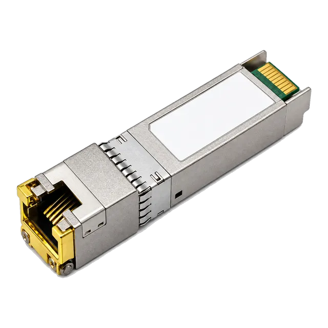
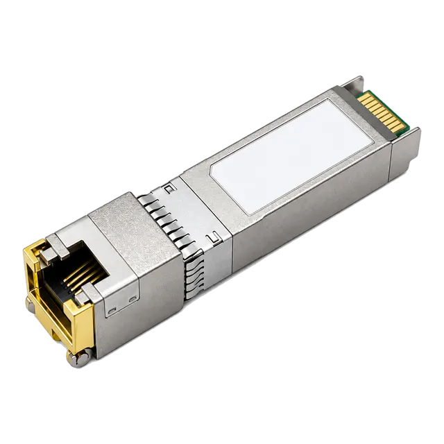
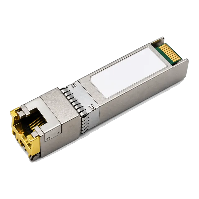
Copper SFP transceivers provide cost-effective RJ45 aggregation over structured twisted-pair cabling, but deployment requires strict management of host SGMII MAC interfaces, thermal load per cage, and cable category transmission parameters.
01What is a copper SFP and how does it convert SGMII to RJ45?
A copper SFP is an MSA-compliant transceiver that translates high-speed serial host data into balanced electrical signals for transmission over unshielded or shielded twisted-pair cabling. In modern enterprise switches and routers, standard Small Form-factor Pluggable (SFP) ports present a Serial Gigabit Media Independent Interface (SGMII) or 1000BASE-X SerDes interface across the 20-pin card-edge connector defined in SFF-8074i. The copper SFP integrates an internal Physical Layer (PHY) integrated circuit and pulse magnetics to convert these serial logic signals into the four-pair multi-level Pulse Amplitude Modulation 5 (PAM-5) encoding mandated by IEEE 802.3ab.
Unlike optical transceivers that rely on laser diodes and photodetectors, a copper module interfaces directly with standard category patch cords terminated in RJ45 plugs. This enables network engineers to connect switches containing purely optical SFP cages into existing structured copper cabling plants without purchasing dedicated fixed-copper line cards. For versatile physical-layer bridging across enterprise networks, deploying an affordable 1000BASE-T SFP copper RJ45 gigabit transceiver allows standard Cat5e and Cat6 patch fields to mate directly with core and distribution switch chassis.
02Copper sfp electrical interface: SerDes, SGMII, and MDI mapping
A copper sfp establishes bidirectional physical communication by converting a host-side differential serial stream into a four-pair balanced Medium Dependent Interface (MDI). On the host PCB side, the transceiver receives high-speed differential transmit data (TD+ and TD-) and outputs differential receive data (RD+ and RD-) at 1.25 Gbps. Within the module enclosure, an ultra-compact PHY transceiver converts the SerDes or SGMII serial stream, separating it into four parallel channels operating at 125 Mbaud per pair.
To support backward compatibility and legacy structured links, the internal PHY operates in either SGMII-to-copper or 1000BASE-X-to-copper pass-through modes. In SGMII mode, the host Medium Access Control (MAC) layer transmits data at clock-divided rates, allowing the PHY to advertise and establish 10BASE-T, 100BASE-TX, or 1000BASE-T auto-negotiation transparently to the host. The MDI output employs integrated isolation transformers and common-mode chokes to suppress electromagnetic interference (EMI) and deliver 1,500 V galvanic isolation compliant with IEEE 802.3 Clause 40.8.3, ensuring signal integrity across cross-connects.
03How does an SFP transceiver 1000BASE-T link negotiate duplex and speed?
An sfp transceiver 1000base t module executes auto-negotiation via physical link pulses exchanged over the copper twisted pairs, independent of the optical SerDes interface. Defined under IEEE 802.3 Clause 28 and Clause 40, 1000BASE-T auto-negotiation exchanges 16-bit fast link pulse (FLP) word patterns known as link code words (LCWs) to resolve operating speed (10/100/1000 Mbps), duplex capability (half or full), and clock configuration (Master/Slave relationship).
For Gigabit transmission, accurate Master/Slave clock assignment is compulsory; one PHY establishes the master reference loop clock, while the link partner aligns its local Phase Locked Loop (PLL) as the slave receiver. If both ports default to forced manual Master configuration, the link will fail to train and drop to link-down status. When evaluating high-density links, specifying an SFP-1G-T 1000BASE-T gigabit copper RJ45 transceiver provides deterministic hardware-driven auto-negotiation that accurately resolves MDI/MDI-X crossover and link timing without manual CLI intervention.
04Physical layer transceiver comparison: 1000BASE-T vs 10GBASE-T copper transceiver
A 10GBASE-T copper transceiver demands substantially higher signal processing complexity, frequency bandwidth, and thermal overhead than a standard Gigabit 1000BASE-T module. While 1000BASE-T uses PAM-5 modulation over a 62.5 MHz Nyquist frequency band to yield 1,000 Mbps, 10GBASE-T adopts PAM-16 encoding with Low-Density Parity Check (LDPC) framing across a 400 MHz bandwidth defined in IEEE 802.3an Clause 55. This multi-level encoding introduces higher computational latency and elevated electrical power draw.
| Metric (Units) | 1000BASE-T SFP | 2.5GBASE-T SFP | 5GBASE-T SFP | 10GBASE-T SFP+ (Cat6a) |
|---|---|---|---|---|
| Standard Clause | IEEE 802.3ab Cl. 40 | IEEE 802.3bz Cl. 126 | IEEE 802.3bz Cl. 126 | IEEE 802.3an Cl. 55 |
| Signalling Rate (Mbaud) | 125 Mbaud/pair | 200 Mbaud/pair | 400 Mbaud/pair | 800 Mbaud/pair |
| Encoding Scheme | PAM-5 | PAM-16 / DSQ128 | PAM-16 / DSQ128 | PAM-16 / DSQ128 |
| Max Reach (m) | 100 m (Cat5e) | 100 m (Cat5ee/Cat6) | 100 m (Cat6) | 30 m to 100 m (Cat6a) |
| Power Dissipation (W) | 0.8 W – 1.05 W | 1.2 W – 1.5 W | 1.5 W – 2.0 W | 2.3 W – 2.7 W |
| Processing Latency (μs) | < 0.1 μs | < 0.5 μs | < 0.8 μs | 1.5 μs – 2.5 μs |
| Host Bus Interface | SGMII / 1000BASE-X | 2500BASE-X | 5GBASE-R / USXGMII | 10GBASE-R (SFF-8431) |
Engineers evaluating high-bandwidth physical infrastructure can deploy the 10G SFP+ copper RJ45 10GBASE-T transceiver for short-distance server connections, provided the host cage meets the elevated Class 3 or Class 4 thermal dissipation profile.
05Thermal dissipation and power budget calculations across switch ports
Thermal dissipation in copper modules significantly exceeds that of standard optical transceivers, requiring thorough chassis thermal budget calculations before port deployment. Standard optical transceivers conforming to SFF-8431 draw between 0.5 W and 1.0 W (Power Level I), while 1000BASE-T copper modules draw approximately 1.05 W and 10GBASE-T modules consume up to 2.7 W.
Consider an enterprise 48-port top-of-rack (ToR) switch equipped with SFP+ cages designed for a maximum power envelope of 1.5 W per port. Populating this switch with 1000BASE-T modules yields the following calculation:
- Individual 1000BASE-T module power: 1.05 W
- Individual 1000BASE-SX optical module power: 0.60 W
- Chassis thermal load for 48 optical ports:
48 × 0.60 W = 28.8 W(98.3 BTU/hr) - Chassis thermal load for 48 copper 1000BASE-T ports:
48 × 1.05 W = 50.4 W(172.0 BTU/hr) - Difference in front-panel thermal dissipation:
50.4 W - 28.8 W = +21.6 W(+75% increase)
If an engineer attempts to populate all 48 ports with 10GBASE-T copper modules rated at 2.5 W each, total front-panel load rises to 48 × 2.5 W = 120.0 W (409.5 BTU/hr). This exceeds standard chassis fan drawer capacities, causing the switch to trigger thermal alarm thresholds and throttle port PHY clocks. To prevent localized hotspots, stagger copper modules across alternate cages or combine them with direct-attach solutions reviewed in our DAC cable engineering guide.
06Cable category requirements: Cat5e, Cat6, and Cat6a distance validation
Structured twisted-pair cable category directly defines maximum operational distance, insertion loss, and alien crosstalk margins for copper SFP modules. Under ISO/IEC 11801 and ANSI/TIA-568-C.2, copper links must maintain strict signal-to-noise ratios (SNR) to avoid link degradation and frame check sequence (FCS) errors.
- Category 5e (Cat5e): Characterized up to 100 MHz. Fully qualified for 1000BASE-T up to 100 metres. Unsuitable for 10GBASE-T due to severe Alien Near-End Crosstalk (ANEXT).
- Category 6 (Cat6): Characterized up to 250 MHz. Supports 1000BASE-T up to 100 metres. Qualified for 10GBASE-T operation only up to 37–55 metres depending on alien crosstalk in tightly bundled raceways.
- Category 6A (Cat6a): Characterized up to 500 MHz with internal pair shielding or augmented outer diameter. Supports both 1000BASE-T and 10GBASE-T up to the full 100-metre structured link limit (90 m permanent link plus 10 m patch cords).
- Category 7 / 7A (Cat7/Cat7a): Characterized up to 600 MHz and 1,000 MHz using individual foil shielding per pair (S/FTP). Guarantees zero alien crosstalk and delivers robust 10GBASE-T operation up to 100 metres in noisy industrial environments.
For additional details regarding copper interface performance versus fiber optic links at the enterprise aggregation tier, consult our analysis on copper vs fiber at the access layer.
07Multi-rate negotiation: auto-media detection and 10/100/1000Base-T PHY modes
Multi-rate copper SFP modules allow a single switch port to dynamically adapt to 10 Mbps, 100 Mbps, or 1000 Mbps end-node equipment without manual re-cabling. This operational flexibility is enabled by an internal PHY that negotiates rate and duplex parameters on the copper MDI side while continuously maintaining a fixed-rate SGMII connection with the host MAC.
When an edge device—such as an industrial programmable logic controller (PLC) or out-of-band management controller—links at 100BASE-TX full duplex, the copper SFP PHY processes the incoming 125 Mbaud MLT-3 signals, decodes the Ethernet frames, and transfers them across the host SGMII interface by repeating clock cycles or utilizing pulse stuffing. For data centres upgrading legacy aggregation hardware, deploying a multi-rate capable transceiver such as the 10G SFP+ copper RJ45 10GBASE-T multi-rate transceiver ensures backward support for 1G, 2.5G, 5G, and 10G speeds across heterogeneous compute nodes.
08Diagnostic monitoring: why DDM and DOM behave differently on copper modules
Digital Diagnostic Monitoring (DDM), also referred to as Digital Optical Monitoring (DOM) under SFF-8472, exhibits significant functional deviations when implemented on copper SFP transceivers compared to optical modules. Optical transceivers utilize internal analog-to-digital converters (ADCs) to report laser bias current, optical transmitter output power (Tx Power), and optical receiver input power (Rx Power). Because a copper module contains no optical transmitter or photodiode, these optical telemetry registers either read zero, present static dummy values, or are omitted entirely from the SFF-8472 memory map.
Instead, copper transceivers utilize the internal registers of the onboard PHY—accessible via the two-wire serial interface (I2C) at address 0xAC or through vendor-specific MII register paging at address 0xA2. These internal registers provide electrical health metrics, including:
- Operating voltage supply (typical 3.3 V rail, monitored ±5%).
- Internal PHY junction temperature (°C).
- Time Domain Reflectometry (TDR) cable diagnostics (detecting open circuits, short circuits, and distance to impedance mismatches).
- Physical layer signal-to-noise margin (SNR) per pair and bit error rate (BER) estimates.
For deeper background on optical diagnostic parameters and register structures, reference our guide on small form factor pluggable module engineering.
09Host EEPROM coding, MSA compliance, and switch compatibility
Switch operating systems identify and configure copper SFP modules by reading the standardized 256-byte EEPROM memory structure defined in SFF-8024 and SFF-8472 at I2C address 0xA0. When a module is inserted, the switch reads byte 0 (Identifier: 0x03 for SFP/SFP+), byte 2 (Connector: 0x22 for RJ45), and bytes 3–10 (Transceiver Compliance Codes: bit 3 of byte 6 set to 1 indicates 1000BASE-T compliance).
However, many enterprise host platforms enforce proprietary microcode checks. If the Vendor Name (bytes 20–35), Vendor OUI (bytes 37–39), Part Number (bytes 40–55), and cyclic redundancy check (CRC) checksums in byte 63 or byte 95 do not match expected vendor hashes, the host will assert an "unsupported transceiver" software block or disable the PHY clock output. To ensure seamless plug-and-play operation, transceivers must be encoded with host-specific configuration headers. For an exhaustive breakdown of EEPROM byte maps, checksum routines, and vendor masking, review our technical guide on transceiver coding and EEPROM compatibility.
10Port density limits: mitigating EMI and thermal throttling in adjacent cages
Populating contiguous SFP cages with copper transceivers creates physical constraints related to electromagnetic interference, connector tab clearance, and air channel obstruction. The integrated metal shield of an RJ45 SFP module houses internal high-frequency pulse transformers, generating magnetic field fringing that can couple into adjacent cages if shielding gaskets are degraded.
Furthermore, standard RJ45 modular jack dimensions (13.7 mm width) leave minimal lateral clearance within standard 14.25 mm pitch SFP cage assemblies. When 24 or 48 copper transceivers are installed contiguously, the mechanical release latches can jam against adjacent connector shrouds, making maintenance challenging without specialised extraction tools. To optimize thermal airflow and prevent adjacent EMI coupling, follow these engineering practices:
- Limit copper transceivers to a maximum of 50% density across high-density switch blocks, alternating copper modules with passive optical transceivers or empty slots.
- Ensure front-to-back chassis cooling fans maintain a static pressure of at least 150 Pa across the line card cage assembly.
- Verify that all RJ45 patch cables utilize snagless boots that do not impinge on neighboring SFP extraction bails.
11Troubleshooting copper links: link flap, duplex mismatch, and cable faults
Troubleshooting copper SFP link failures requires a systematic physical and logical isolation process to distinguish between cabling faults, auto-negotiation protocol mismatches, and transceiver PHY hangs. When a copper SFP fails to establish a stable link, execute the following isolation procedure:
- Inspect physical link indicators: Check switch port LED states. An unlit LED indicates loss of physical carrier pulses (Clause 28 FLP absence) or lack of power to the internal PHY.
- Audit port speed and duplex configurations: Ensure both endpoints are set identically. If one side is set to Auto-Negotiation and the partner is hardcoded to 1000 Mbps Full Duplex, the link partner will fail to complete parallel detection, causing link flap or half-duplex fallback.
- Execute TDR cable diagnostics: Use switch CLI commands (e.g.,
test cable-diagnostics tdr) to measure loop resistance and locate impedance disruptions. A return code showing "Open" or "Short" within 2 metres indicates a defective RJ45 termination or damaged patch cord. - Verify host SerDes matching: Ensure the switch port SFP cage is configured for
speed 1000ormedia-type sfp. Forcing an SFP+ port to run at 10G when a 1G copper module is inserted will prevent SerDes lock. - Inspect transceiver operating temperature: Query internal registers. If the PHY temperature exceeds 85°C, thermal shutdown has occurred, necessitating improved rack airflow or port redistribution.
12RFQ specification checklist for enterprise and ISP procurement
Procuring copper transceivers for large-scale enterprise or telecommunications deployments requires an unambiguous bill of materials to avoid delivery of incompatible hardware. Paste the following specification parameters directly into procurement requests:
- Transceiver Form Factor: SFP (1 Gbps) or SFP+ (10 Gbps), conforming strictly to SFF-8431 and SFF-8074i.
- Target Protocol: IEEE 802.3ab 1000BASE-T (or IEEE 802.3an 10GBASE-T / IEEE 802.3bz 2.5G/5GBASE-T).
- Physical Connector: Fully shielded RJ45 female receptacle with integrated EMI spring fingers.
- Operating Reach: 100 metres over Cat5e/Cat6 for 1 Gbps; or specified reach (30 m, 80 m, or 100 m) over Cat6a/Cat7 for 10 Gbps.
- Host Interface Mode: SGMII (with 10/100/1000BASE-T auto-negotiation support) or SERDES 1000BASE-X pass-through.
- Maximum Power Consumption: ≤ 1.05 W per module for 1G; ≤ 2.5 W per module for 10G across full temperature range.
- Operating Temperature Grade: Commercial (0°C to +70°C) or Industrial (-40°C to +85°C).
- EEPROM Coding: Target host switch platform vendor, model, and software release version explicitly stated.
- Compliance & Safety: RoHS-6 compliant, CE mark, FCC Class B, and UL 94 V-0 flammability rating for internal PCB and plastic mouldings.
13Specifying copper transceivers for your deployment architecture
Selecting the correct transceiver architecture requires evaluating physical infrastructure reach, host chassis thermal envelopes, and structured cabling performance. For network architects managing mixed optical and copper infrastructures, browsing our broad portfolio of copper RJ45 SFP transceivers provides access to reliable 1 Gbps and 10 Gbps options built to MSA specifications. Whether connecting high-density aggregation switches, top-of-rack storage nodes, or edge access switches, engineering the physical layer correctly ensures deterministic network uptime.
Before finalising volume procurement orders, evaluate engineering sample units within your staging laboratory against our sample evaluation plan to verify physical inter-port clearance, DDM reporting, and host CLI recognition under live traffic conditions.
14Frequently asked questions
Can I plug a copper SFP into any optical SFP port?
Yes, provided the host switch SFP port supports standard 1.25 Gbps SGMII or 1000BASE-X SerDes interfaces and the chassis thermal design can handle the 1.05 W power load. Some switch vendors require specific port configuration commands to switch from optical to copper PHY mode.
Why does a 10GBASE-T SFP+ draw more power than an optical transceiver?
A 10GBASE-T SFP+ module draws 2.3 W to 2.7 W because its internal PHY must run complex digital signal processing (DSP) for echo cancellation, crosstalk suppression, and PAM-16 LDPC decoding. In contrast, 10G optical modules merely convert logic levels into photonic pulses, consuming under 1.0 W.
What is the maximum cable distance supported by a 1000BASE-T copper SFP?
The maximum standard reach for a 1000BASE-T copper SFP is 100 metres over Category 5e, Category 6, or Category 6a unshielded or shielded twisted-pair cabling. This distance comprises a 90-metre horizontal permanent link and up to 10 metres of total patch cord length.
Why does my switch CLI show no Tx or Rx power for a copper SFP?
Copper SFP modules do not contain optical lasers or photodetectors, so optical power registers under SFF-8472 read as zero, N/A, or fixed dummy data. Physical layer health on copper links is assessed via link state, bit error rate, and time-domain reflectometry instead.
Can a 10GBASE-T copper SFP auto-negotiate down to 1 Gbps or 100 Mbps?
Only multi-rate 10GBASE-T copper transceivers support auto-negotiation down to 1 Gbps, 100 Mbps, or 2.5G/5G speeds. Standard fixed-rate 10GBASE-T modules operate exclusively at 10 Gbps and will fail to link if connected to a legacy 1000BASE-T switch port.
Technical review note: confirm model-specific specifications with the product datasheet and the intended host documentation. Product images and application photographs are illustrative.
Discuss this with our team