Reliable 1000BASE-T performance requires all four twisted pairs compliant with Category 5e or higher over a maximum 100-metre channel, balancing insertion loss, crosstalk and DC loop resistance for data and Power over Ethernet deployments.
01Physical layer requirements for a gigabit ethernet cable
A compliant gigabit ethernet cable operates across four balanced twisted pairs using 1000BASE-T modulation defined by IEEE 802.3ab Clause 40. Achieving full-duplex transmission at 1000 Mbps requires a symbol rate of 125 MBd per pair using five-level pulse amplitude modulation (PAM-5), which yields an aggregate throughput of 1 Gbps across the four pairs. Unlike Fast Ethernet (100BASE-TX), which functions over two pairs using one pair for transmission and one pair for reception, every modern cable for 1gb ethernet transmits and receives simultaneously on all eight copper conductors through digital signal processor (DSP) hybrid cancellation circuits.
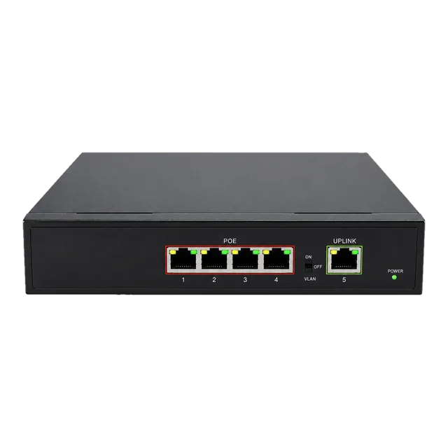
The physical medium relies on 100-ohm balanced twisted-pair infrastructure defined by ANSI/TIA-568.2-D and ISO/IEC 11801 Class D standards. When connecting an edge device to a Gigabit PoE IP Ethernet Switch, the maximum permanent link distance is 90 metres of solid horizontal cable, supplemented by up to 10 metres of stranded patch cord to preserve signal integrity and stay within the 100-metre total channel envelope. Deviating from balanced electrical parameters or introducing poor punch-down terminations alters characteristic impedance, inducing return loss that prevents PHY transceivers from maintaining stable gigabit synchronisation.
02Which connection type can support gigabit ethernet
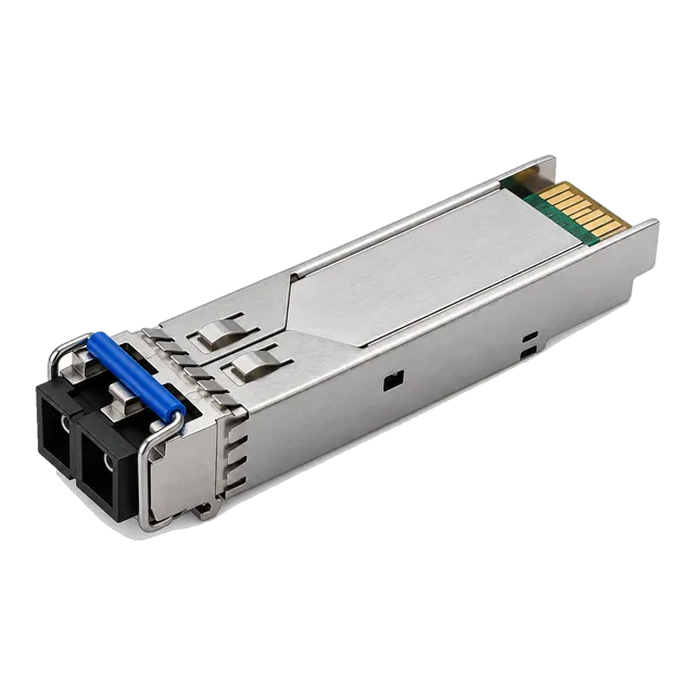
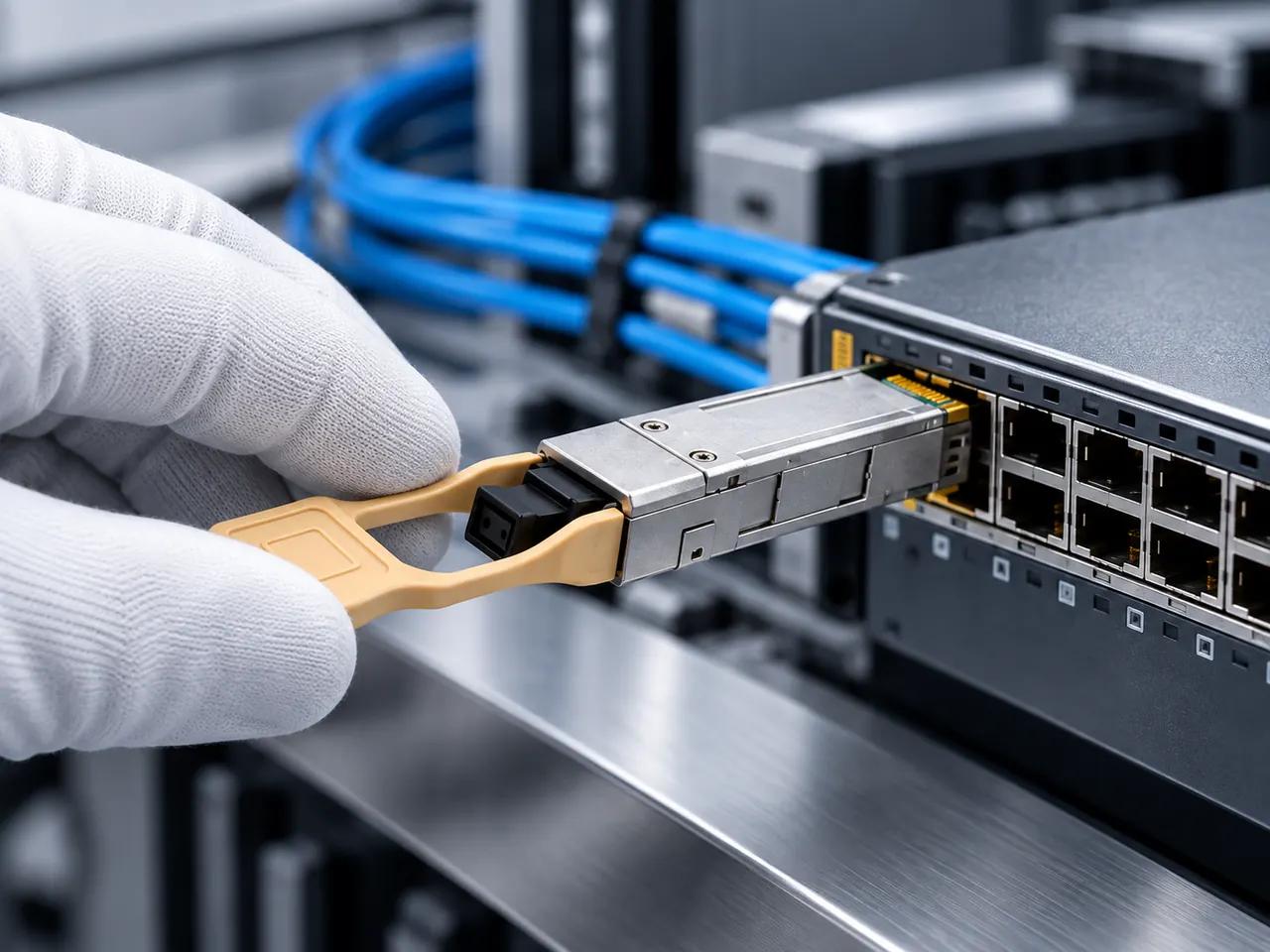
Three primary connection types can support gigabit ethernet: twisted-pair copper cabling terminating in 8P8C (RJ45) modular connectors, multimode or single-mode optical fibre terminating in LC or SC connectors, and twinaxial direct attach copper assemblies. The standard twisted-pair copper gigabit network cable provides native compatibility with host switch ports up to 100 metres at lowest capital cost per port. For campus aggregation or electromagnetic interference (EMI) prone routes, optical fibre interfaces use small form-factor pluggable transceivers running 1000BASE-SX or 1000BASE-LX over distances from 220 metres to 10 kilometres, as detailed in our guide on 1000BASE LX SFP transceivers.
For intra-rack patching between adjacent top-of-rack switches and storage arrays, passive direct attach copper (DAC) or modular copper transceivers bridge physical layers without running full structured runs. When specifying a network upgrade, determining which connection type can support gigabit ethernet depends directly on channel distance, environmental noise, power delivery requirements and existing switch port hardware interfaces.
03Category ratings and gigabit network cable performance
Category 5e, Category 6 and Category 6a cables all support ethernet gigabit transmission at 100 metres, but they provide different frequency headroom and immunity against signal degradation. Category 5e is certified to 100 MHz, matching the minimum baseline required by 1000BASE-T; however, Category 6 increases bandwidth certification to 250 MHz and Category 6a reaches 500 MHz. This expanded bandwidth reduces bit error rates (BER) caused by near-end crosstalk (NEXT) and attenuation-to-crosstalk ratio far-end (ACRF).
| Metric (at 100 MHz) | Category 5e | Category 6 | Category 6a |
|---|---|---|---|
| Certified Bandwidth (MHz) | 100 | 250 | 500 |
| Maximum Insertion Loss (dB/100m) | 24.0 | 21.3 | 20.8 |
| NEXT Loss Minimum (dB) | 30.1 | 39.9 | 44.3 |
| PS-ACRF Minimum (dB) | 14.4 | 24.8 | 27.8 |
| Max Channel Length for 1 Gbps (m) | 100 | 100 | 100 |
| Max Channel Length for 10 Gbps (m) | Not Supported | 37 – 55 | 100 |
Deploying Category 6 or 6a for a 1gb network cable plant adds physical resilience and headroom against future 2.5G, 5G and 10GBASE-T network upgrades without rewiring horizontal conduits, making it the preferred choice for enterprise building infrastructure.
04Twisted-pair copper vs optical fiber for 1gb ethernet
Twisted-pair copper delivers cost-effective terminal distribution up to 100 metres with Power over Ethernet (PoE) capability, whereas optical fibre delivers galvanic isolation and transmission reaches reaching 100 kilometres without signal repeaters. In a typical gigabit ethernet network, copper patch cords and horizontal channels service end devices such as desktop hosts, wireless access points and security cameras. Optical fibre serves as the riser and building backbone where channel lengths exceed 100 metres or span outdoor ducts between disparate grounding systems.
Optical links running on transceivers such as the 1.25G SFP 1310nm 10km Transceiver bypass external electromagnetic noise generated by heavy industrial machinery, high-voltage variable frequency drives and adjacent power conduits. Optical fibre also reduces transmission latency by avoiding complex multi-level PAM processing and echo-cancellation latency intrinsic to copper PHY silicon. Detailed architectural comparisons can be found in our review of copper or fiber at the access layer.
05Calculating link margin and insertion loss across structured cabling
A compliant 1000BASE-T copper link requires total channel insertion loss below 21.0 dB at 100 MHz across the full 100-metre envelope according to ANSI/TIA-568.2-D. Channel insertion loss incorporates horizontal solid-core cable, stranded-core patch cords, modular jack connections and cross-connect patch panels. Solid 24 AWG horizontal cable exhibits approximately 0.21 dB of attenuation per metre at 100 MHz, whereas 26 AWG stranded patch cable incurs approximately 20% to 50% higher attenuation (roughly 0.28 dB per metre) due to skin effect and stranded conductor geometry.
Consider an enterprise permanent link consisting of 85 metres of Cat6 solid horizontal cable, two 5-metre Cat6 stranded patch cables, and four connector interfaces (two patch panel ports, two wall outlets). We calculate the total channel loss as follows:
- Horizontal cable loss: 85 m × 0.21 dB/m = 17.85 dB
- Patch cord loss: 10 m × 0.28 dB/m = 2.80 dB
- Connector loss (four RJ45 jacks): 4 × 0.20 dB = 0.80 dB
- Total channel insertion loss: 17.85 + 2.80 + 0.80 = 21.45 dB
Because 21.45 dB exceeds the 21.0 dB budget at 100 MHz, this channel fails certification testing and risks packet drop or intermittent down-negotiation. Shortening horizontal copper runs or upgrading patch leads to lower-loss 24 AWG conductors restores total attenuation to 19.55 dB, yielding an operational headroom of 1.45 dB.
06PoE delivery over 1gb lan cable runs
Power over Ethernet injects DC current over balanced twisted-pair copper conductors concurrently with 1 Gbps differential data symbols without degrading Ethernet gigabit throughput. IEEE 802.3af (PoE, Type 1, 15.4 W source) and IEEE 802.3at (PoE+, Type 2, 30.0 W source) apply phantom power using centre-tapped isolation transformers across two or four pairs, while IEEE 802.3bt (Type 3 and Type 4) energises all four pairs up to 90 W to supply high-draw devices such as PTZ surveillance cameras and multi-band Wi-Fi 6/7 access points.
Conductor resistance causes internal I²R thermal dissipation in dense cable bundles, increasing cable core temperature and raising signal attenuation. For every 10°C increase above 20°C, insertion loss across Category 5e and Category 6 UTP rises by approximately 4% to 6%, shortening the allowable channel reach from 100 metres down to 88 metres under maximum thermal loading. Using pure annealed copper conductors rather than copper-clad aluminium (CCA) is mandatory; CCA presents higher DC loop resistance, leading to excessive voltage drop across long runs and severe heat buildup that damages jacket jackets. Review power sizing rules in our PoE switch standards and power budget guide.
07Shielded vs unshielded cable for 1gbps ethernet networks
Unshielded twisted-pair (U/UTP) cabling relies entirely on pair twist symmetry to reject differential noise, whereas shielded constructions incorporate metallic foil or braided screens to isolate pairs from external RF interference. In standard enterprise commercial spaces, U/UTP provides sufficient common-mode rejection for any 1 gigabit ethernet cable drop. However, industrial plants, hospital imaging suites and dense datacentre runs require shielded variants such as F/UTP (overall foil screen) or S/FTP (braided outer screen with individual foil pairs) to eliminate electromagnetic pickup and alien crosstalk (ANEXT).
Shielded cable requires continuous, low-impedance bonding to building telecommunications grounding infrastructure at both ends according to ANSI/TIA-607-D. Floating, broken or poorly terminated shields act as unintended antennas, collecting stray electromagnetic fields and degrading signal-to-noise ratios. Furthermore, potential differences between remote ground points create ground loop currents over the shield, introducing 50/60 Hz hum and digital packet corruption across the gigabit lan network.
08Connecting a gigabit ethernet port with copper SFP modules
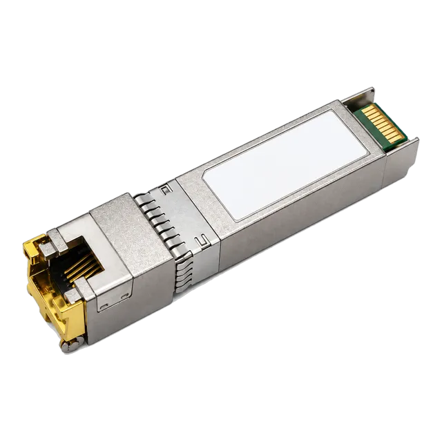
A switch equipped with small form-factor pluggable cages connects directly to standard copper patch infrastructure using a modular 1000BASE-T transceiver like the SFP-1G-T 1000BASE-T Gigabit Copper RJ45 Transceiver. The internal PHY converts the switch host's SGMII (Serial Gigabit Media Independent Interface) into balanced 1000BASE-T differential electrical signals over an integrated RJ45 receptacle. This architecture enables network operators to expand copper connectivity on fiber-dominated aggregation switches without changing physical switch hardware.
The power envelope of a copper transceiver is approximately 1.0 to 1.2 W, which is higher than standard optical transceivers (approx. 0.5 to 0.8 W) due to DSP complexity and line drivers. When populating consecutive SFP ports in high-density switches, verify the thermal budget of the chassis to prevent local port overheating. For further details on module architectures, see our copper SFP transceiver engineering guide.
09Troubleshooting gb ethernet speed degradation and autonegotiation drops
When a link negotiates at 100 Mbps Fast Ethernet instead of the expected gb ethernet speed, the underlying issue is almost always an open pair, high return loss or physical pinout damage. IEEE 802.3ab autonegotiation checks for physical continuity across all four wire pairs (1-2, 3-6, 4-5, 7-8). If pair 4-5 or 7-8 is damaged, open, or incorrectly split during termination, the switch and endpoint PHYs gracefully fall back to 100BASE-TX, which only requires pairs 1-2 and 3-6 to pass basic link pulses.
- Verify wire mapping at both patch terminations using a calibrated time-domain reflectometer (TDR) to rule out split pairs and open pins.
- Check the physical connector for recessed, corroded, or bent contacts inside the gigabit ethernet port.
- Inspect channel length; runs exceeding 100 metres exhibit excessive high-frequency roll-off, inducing link training failures during the PAM-5 echo-cancellation phase.
- Ensure standard T568A or T568B pinout consistency on both ends; mixing standards on a non-MDI/MDI-X link creates excessive near-end crosstalk.
- Review port error counters using switch CLI to identify CRC errors, fragment frames, or carrier transitions indicating damaged patch leads.
10Enterprise gigabit lan network architectural design
A robust gigabit lan network topology follows hierarchical structured cabling design principles codified by TIA-568.0-E, separating access distribution from core uplinks. Horizontal cabling from individual floor distributors (telecommunications rooms) delivers dedicated gigabit ethernet cable runs to work area RJ45 outlets. Switches located in edge distribution racks aggregate end-user ports and provide uplink connectivity toward the network core through high-speed fibre pairs or multi-gigabit uplinks.
To avoid bottlenecks, access layer switches must balance client port density against uplink backplane capacity. An access switch hosting 48 copper 1 Gbps ports generates an aggregate edge line rate of 48 Gbps full duplex. Providing dual 10 Gbps SFP+ uplinks yields an acceptable 2.4:1 oversubscription ratio for typical enterprise corporate environments, ensuring line-rate switching without frame drops during peak workstation data transfers, file server backups and high-resolution video streams.
11Engineering checklist for gigabit ethernet cable procurement
Procuring structured cabling and patch assemblies for enterprise or carrier infrastructure requires rigid mechanical and electrical specifications to guarantee longevity. Use this specification checklist when preparing a formal request for quotation (RFQ) for any project requiring high-density cable ethernet 1gbps deployments:
- Conductor Material: 100% solid electrolytic bare copper for horizontal bulk cable; oxygen-free stranded copper for patch cords. Explicitly reject copper-clad aluminium (CCA).
- Conductor Gauge: Minimum 24 AWG for horizontal Category 5e/Cat6; 23 AWG preferred for Category 6/6a; 24–26 AWG for patch assemblies.
- Jacket Fire Rating: Low Smoke Zero Halogen (LSZH, IEC 60332-1 / IEC 61034) for European and UK public installations; CMR (Riser) or CMP (Plenum, NFPA 262) for North American building codes.
- Pinout Standards: 100% factory-terminated patch cables wired to ANSI/TIA-568.2-D T568B configuration.
- Connector Plating: 50 micro-inches (1.27 µm) gold plating over 100 micro-inches nickel on RJ45 contact pins to prevent oxidisation and fretting corrosion under PoE current.
- Verification Testing: Mandatory permanent link and channel certification reports meeting TIA Cat6 / ISO Class E limits with full sweep data from 1 to 250 MHz.
12Frequently asked questions
which connection type can support gigabit ethernet
Gigabit Ethernet is supported by balanced twisted-pair copper cabling (Cat5e, Cat6, Cat6a) terminating in RJ45 connectors via 1000BASE-T, multimode optical fibre (OM1 to OM5) via 1000BASE-SX, single-mode optical fibre via 1000BASE-LX/ZX, and direct attach copper assemblies for intra-rack equipment patching.
can cat5 cable run gigabit ethernet speed
Standard legacy Cat5 cable is not certified for 1 Gbps operation. While it uses four pairs, its crosstalk and return loss specifications were only validated to 100 MHz for 100BASE-TX. Reliable 1000BASE-T operation requires Category 5e (enhanced) or higher to prevent transmission errors and speed downgrades.
what is the maximum distance for a gigabit ethernet cable run
The maximum standard distance for a copper gigabit Ethernet run is 100 metres (328 feet). This channel envelope consists of a maximum 90-metre horizontal solid-core permanent link plus up to 10 metres of total stranded patch cable distributed between both ends.
why does my gigabit connection only show 100 mbps
A connection dropping to 100 Mbps indicates an open circuit, severed conductor or split pair among pins 4, 5, 7, or 8. Gigabit Ethernet requires all four copper pairs to train properly. If any pair fails continuity or exhibits excessive crosstalk, the PHY automatically renegotiates down to 100BASE-TX.
does poe reduce gigabit ethernet cable speed
No, Power over Ethernet does not reduce data throughput when deployed on standards-compliant cabling. PoE injects common-mode DC power over the conductors via centre-tapped transformers, which is transparent to the high-frequency differential AC signals carrying the 1 Gbps Ethernet data streams.
is cat6 better than cat5e for gigabit networks
Yes, Cat6 provides tighter pair twists, a central spline and 250 MHz testing, providing superior signal-to-noise ratio, less crosstalk, and lower insertion loss. While both support 1 Gbps up to 100 metres, Cat6 provides operational headroom and future-proofs infrastructure for 2.5GBASE-T and 5GBASE-T.
Technical review note: confirm model-specific specifications with the product datasheet and the intended host documentation. Product images and application photographs are illustrative.
Discuss this with our team