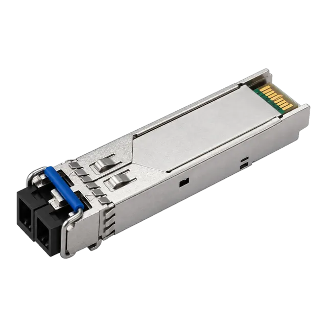
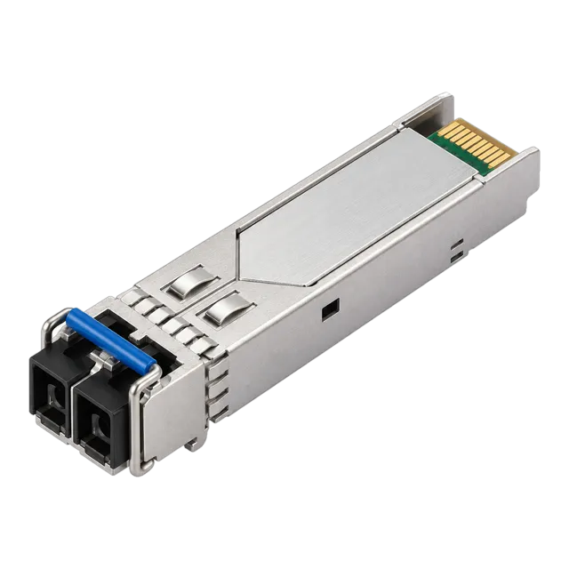
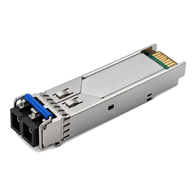
The 1000BASE LX standard provides 1.25 Gbps transmission over 10 km on single-mode fibre and 550 m on legacy multimode fibre, delivering dependable, low-power Gigabit connectivity when engineered with proper link budgets and host coding.
01What is a 1000BASE LX SFP optical transceiver?
A 1000BASE LX optical transceiver is a modular physical layer device defined by IEEE 802.3z Clause 38 that transmits Gigabit Ethernet at 1.25 Gb/s over optical fibre using long-wavelength 1310 nm optics. Built into the hot-pluggable Small Form-Factor Pluggable (SFP) form factor governed by SFF-8431 and SFF-8472, the 1.25G SFP architecture interfaces a host switch's Serial Gigabit Media Independent Interface (SGMII) or 1000BASE-X serdes directly to an optical plant. Modern deployments rely on the 1000base lx sfp to bridge access aggregation switches, industrial remote terminal units, building backbones, and telecom demarcation points across distances up to 10 km on standard single-mode fibre.
Internally, a standard 1000base lx sfp module incorporates a 1310 nm semiconductor transmitter—typically a Fabry-Perot (FP) laser diode—coupled to a monitor photodiode, alongside an Indium Gallium Arsenide (InGaAs) PIN receiver matched with a transimpedance amplifier (TIA). Optical termination is provided via an industry-standard duplex LC receptacle conforming to IEC 61754-20. By operating in the second telecommunications transmission window where silica fibre exhibits near-zero chromatic dispersion, the module maintains clean eye diagrams over link distances that vastly exceed legacy copper or short-wavelength multimode limits.
02Technical specifications: optical parameters and IEEE 802.3z standards
Optical parameters for 1000BASE-LX are formally specified under IEEE 802.3z Table 38-7 and Table 38-8, establishing strict power levels, spectral widths, and receiver sensitivities across 10 km of single-mode plant.
| Parameter | IEEE 802.3z Minimum | Typical Commercial Value | IEEE 802.3z Maximum | Units |
|---|---|---|---|---|
| Data Rate | 1.25 | 1.25 | 1.25 | Gb/s |
| Centre Wavelength (λ) | 1270 | 1310 | 1355 | nm |
| Spectral Width (RMS) | — | 1.5 | 4.0 | nm |
| Average Launch Power | -11.0 | -9.0 to -3.0 | -3.0 | dBm |
| Receiver Sensitivity (BER 10⁻¹²) | — | -21.0 to -20.0 | -19.0 | dBm |
| Receiver Overload (Damage Threshold) | -3.0 | -3.0 | 0.0 | dBm |
| Extinction Ratio | 9.0 | 10.0 to 12.0 | — | dB |
| Optical Return Loss Tolerance | 12.0 | 14.0 | — | dB |
While the baseline IEEE standard sets an optical power budget of 8.0 dB (-11.0 dBm minimum launch to -19.0 dBm receiver sensitivity), modern transceivers such as the 1.25G SFP Transceiver Module 1310nm 10/20km Duplex LC DDM feature refined PIN receivers providing -20.0 dBm or better sensitivity. This gives network engineers substantial margin against dirty connector end-faces, micro-bends, and high-loss mechanical splices.
031000BASE LX vs 1000BASE SX: core engineering differences
The core difference between 1000BASE-LX and 1000BASE-SX lies in the operating wavelength, light source, and physical transmission media specified in IEEE 802.3z. 1000BASE-SX operates at 850 nm utilising low-cost Vertical-Cavity Surface-Emitting Lasers (VCSELs) restricted entirely to multimode fibre (OM1 through OM5), achieving reach profiles between 220 m and 550 m. In contrast, 1000BASE-LX employs a 1310 nm Fabry-Perot laser designed natively for 9/125 μm single-mode fibre (ITU-T G.652), extending transmission to 10 km or 20 km.
For enterprise campus designers, choosing an sfp lx over an SX optic standardises the access and distribution tiers onto single-mode outside plant (OSP), eliminating the bandwidth-distance product limitations inherent to multimode cores. Furthermore, 1000BASE-LX retains backward compatibility with existing multimode infrastructure via mode conditioning patch leads, making it a universal consolidation choice for brownfield campus backbones.
04Transmission distance on single-mode vs multimode fibre
A standard 1000base lx sfp delivers a reach of 10,000 m over standard OS2 single-mode fibre and up to 550 m across legacy 50 μm or 62.5 μm multimode fibre. The exact distance capability depends strictly on the modal bandwidth of the physical glass and the total optical attenuation across the link path.
| Fibre Type | Core Diameter (μm) | Modal Bandwidth (MHz·km @ 1310 nm) | Maximum Standard Reach (m) | Mode Conditioning Required? |
|---|---|---|---|---|
| OS1 / OS2 Single-Mode | 9.0 | Infinite (dispersion limited) | 10,000 (up to 20,000 extended) | No (Standard LC patch cord) |
| OM1 Multimode | 62.5 | 500 | 550 | Yes (Mandatory per IEEE 802.3z) |
| OM2 Multimode | 50.0 | 500 | 550 | Yes (Mandatory per IEEE 802.3z) |
| OM3 Multimode | 50.0 | 500 | 550 | Recommended if link exceeds 150 m |
| OM4 / OM5 Multimode | 50.0 | 500 | 550 | Recommended if link exceeds 150 m |
Extended-reach variants, frequently classified by manufacturers as 20 km models like the 100% Compatible 1.25G SFP Module SM 1310nm 20km Duplex LC, incorporate higher-output FP lasers and tighter receive optics to achieve a 14 dB optical budget, comfortably spanning regional utility and inter-building spans without mid-span repeaters.
05Why mode conditioning patch cords are required on legacy MMF
Mode conditioning patch cords are mandatory when operating a 1310 nm 1000baselx sfp over legacy 62.5/125 μm (OM1) or 50/125 μm (OM2) multimode fibre because of Differential Mode Delay (DMD). When a narrow, highly collimated single-mode laser beam is launched directly into the exact geometric centre of a graded-index multimode core, it excites contradictory, uncalibrated spatial modes. These central core imperfections cause light pulses to split, travel down distinct paths at variable group velocities, and arrive at the receiver spread across time, inducing severe intersymbol interference (ISI) and elevated bit error rates (BER).
A Mode Conditioning Patch (MCP) cable remedies this phenomenon by integrating an off-centre fusion splice between a single-mode pigtail and a multimode launch fibre. This physical splice induces a calibrated lateral offset of 4 μm to 7 μm for 50 μm MMF, or 17 μm to 23 μm for 62.5 μm MMF, as governed by IEEE 802.3z Clause 38.11.4. The offset launch excites a symmetrical distribution of higher-order modes throughout the core, eliminating the central mode differential and guaranteeing clean transmission up to the 550 m specification limit.
06Calculating an optical link budget for 1000BASE LX
Calculating an optical power budget ensures that an optical transmitter delivers sufficient signal to the receiver after accounting for all passive distribution losses and operational safety margins. The link budget calculation follows a deterministic equation:
Available Link Budget (dB) = Minimum Tx Optical Power (dBm) − Receiver Sensitivity (dBm)
Total Channel Insertion Loss (dB) = (α × L) + (N_c × Loss_c) + (N_s × Loss_s) + Safety Margin
Consider a 12.0 km campus inter-site link deployed over ITU-T G.652.D OS2 single-mode fibre, using a 10/20 km optic such as the 1.25G SFP 1310nm SMF Dual-Fiber Optical Transceiver 10km:
- Transceiver Min Tx Power: -9.0 dBm
- Transceiver Max Rx Sensitivity: -20.0 dBm
- Available Power Budget: -9.0 − (-20.0) = 11.0 dB
- Fibre Cable Attenuation (α @ 1310 nm): 0.35 dB/km × 12.0 km = 4.2 dB
- Optical Connectors (N_c = 4 mated LC pairs @ 0.30 dB/pair): 1.2 dB
- Fusion Splices (N_s = 6 splices @ 0.08 dB/splice): 0.48 dB
- Engineering Operating Margin (component ageing, repair splices): 3.0 dB
- Total Channel Attenuation: 4.2 + 1.2 + 0.48 + 3.0 = 8.88 dB
Because the total calculated attenuation of 8.88 dB is less than the available optical power budget of 11.0 dB, the link delivers an excess operational headroom of 2.12 dB, confirming viable, error-free physical transmission. For detailed link loss verification against dynamic parameters, use our optical link budget calculator.
071000BASE LX vs 1000BASE LX/LH: clarifying marketing nomenclature
The distinction between 1000BASE-LX and 1000BASE-LX/LH is purely a commercial branding convention rather than an independent IEEE 802.3 working group standard. While IEEE 802.3z officially codifies only "1000BASE-LX" for 10 km transmission over SMF, multiple original equipment manufacturers coined the term 1000base lx lh sfp ("Long Haul") to signify modules engineered with superior transmitter power margins capable of traversing 10 km to 20 km over single-mode fibre, while maintaining full mode-conditioned compliance on 550 m multimode lines.
In procurement documents, an lx sfp module labelled as LX/LH serves as a direct functional replacement for an IEEE 1000BASE-LX optic. The underlying hardware utilises standard 1310 nm optics, identical pinouts under the SFP Multi-Source Agreement (MSA), and identical 8B/10B physical coding sublayer (PCS) signalling. Buyers should focus on verified minimum transmitter launch power and optical receiver sensitivity rather than the LH marketing suffix.
08Form factor and mechanical design: SFP MSA compliance
A 1000base lx sfp transceiver adheres to the Small Form Factor Multi-Source Agreement outlined in SFF-8431, INF-8074i, and SFF-8024, ensuring uniform physical dimensions and electrical interfaces across equipment manufacturers. The module measures 8.5 mm in height, 13.4 mm in width, and 56.5 mm in length, designed for dense edge chassis integration with standard cage pitch dimensions.
The physical interface consists of a 20-pin edge connector providing differential transmit (TD+/TD−) and receive (RD+/RD−) high-speed lines, low-speed I2C communications (SCL/SDA), transmitter disable (Tx_Disable), rate select, and loss-of-signal (Rx_LOS) status lines. Standard modules run on a single 3.3 V ± 5% DC supply rail and consume under 0.8 W of electrical power under nominal loads. Mechanics include a bail-clasp, slider, or pull-tab latching mechanism designed to withstand a minimum of 100 hot-plug mating cycles without degrading cage pin spring tension or optical connector alignment.
09Digital Diagnostic Monitoring (DDM / DOM) operational thresholds
Digital Diagnostic Monitoring (DDM), alternatively designated as Digital Optical Monitoring (DOM) under SFF-8472, provides internal physical operating data via an I2C serial master reading a slave 2-wire interface at address A2h. The subsystem continuously samples and reports five internal operating telemetry points: internal module temperature (°C), internal supply voltage (V), laser bias current (mA), transmitted optical power (Tx Power in dBm/μW), and received optical power (Rx Power in dBm/μW).
| Monitored Telemetry Parameter | High Alarm Limit | High Warning Limit | Low Warning Limit | Low Alarm Limit | Engineering Diagnosis |
|---|---|---|---|---|---|
| Internal Temperature (°C) | > +85.0 | > +75.0 | -5.0 | < -10.0 | Thermal dissipation failure or fan tray fault |
| Supply Voltage (V) | > 3.60 | > 3.47 | < 3.13 | < 3.00 | Host power delivery or chassis backplane drop |
| Laser Bias Current (mA) | > 45.0 | > 35.0 | < 5.0 | < 2.0 | Laser diode ageing or end-of-life degradation |
| Tx Optical Power (dBm) | > -2.0 | > -3.0 | < -9.5 | < -11.0 | Transmitter launch loss or optical subassembly shift |
| Rx Optical Power (dBm) | > -1.0 | > -3.0 | < -19.0 | < -21.0 | Patch lead contamination, cable pinch, or OSP break |
To inspect detailed diagnostic commands and interpret operational readings in live chassis, refer to our guide on what DDM can tell you about an optical link.
10Host platform compatibility and EEPROM programming
Host platform acceptance of a 1000base lx sfp depends on the vendor-specific data written into the transceiver's 256-byte serial EEPROM memory located at I2C address A0h. While the physical hardware connects seamlessly to any compliant SFP receptacle, switch operating systems interrogate bytes 0 through 95—governed by the SFF-8024 and SFF-8472 specifications—to verify vendor identifiers, serial numbers, date codes, transceiver capability flags, and cryptographic checksums.
Switch vendors employ distinct internal verification routines:
- Header Checksums: Byte 63 contains a bitwise checksum of bytes 0 to 62; byte 95 contains a checksum of bytes 64 to 94. Any byte change without updating these values marks the module as corrupt.
- Vendor OUI Verification: Switch firmware compares bytes 37 to 39 (Vendor IEEE Company ID / OUI) against proprietary whitelists.
- Security Signatures: Several enterprise equipment lines interrogate high-memory blocks above address 128 for vendor-signed digital certificates. If verification fails, the switch port transitions to an
err-disabledstate.
For unmanaged or legacy systems, hardware-agnostic coding allows universal link establishment. However, mission-critical infrastructure mandates precise, vendor-coded EEPROM programming to display native CLI inventory, support serial number tracking, and eliminate command-line override flags like service unsupported-transceiver. System integrators should review our technical article on how transceiver coding works: EEPROM, MSA, and host support.
11Industrial vs commercial temperature grades for harsh environments
Transceivers deployed in uncontrolled environments require ruggedised internal components to prevent thermal breakdown, laser spectral drift, and early infant mortality. 1000BASE-LX modules are produced across two core thermal grading classes:
- Commercial Temperature (C-Temp): 0°C to +70°C (32°F to 158°F), designed for standard enterprise data centres, wiring closets, and climate-controlled equipment rooms.
- Industrial Temperature (I-Temp): -40°C to +85°C (-40°F to 185°F), mandatory for roadside cabinets, substations, trackside rail networks, and outdoor oil and gas SCADA architectures.
Operating a standard C-temp module inside an outdoor roadside enclosure exposes the optical transmitter to thermal degradation. At elevated temperatures, the central emission wavelength of an FP laser drifts upwards at approximately 0.4 nm/°C. An unhardened laser operating at +80°C drifts past its design spectrum, causing high dispersion and decreased optical output power. Industrial-grade 1000BASE-LX transceivers use burn-in-tested semiconductor lasers, internal thermistors with temperature-compensated bias controllers, and rugged gold-plated pin surfaces to deliver continuous 1.25 Gb/s throughput throughout harsh operational cycles.
12Step-by-step troubleshooting: diagnosing link-down and high BER
Systematic diagnostic procedures allow engineers to isolate optical, physical, or protocol faults efficiently when establishing a 1000BASE-LX link.
- Inspect Physical Link LEDs and CLI Status: Run
show interface statuson the host switch. Confirm whether the port indicatesDown/Down,Administratively Down, orErr-Disabled. - Verify Optical Polarity: Ensure the transmit (Tx) port of local optic A routes directly to the receive (Rx) port of remote optic B. If link status is down, invert the duplex LC connector pair on one patch lead end to clear a crossed transmit-to-transmit error.
- Read DDM Diagnostic Values: Interrogate DDM telemetry via
show interfaces transceiver detail. If Tx optical power reads lower than -9.5 dBm, suspect internal laser failure. If Rx optical power reads below -20.0 dBm, excessive line attenuation exists. - Clean and Scope All Ferrule End-Faces: Dust particles measuring 1 μm can block single-mode cores entirely. Inspect all patch cord connectors and transceiver ports with a 400x optical fibre scope. Clean with a 1.25 mm dry-click cleaner and IPA wipes, observing IEC 61300-3-35 cleanliness criteria.
- Verify Insertion Loss with an Optical Power Meter: Disconnect the remote LC connector at the receiver and measure actual arriving power at 1310 nm using a calibrated optical power meter. Verify the power level falls inside the normal operating window (-19.0 dBm to -3.0 dBm).
- Check Host Interface Configuration: Ensure auto-negotiation settings match on both switch endpoints. Mismatched flow control, manual speed configuration, or forced duplex parameters on 1000BASE-X links will prevent link establishment.
131000BASE LX SFP procurement checklist and RFQ specification
When generating a Request for Quotation (RFQ) for bulk procurement of 1000base lx sfp transceivers, procurement managers and network engineers must specify exact operational parameters to ensure component reliability and cross-platform compatibility.
| Procurement Parameter | Required Specification | Integrator Notes |
|---|---|---|
| Standard & Data Rate | 1000BASE-LX, 1.25 Gbps SGMII / 1000BASE-X | IEEE 802.3z Clause 38 compliant |
| Optical Form Factor | SFP (Small Form-Factor Pluggable) | Duplex LC receptacle, INF-8074i / SFF-8431 |
| Operating Wavelength | 1310 nm nominal (1270 nm to 1355 nm band) | Fabry-Perot (FP) laser source |
| Target Transmission Distance | 10 km (Standard) or 20 km (Extended Headroom) | Specifies optical link budget (9.0 dB to 14.0 dB) |
| Fibre Media Compatibility | 9/125 μm Single-Mode (ITU-T G.652.D / G.657.A1) | Multimode (legacy multimode fibre) via MCP cable |
| Optical Transmitter Power | -9.0 dBm to -3.0 dBm | Class 1 Laser Eye Safety (IEC 60825-1) |
| Receiver Sensitivity & Overload | Sensitivity: ≤ -20.0 dBm; Overload: ≥ -3.0 dBm | PIN photodiode array |
| Digital Diagnostics | DDM / DOM enabled | SFF-8472 Rev 12.x compliant |
| Operating Temperature Grade | Commercial (0°C to +70°C) or Industrial (-40°C to +85°C) | Match to equipment installation environment |
| Target Host Compatibility | Pre-programmed per vendor platform | Specify exact host switch model and OS version |
| Regulatory Compliance | RoHS-6, CE, FCC Part 15 Class B | Verified manufacturing quality standards |
To configure your bill of materials or request target platform coding, contact our optical engineering team directly at optical module procurement inquiries or consult our transceiver selector tool.
14Frequently asked questions
What is 1000BASE LX?
1000BASE LX is an IEEE 802.3z physical layer standard for Gigabit Ethernet over fibre. It uses long-wavelength 1310 nm optics to transmit 1.25 Gbps data streams across single-mode fibre spans up to 10 km, as well as legacy multimode fibre networks up to 550 m.
Can I use 1000BASE LX on multimode fibre?
Yes, 1000BASE LX operates over legacy 62.5 μm and 50 μm multimode fibre up to 550 m. When connecting to OM1 or OM2 multimode plant, you must use a mode conditioning patch cord on both ends to eliminate Differential Mode Delay and maintain link stability.
What is the difference between 1000BASE LX and 1000BASE LH?
1000BASE LX is the official IEEE 802.3z standard defining 10 km reach. 1000BASE LH is a vendor marketing term for 'Long Haul' transceivers featuring higher transmitter output and sensitive receivers that achieve 20 km over single-mode fibre while remaining fully backward-compatible with 1000BASE LX.
Does a 1000BASE LX SFP need an optical attenuator for short runs?
No, a standard 10 km 1000BASE LX SFP does not require an optical attenuator on short patch runs. The maximum launch power of -3.0 dBm matches the receiver overload threshold of -3.0 dBm, ensuring the optical detector will not saturate or sustain optical damage.
What wavelength does a 1000BASE LX SFP use?
A 1000BASE LX SFP operates at a nominal centre wavelength of 1310 nm, with an IEEE 802.3z defined spectral operating window spanning 1270 nm to 1355 nm. This wavelength matches the zero-dispersion window of standard ITU-T G.652 single-mode optical fibre.
Is a 1000BASE LX SFP compatible with an SFP+ 10G port?
A 1000BASE LX SFP can work in an SFP+ port only if the host switch hardware and firmware support dual-rate 1G/10G operation. Many switch ports support manual configuration to 1000 Mbps speed, while other dedicated 10G-only ports reject 1G modules.
Technical review note: confirm model-specific specifications with the product datasheet and the intended host documentation. Product images and application photographs are illustrative.
Discuss this with our team