Selecting a PoE switch requires matching IEEE 802.3 power classes and total thermal dissipation to peak load across structured copper cabling, whilst planning uplink optics for non-blocking backhaul.
01What is a PoE switch and how does it deliver power?
A poe switch is a network bridge that injects direct-current electrical power alongside Ethernet data frames across structured twisted-pair cabling. In modern enterprise and industrial environments, deploying a poe switch eliminates the requirement for dedicated alternating-current (AC) mains outlets at remote device locations. The switch functions as Power Sourcing Equipment (PSE), delivering direct-current (DC) voltage to a Powered Device (PD) such as a Voice over IP (VoIP) telephone, pan-tilt-zoom (PTZ) surveillance camera, or Wi-Fi 6/6E wireless access point (WAP).
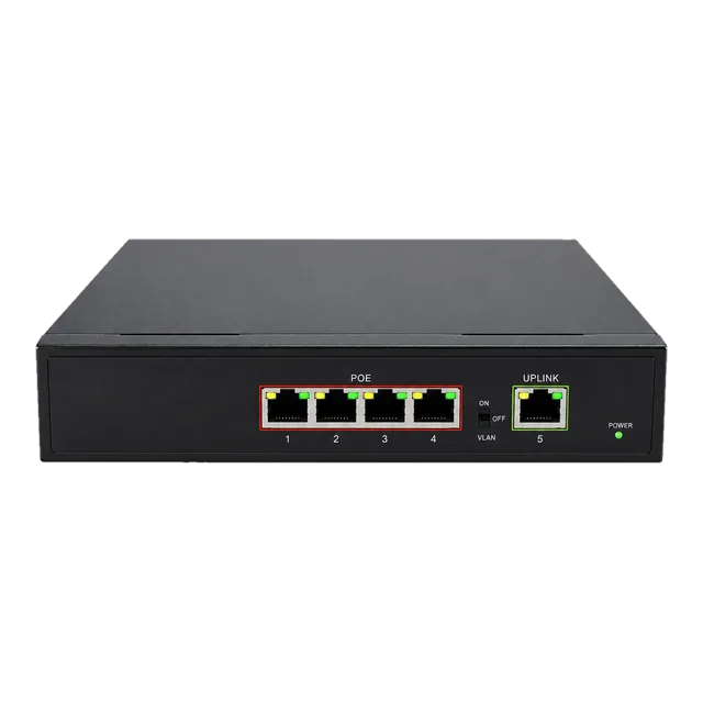
Power injection occurs through phantom feeding, where DC bias is applied to the center taps of Ethernet isolation transformers without corrupting high-frequency differential data signals. Under IEEE standards, data and power coexist on the same copper conductors using common-mode voltage biasing. A basic entry model such as the Gigabit PoE IP Ethernet Switch — 4 PoE Ports + 1 Uplink provides standard 48 V nominal DC injection directly over Category 5e (Cat5e) or Category 6 (Cat6) cabling, establishing deterministic power delivery within a compact footprint.
02PoE standards: IEEE 802.3af, 802.3at, and 802.3bt compared
Standardised Power over Ethernet relies on IEEE 802.3 specifications that define power sourcing limits, voltage tolerances, and conductor utilisation. IEEE 802.3af (Type 1) delivers up to 15.4 W per port at the PSE, IEEE 802.3at (PoE+, Type 2) scales delivery to 30.0 W, and IEEE 802.3bt (4PPoE, Type 3 and Type 4) extends power delivery across all four twisted pairs up to 60 W and 90 W respectively.
| Standard | IEEE Type | Conductor Pairs | PSE Output Power (W) | PD Minimum Power (W) | Nominal Voltage (V DC) |
|---|---|---|---|---|---|
| IEEE 802.3af | Type 1 | 2-pair (Alternative A or B) | 15.4 | 12.95 | 44.0 – 57.0 |
| IEEE 802.3at | Type 2 | 2-pair (Alternative A or B) | 30.0 | 25.50 | 50.0 – 57.0 |
| IEEE 802.3bt | Type 3 | 4-pair (or 2-pair) | 60.0 | 51.00 | 50.0 – 57.0 |
| IEEE 802.3bt | Type 4 | 4-pair | 90.0 | 71.30 | 52.0 – 57.0 |
Selecting a power over ethernet switch demands auditing the physical layer capability of the PD. A Type 2 switch port operates with reverse compatibility, providing 15.4 W to legacy 802.3af devices while reserving 30 W for 802.3at terminals. When deploying multi-sensor infrared cameras or building automation controllers, choosing a Type 4 poe enabled switch ensures that 71.3 W remains accessible at the end of a 100-metre structured link after accounting for DC loop resistance losses.
03Calculating power budget on a power over ethernet switch
A power over ethernet switch must possess an internal power supply unit (PSU) whose total wattage exceeds the aggregate peak draw of all connected powered devices plus cabling thermal dissipation. Sizing an installation based on average consumption invites intermittent port resets during initialisation or automated operational cycles such as nocturnal infrared illumination activation.
Consider a 24-port poe network switch supporting twelve Class 4 (802.3at, 30 W allocation) outdoor PTZ cameras and twelve Class 3 (802.3af, 15.4 W allocation) access control terminals over 90-metre Cat6 horizontal runs. To calculate total required capacity:
- Peak PSE load for Class 4 devices: 12 ports × 30.0 W = 360.0 W
- Peak PSE load for Class 3 devices: 12 ports × 15.4 W = 184.8 W
- Aggregate baseline port allocation: 360.0 W + 184.8 W = 544.8 W
- Operational safety margin (20% headroom for inrush current and ambient thermal derating): 544.8 W × 1.20 = 653.76 W
Under this deployment profile, specifying a switch with an integrated 740 W power supply guarantees continuous uptime without port deprioritisation. System engineers should also configure Link Layer Discovery Protocol (LLDP) Power via MDI (IEEE 802.3 Clause 79), permitting the PSE and PD to negotiate dynamic power delivery in 0.1 W increments rather than relying purely on static hardware classification.
04PoE switch vs PoE injector vs PoE hub: architecture differences
A dedicated poe ethernet switch consolidates multi-port Layer 2 or Layer 3 packet switching with integrated power sourcing circuitry, whereas a midspan injector or legacy poe hub separates data bridging from power insertion. Midspan injectors insert power between a non-PoE switch and a field terminal, acting as transparent two-port series devices.
A legacy poe hub aggregates power injection over multiple ports without managing packet traffic at Layer 2, often presenting an unmanaged midspan physical topology. While a midspan injector solves the isolated requirement of powering a solitary access point from an existing core switch, scaling to dozens of drops creates cable clutter and increases failure points. Implementing a rack mount poe switch concentrates power distribution, backup battery integration, and port management within an individual chassis, streamlining operations and reducing mean time to repair (MTTR).
05PoE powered switch and passthrough operation in remote cabinets
A poe powered switch draws its operational electrical energy directly from an upstream PSE port over structured copper cabling, functioning as a Powered Device itself. These compact units—frequently designated as an ethernet switch powered by poe—eliminate the necessity for local mains outlets inside utility shafts, ceiling plenums, and external junction enclosures.
When an installation demands cascading power to downstream endpoints, a poe powered poe switch (or PoE passthrough switch) receives high-wattage power—typically via IEEE 802.3bt 60 W or 90 W—and partitions the incoming wattage between its internal switching silicon and secondary output ports. For example, a poe powered network switch receiving 71.3 W of usable PD power at the end of a 100-metre Cat6a line consumes 8 W for its switching logic and reserves the remaining 63.3 W to drive two downstream 802.3at endpoints. Deploying a poe powered gigabit switch in this manner simplifies remote expansion while adhering to strict electrical isolation standards.
06Gigabit switch power over ethernet: transmission limits and cabling
A gigabit switch power over ethernet delivers 1000BASE-T transmission over four balanced twisted pairs simultaneously while superimposing DC power over the exact same copper media. Under TIA-568 and ISO/IEC 11801 standards, channel length is strictly constrained to 100 metres (90 metres of solid horizontal cable plus 10 metres of stranded patch cords).
High-power operation induces Joulean heating within dense cable bundles, which elevates channel attenuation and accelerates insulation degradation. According to IEEE 802.3bt guidelines, continuous delivery of Type 4 (90 W) power causes bundle core temperatures to rise by more than 10 °C if bundle sizes exceed 24 cables without adequate spacing. Deploying Category 6A cabling with 23 American Wire Gauge (AWG) solid conductors reduces DC resistance to approximately 6.5 Ω per 100 metres per conductor loop, compared to 14.0 Ω in standard 26 AWG Cat5e. Lower DC loop resistance reduces thermal build-up and minimises voltage drop across the 100-metre run, securing reliable operation for a poe switch gigabit ethernet deployment.
07Active PoE vs passive PoE: electrical signalling and device safety
Active PoE adheres to IEEE 802.3af/at/bt specifications and implements an active handshake protocol before applying operating voltage, whereas passive PoE applies continuous, unregulated direct current across specific pairs without handshaking. An active power over ethernet poe switch applies a low-voltage detection probe (2.7 V to 10.1 V) to measure whether a 25 kΩ signature resistance exists within the connected terminal.
If the 25 kΩ signature is absent, the active PSE port withholds voltage, ensuring that connecting a non-PoE network interface card (NIC) or test instrument causes zero electrical damage. Passive PoE systems, frequently operating at 24 V DC over spare pairs (pins 4, 5 positive; pins 7, 8 negative), supply voltage immediately upon physical insertion. Connecting a standard non-isolated network card to a passive port frequently results in permanent silicon failure. For mission-critical infrastructure, deploying an active poe capable switch is essential to prevent accidental electrical destruction during patch panel maintenance.
08Optical uplink integration: bridging a PoE ethernet switch to campus fibre
Bridging a poe ethernet switch to a core network backbone requires optical uplink ports to overcome the 100-metre physical limitation of copper structured cabling. Enterprise access switches incorporate Small Form-factor Pluggable (SFP) or SFP+ transceivers, routing aggregated endpoint traffic back to core aggregation routers via single-mode or multimode optical links.
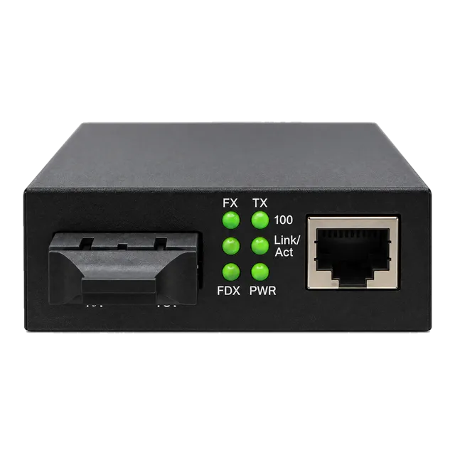
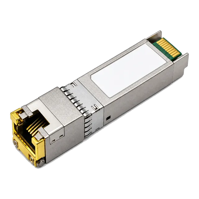
Where local switch power is available but field devices lack copper reach, pairing switches with a 1.25G SFP UTP PoE Media Converter enables long-distance optical transmission with local 30 W PoE injection over the terminal copper drop. For aggregation uplinks operating at 1.25 Gb/s over single-mode fibre, network engineers install MSA-compliant optical modules such as the Affordable 1000BASE-T SFP Copper RJ45 for inter-switch copper patching, or dedicated single-mode optics. When specifying optical modules for outdoor cabinets housing a switch with poe power, engineers should review our guide on buying optics for outdoor, industrial and PoE deployments to match industrial operating temperatures (-40 °C to +85 °C).
09Thermal management and rack mount PoE switch deployment
A rack mount poe switch concentrates substantial thermal output within an enclosed data cabinet, requiring rigorous airflow engineering and thermal calculations. The thermal dissipation of a PoE switch equals the sum of its internal chassis baseline heat load and the internal efficiency losses of its high-capacity power supply operating under full current draw.
Power supply conversion efficiency typically ranges between 88% and 92%. In a switch delivering 480 W of DC power across 16 ports with a 90% efficient internal PSU, approximately 53.3 W of heat is dissipated directly inside the switch chassis from power conversion alone, in addition to roughly 40 W from switching silicon and PHY transceivers. The resulting total heat rejection reaches 93.3 W (318.3 BTU/hr). Proper rack design requires leaving 1U of ventilation spacing between densely loaded PoE switches or utilising thermostatically controlled exhaust fans to prevent localized thermal throttling and capacitor degradation.
10Selecting between managed and unmanaged PoE network switch architectures
A managed poe network switch provides granular port-level control, telemetry, and isolation protocols, whereas an unmanaged switch delivers transparent plug-and-play forwarding without administrative visibility. In enterprise deployments, managed platforms enable network administrators to configure priority queues, IEEE 802.1Q virtual local area networks (VLANs), and Simple Network Management Protocol (SNMP) traps.
Managed switches also introduce remote power cycling. If an edge IP camera or wireless AP becomes unresponsive, an administrator can execute an isolated port-level power bounce via Command Line Interface (CLI) or Web GUI, resetting the physical terminal without dispatching a field technician. Furthermore, managed switches permit dynamic power allocation using priority metrics (Critical, High, Low). If main utility power drops and the switch transitions to uninterruptible power supply (UPS) battery operation, non-essential poe switch port assignments can be shed automatically to prolong runtime for critical life-safety and communication channels.
11Industrial and outdoor deployments: power over ethernet network switch hardening
A hardened power over ethernet network switch deployed in roadside cabinets, railway corridors, or sub-stations must withstand extreme ambient temperatures, high electromagnetic interference (EMI), and severe electrical transients. Commercial-grade switches fail prematurely in these settings due to capacitor drying and solder fatigue under thermal cycling.
Hardened industrial switches comply with IEC 61850-3 and IEEE 1613 specifications, featuring fanless IP40-rated aluminium enclosures that operate reliably between -40 °C and +75 °C. Because outdoor cameras and perimeter sensors are highly susceptible to indirect lightning strikes and electrostatic discharge (ESD), industrial PoE ports incorporate 6 kV surge protection on both data lines and DC power pairs conforming to IEC 61000-4-5. For installations bridging to regional distribution points, engineers must also model overall channel losses by reviewing our optical link budget calculation guide and referencing our comparison in copper or fiber at the access layer.
12Engineering checklist for specifying a PoE switch in procurement RFQs
Specifying a poe switch for commercial or municipal tenders requires unambiguous electrical, optical, and protocol definitions to avoid receiving under-rated hardware. When drafting a Request for Quotation (RFQ), procurement teams should tabulate explicit criteria covering PSE class capabilities, backplane bandwidth, uplink form factors, and environmental tolerances.
| Evaluation Criterion | Specification Standard / Parameter | Procurement Verification Requirement |
|---|---|---|
| PoE Capability | IEEE 802.3af / 802.3at / 802.3bt | Explicit declaration of maximum per-port wattage and standard compliance |
| Total Power Budget | Watts (W) at operating temperature | Gross usable power budget sustained at 50 °C without derating |
| Switching Capacity | Gigabits per second (Gbps) / Mpps | Non-blocking wire-speed forwarding across all access and uplink ports |
| Uplink Interfaces | SFP / SFP+ / SFP28 cages | MSA compliance, DDM telemetry support, single-mode and multimode flexibility |
| Layer 2/3 Feature Set | IEEE 802.1Q, 802.1p, LLDP-MED | Dynamic power negotiation, remote port power cycle, and IGMP snooping |
| Surge & EMC Isolation | IEC 61000-4-5, Level 3 or 4 | Common-mode and differential-mode surge suppression ratings (e.g., 6 kV) |
| Operating Temperature | Commercial (0 to 50 °C) vs Industrial (-40 to +75 °C) | Full factory burn-in test documentation across rated thermal envelope |
To finalise system specifications or verify optical transceiver compatibility across disparate host switches, use our online link budget calculator or consult with our technical sales engineers via the contact page.
13Frequently asked questions
What is the difference between PoE, PoE+, and PoE++?
PoE (IEEE 802.3af) delivers up to 15.4 W per port, PoE+ (IEEE 802.3at) provides up to 30 W, and PoE++ (IEEE 802.3bt) supplies up to 60 W (Type 3) or 90 W (Type 4). Higher standards utilize all four cable pairs to power demanding devices like PTZ cameras and high-capacity wireless access points.
Can a PoE switch damage a non-PoE device?
An active PoE switch complying with IEEE 802.3af/at/bt will not damage non-PoE devices. It conducts a low-voltage detection test before supplying power; if no 25 kΩ signature resistance is detected, power is withheld. However, passive PoE supplies continuous voltage without negotiation and can destroy standard network cards.
How far can a PoE switch transmit power and data?
Standard PoE delivers data and power up to 100 metres (328 feet) over Cat5e, Cat6, or Cat6a cabling, as defined by IEEE 802.3 and TIA-568 standards. Distances beyond 100 metres require PoE extenders, dedicated long-range transmission modes that reduce data rates, or hybrid copper-fibre solutions.
What is a PoE powered switch?
A PoE powered switch is an edge switch that draws its operational electrical power directly from an upstream PoE switch or injector via an Ethernet cable, functioning as a Powered Device. Some models feature passthrough capabilities, allowing them to power downstream devices without requiring local AC mains electricity.
How do you calculate the required PoE power budget?
Sum the maximum rated wattage of all connected powered devices, add calculated cable resistance losses, and append a 20% operating safety margin. For example, twelve 30 W PoE+ devices require 360 W of port power; applying a 20% margin indicates a switch power supply of at least 432 W.
Does a PoE switch consume maximum power continuously?
No, a PoE switch only supplies the power demanded by connected devices at any given moment. An 802.3at port capable of 30 W will supply only 5 W if connected to an idle IP phone, dynamically scaling consumption based on real-time device load.
Technical review note: confirm model-specific specifications with the product datasheet and the intended host documentation. Product images and application photographs are illustrative.
Discuss this with our team