Selecting the right optical wavelength requires balancing fiber attenuation and chromatic dispersion against transceiver component costs across the 850 nm, 1310 nm, and 1550 nm spectral transmission windows.
01Optical transmission windows in silica glass
Selecting the correct fiber optic wavelengths is essential for balancing signal attenuation, chromatic dispersion, and transceiver transceiver component costs across modern telecommunications infrastructure. Standard silica glass optical fibre does not transmit all light frequencies equally; instead, physical phenomena such as Rayleigh scattering, infrared absorption, and hydroxyl ion (OH-) water-peak absorption dictate specific spectral ranges where optical signals propagate with minimal loss. These operational regions are designated as optical transmission windows under International Telecommunication Union (ITU-T) standards.
The first window, centred at 850 nm, was historically adopted due to the commercial availability of early gallium arsenide (GaAs) light-emitting diodes (LEDs) and silicon detectors, despite exhibiting relatively high attenuation of approximately 2.5 dB/km. The second window, operating at 1310 nm, exploits the naturally occurring zero-dispersion wavelength of standard 2.5G single-mode 1310nm transceivers, reducing attenuation to roughly 0.35 dB/km. The third window at 1550 nm offers the lowest attenuation achievable in silica glass, typical of 0.20 dB/km, making it the bedrock of long-haul and dense wavelength division multiplexing networks.
02Standard fiber optic wavelengths across optical transmission bands
Standard fiber optic wavelengths are organised by the ITU-T into six discrete spectral bands spanning the single-mode transmission spectrum from 1260 nm to 1675 nm. Understanding these band definitions enables network architects to specify transceivers that match the optical properties of their installed outside plant.
The six spectral bands defined under ITU-T G.694 comprise the following ranges:
- O-Band (Original, 1260 nm – 1360 nm): Characterised by zero material dispersion in standard single-mode fibre, widely used for datacom, enterprise campus backbones, and 100GBASE-LR4 links.
- E-Band (Extended, 1360 nm – 1460 nm): Historically avoided due to severe water-peak attenuation at 1383 nm, but unlocked in modern ITU-T G.652.D low-water-peak fibres for Coarse Wavelength Division Multiplexing (CWDM).
- S-Band (Short Wavelength, 1460 nm – 1530 nm): Exhibits lower attenuation than the O-band and is commonly used for passive optical network (PON) downstream signals and optical amplification.
- C-Band (Conventional, 1530 nm – 1565 nm): The primary band for long-reach dense wavelength division multiplexing (DWDM), offering minimum attenuation and broad compatibility with Erbium-Doped Fibre Amplifiers (EDFAs).
- L-Band (Long Wavelength, 1565 nm – 1625 nm): Utilised when C-band transmission capacity is exhausted, supported by specialised L-band EDFAs.
- U-Band (Ultra-Long Wavelength, 1625 nm – 1675 nm): Reserved primarily for non-intrusive network maintenance monitoring and optical time-domain reflectometry (OTDR) testing.
03Why 850 nm dominates short-reach multimode networks
The 850 nm wavelength dominates short-reach data centre and enterprise local area network (LAN) connections because it enables the use of low-cost Vertical-Cavity Surface-Emitting Lasers (VCSELs). Unlike edge-emitting lasers required for longer wavelengths, VCSELs are manufactured and tested on standard semiconductor wafers in high volumes, significantly lowering optical module unit costs. When paired with laser-optimised 50/125 µm multimode fibre (OM3, OM4, and OM5), 850 nm transceivers provide robust throughput for distances up to 100 metres at 25 Gbps and 100 Gbps, as detailed in our guide on planning a 100G SR4 multimode link.
However, Rayleigh scattering imposes severe attenuation penalties at 850 nm, resulting in signal loss of roughly 2.3 dB/km to 3.0 dB/km according to ISO/IEC 11801 and TIA-568 standards. Furthermore, modal dispersion—the differential arrival time of various light modes travelling along the multimode core—restricts the effective transmission distance. Even with high-bandwidth OM4 cabling specified at 4700 MHz·km effective modal bandwidth, an 850 nm link cannot practically scale beyond several hundred metres without unacceptable intersymbol interference.
04The 1310 nm zero-dispersion window for singlemode optical fiber
The 1310 nm transmission window is the preferred operating region for metropolitan and campus singlemode optical fiber links due to its negligible chromatic dispersion. In standard ITU-T G.652 singlemode optical fiber, the material dispersion and waveguide dispersion cancel each other out near 1312 nm, creating a zero-dispersion point. This characteristic allows Fabry-Pérot (FP) and Distributed Feedback (DFB) lasers to transmit high symbol rates over 10 km to 40 km spans without requiring complex dispersion compensation modules or electronic dispersion compensation (EDC) circuitry.
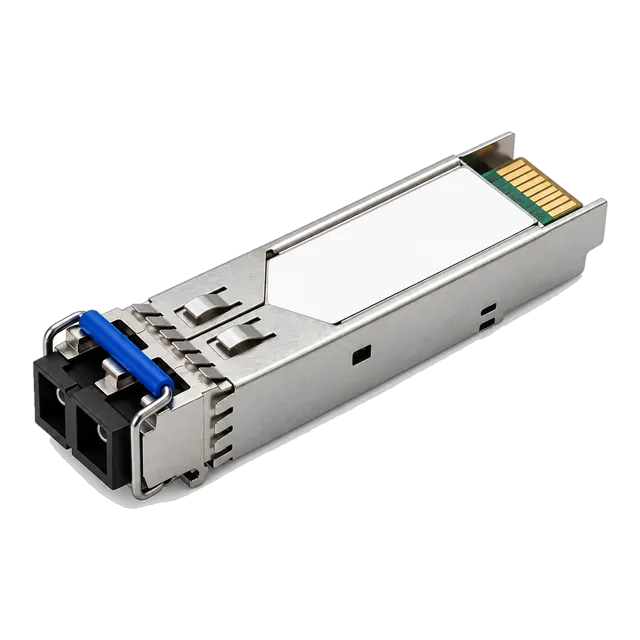
Attenuation in the 1310 nm window sits around 0.32 dB/km to 0.35 dB/km, which is higher than the 1550 nm window but sufficiently low for campus backbones and client-side transceivers. Transceiver standards such as 1000BASE-LX, 10GBASE-LR, and 25GBASE-LR universally leverage 1310 nm optics. Deploying modules such as standard duplex 1.25G SFP 1310nm 10km modules provides an optimal cost-to-performance ratio for enterprise backbones without risking the pulse spreading penalties encountered at other optical bands.
05The 1550 nm low-attenuation window for long-haul transmission
Operating at 1550 nm provides the lowest optical attenuation in silica glass, typically between 0.18 dB/km and 0.22 dB/km, making it mandatory for transport spans exceeding 40 km. At 1550 nm, Rayleigh scattering—which is inversely proportional to the fourth power of the wavelength (1/λ⁴)—is significantly reduced compared to 1310 nm. This enables optical carriers to cover long distances before reaching the receiver sensitivity threshold, reducing the need for intermediate optical regeneration.
The trade-off for minimal attenuation at 1550 nm is elevated chromatic dispersion. In standard ITU-T G.652 singlemode optical fiber, dispersion at 1550 nm reaches approximately 17 ps/(nm·km) to 18 ps/(nm·km). For data rates of 10 Gbps and 25 Gbps, this chromatic dispersion broadens optical pulses quickly, causing bit errors unless narrow-linewidth Electro-Absorption Modulated Lasers (EMLs) or forward error correction (FEC) algorithms are deployed. When planning extended-reach connections, engineers should refer to our detailed optical link budget calculation guide to ensure both attenuation and dispersion limits remain within specification.
06CWDM vs DWDM wavelength allocation grids
Wavelength division multiplexing expands existing single-mode fiber capacity by multiplexing multiple discrete fiber optic wavelengths onto a single physical glass strand. Two primary architectural standards govern this multiplexing: Coarse Wavelength Division Multiplexing (CWDM) and Dense Wavelength Division Multiplexing (DWDM), both defined by the ITU-T.
CWDM is governed by ITU-T G.694.2 and features a wide channel spacing of 20 nm spanning 18 distinct channels from 1270 nm to 1610 nm. Because of the wide channel spacing, uncooled DFB lasers without thermoelectric coolers (TECs) can be used, keeping transceiver design simple and power consumption low. However, full-spectrum CWDM deployment requires ITU-T G.652.D low-water-peak singlemode optical fiber to prevent catastrophic signal absorption in the E-band (1360 nm to 1460 nm).
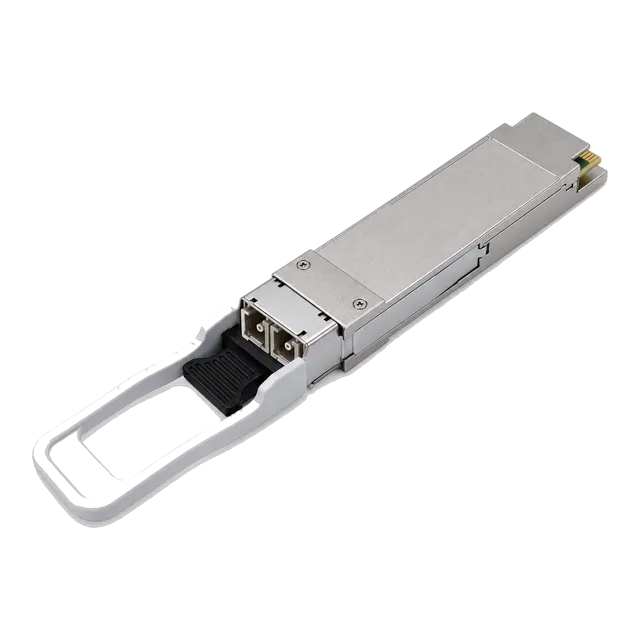
Conversely, DWDM is governed by ITU-T G.694.1 and operates primarily within the low-loss C-band (1528 nm to 1565 nm) and L-band using precise channel grids spaced at 100 GHz (0.8 nm), 50 GHz (0.4 nm), or flexible grid increments. DWDM transceivers demand temperature-stabilised, hermetically sealed EML or external-cavity lasers to maintain exact wavelength stability, but they allow up to 96 high-speed channels over a single fibre pair across hundreds of kilometres using in-line EDFAs. For specialised 100G links without full DWDM complexity, solutions like the 100G QSFP28 eZR4 LWDM4 optical transceiver utilise narrow LAN-WDM channel spacing around 1310 nm to achieve 100 km reach with integrated semiconductor optical amplification.
07Single-fibre BiDi wavelength pairing rules
Bidirectional (BiDi) optical modules double transmission capacity over existing infrastructure by transmitting and receiving simultaneously over a single optical strand using two distinct fiber optic wavelengths. To avoid optical interference and receiver saturation, internal diplexer filters separate the incoming and outgoing light paths inside the small form-factor pluggable transceiver housing.
When provisioning BiDi connections, engineers must adhere strictly to complementary wavelength pairing. An upstream transceiver transmitting at wavelength A must connect directly to a downstream transceiver that receives at wavelength A and transmits at wavelength B. Common commercial pairings include:
- 1310 nm / 1490 nm: Common in passive optical networks (PON) and legacy metro Ethernet access rings up to 40 km.
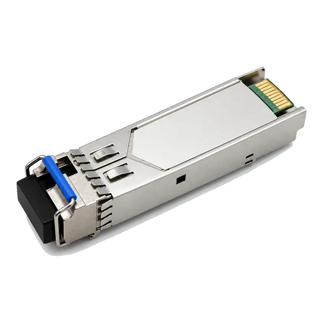
- 1310 nm / 1550 nm: Frequently deployed on standard gigabit links, such as pairing the 1.25G BiDi single-fiber SFP transceiver 1310nm/1550nm 20km with its complementary 1550nm/1310nm partner.
- 1270 nm / 1330 nm: Standardised in IEEE 802.3ae and IEEE 802.3cc for 10G and 25GBASE-BX interfaces across singlemode optical fiber up to 40 km.
Mismatched TX/RX pairs fail to establish link continuity, while plugging matching transceivers (such as 1310 nm TX into another 1310 nm TX) causes complete optical blinding. Consult our practical BiDi modules pairing checklist before finalising system bills of materials.
08Calculating link attenuation and dispersion penalties across wavelengths
Calculating total channel insertion loss and dispersion penalty requires evaluating the specific fiber optic wavelengths against the optical fiber parameters specified in ITU-T G.652.D. The mathematical formula for total channel loss is:
Total Link Loss (dB) = (α_fiber × L) + (N_conn × L_conn) + (N_splice × L_splice) + P_disp + M_safety
Consider a practical engineering comparison across a 40 km link over standard G.652.D singlemode optical fiber equipped with 4 connector pairs (0.5 dB loss each) and 8 fusion splices (0.1 dB loss each), maintaining a 3.0 dB engineering safety margin:
- 1310 nm Transmission Analysis:
Fiber attenuation coefficient (α) = 0.35 dB/km
Fiber loss = 40 km × 0.35 dB/km = 14.0 dB
Connection loss = 4 × 0.5 dB = 2.0 dB
Splice loss = 8 × 0.1 dB = 0.8 dB
Dispersion penalty (P_disp) at zero-dispersion slope ≈ 0.2 dB
Total Channel Loss = 14.0 + 2.0 + 0.8 + 0.2 + 3.0 = 20.0 dB. - 1550 nm Transmission Analysis:
Fiber attenuation coefficient (α) = 0.20 dB/km
Fiber loss = 40 km × 0.20 dB/km = 8.0 dB
Connection loss = 4 × 0.5 dB = 2.0 dB
Splice loss = 8 × 0.1 dB = 0.8 dB
Dispersion penalty (P_disp) for standard DFB laser ≈ 1.0 dB
Total Channel Loss = 8.0 + 2.0 + 0.8 + 1.0 + 3.0 = 14.8 dB.
While 1550 nm saves 5.2 dB of optical link margin on attenuation, its chromatic dispersion must not exceed the transmitter's maximum dispersion tolerance, which is critical when upgrading link rates from 1.25 Gbps to 10 Gbps or 25 Gbps without dispersion compensation.
09Wavelength selection comparison matrix for enterprise and metro links
Matching the optical wavelength to physical plant parameters requires evaluating link distance, optical fiber media, dispersion limits, and equipment budget. The following decision matrix summarises key optical parameters across standard deployment scenarios:
| Wavelength (nm) | Fibre Category | Typical Attenuation (dB/km) | Chromatic Dispersion (ps/(nm·km)) | Practical Max Reach | Primary Application Standard |
|---|---|---|---|---|---|
| 850 | Multimode (OM3 or OM4) | 2.30 to 3.00 | N/A (Modal limited) | 100 m – 300 m | 10GBASE-SR, 25GBASE-SR, 100GBASE-SR4 |
| 1310 | Singlemode (G.652) | 0.32 to 0.35 | ≤ 3.5 | 10 km – 40 km | 1000BASE-LX, 10GBASE-LR, 25GBASE-LR |
| 1490 | Singlemode (G.652) | 0.24 to 0.28 | ≈ 11.0 | 40 km – 80 km | 10GBASE-BX, GPON / XGS-PON Downstream |
| 1550 | Singlemode (G.652) | 0.19 to 0.22 | ≈ 17.5 | 40 km – 120 km | 10GBASE-ER/ZR, 100GBASE-ER4, DWDM C-Band |
| 1625 | Singlemode (G.652) | 0.20 to 0.23 | ≈ 20.0 | Maintenance | OTDR In-Service Link Testing and Monitoring |
For high-capacity campus core links running multiple lanes, comparisons between CWDM, LAN-WDM, and parallel multimode optics are further examined in our analysis of 100G optics: SR4, CWDM4, LR4 and BiDi compared.
10Optical transceiver spectral width and transmitter types
A transceiver's optical spectrum is not a single mathematical line; it possesses an optical spectral width that directly influences chromatic dispersion susceptibility. Different laser diode manufacturing techniques yield distinctly different spectral outputs, determining the achievable reach of specific fiber optic wavelengths.
VCSELs and Fabry-Pérot (FP) lasers exhibit wide spectral distributions comprising multiple longitudinal modes, with root-mean-square (RMS) spectral widths ranging from 0.8 nm to over 3.0 nm. Because different spectral components propagate down the singlemode optical fiber at slightly different group velocities, FP lasers are strictly limited to short-reach connections under 20 km to prevent pulse broadening.
For longer reaches and higher symbol rates, Distributed Feedback (DFB) lasers and Electro-Absorption Modulated Lasers (EMLs) integrate Bragg grating reflectors that restrict emission to a single longitudinal mode. These single-frequency lasers achieve narrow -20 dB spectral widths below 0.1 nm and high side-mode suppression ratios (SMSR) exceeding 30 dB. In DWDM optics, external-cavity lasers and advanced transmission engines narrow this line further to tens of kilohertz, allowing transmission across thousands of kilometres without unrecoverable dispersion distortion.
11How to specify fiber optic wavelengths in procurement documents
To prevent costly delivery errors and physical layer incompatibilities, procurement engineers must clearly define optical wavelength parameters in Requests for Quotation (RFQs) and equipment specifications. Vague requests for "single-mode optics" frequently result in transceivers with incompatible optical reaches, missing laser types, or unworkable BiDi pairings.
Ensure your optical module RFQs include the following technical specifications:
- Nominal Center Wavelength and Spectral Tolerance: Explicitly state both the operating centre wavelength (e.g., 1310 nm ± 20 nm for O-Band, or exact ITU-T 100 GHz grid frequency for DWDM).
- Optical Fibre Class: Clarify whether the target plant is ISO/IEC 11801 OM3 or OM4 multimode or ITU-T G.652.D / G.657.A1 singlemode optical fiber to verify attenuation and dispersion compliance.
- Transmitter Technology: Specify laser category (VCSEL, FP, DFB, or cooled EML) and require minimum side-mode suppression ratios (SMSR ≥ 30 dB) for long-span applications.
- Single-Fibre Pairing Designations: When ordering BiDi transceivers, procure TX/RX matched complementary pairs in equal quantities (e.g., matching 1310 nm TX / 1550 nm RX with 1550 nm TX / 1310 nm RX).
- Diagnostic and Monitoring Support: Mandate digital diagnostic monitoring (DDM / DOM) compliant with SFF-8472 to verify live operating wavelength power levels, laser bias currents, and internal module temperatures.
Review our structured guide on how to choose the right optical transceiver for your network to audit your equipment bills of materials prior to final procurement sign-off.
12Frequently asked questions
What are the most common fiber optic wavelengths?
The three most common fiber optic wavelengths are 850 nm, 1310 nm, and 1550 nm. The 850 nm wavelength is used for multimode data centre links, 1310 nm balances zero chromatic dispersion for campus and metro single-mode links up to 40 km, and 1550 nm provides the lowest attenuation for long-haul and DWDM connections.
Why is 1310 nm preferred over 1550 nm for shorter single-mode links?
1310 nm is preferred for links up to 40 km because standard G.652 singlemode optical fiber exhibits near-zero chromatic dispersion in this band. This allows manufacturers to use lower-cost, uncooled Fabry-Pérot and DFB lasers without needing dispersion compensation circuitry or complex modulation schemes.
Can you run 1310 nm optics over multimode fiber?
Yes, 1310 nm optics can operate over multimode fiber using standard 1000BASE-LX or 10GBASE-LRM interfaces, but they typically require a mode-conditioning patch cable. The mode-conditioning cable launches the single-mode laser beam off-centre into the multimode core to prevent differential mode delay (DMD) distortions.
What is the water peak in optical fiber transmission?
The water peak is an attenuation spike around 1383 nm in the E-Band, caused by trace hydroxyl ion (OH-) impurities absorbed during glass manufacturing. Modern ITU-T G.652.D low-water-peak singlemode optical fiber eliminates this impurity, enabling seamless CWDM transmission across the entire 1270 nm to 1610 nm range.
Why do BiDi transceivers require two different wavelengths?
BiDi transceivers require two different wavelengths so that transmitting and receiving signals can travel simultaneously over a single strand of glass without interfering. Internal optical diplexers separate the two wavelengths, preventing transmit back-reflection from saturating the sensitive local optical receiver.
How does chromatic dispersion vary with wavelength?
In standard G.652 singlemode optical fiber, chromatic dispersion is near zero at 1312 nm and increases progressively up to roughly 17 ps/(nm·km) at 1550 nm. Consequently, 1550 nm links experience greater pulse broadening per kilometre, requiring narrow-linewidth lasers or forward error correction at high bitrates.
Technical review note: confirm model-specific specifications with the product datasheet and the intended host documentation. Product images and application photographs are illustrative.
Discuss this with our team