100GBASE-SR4 gives you a tight loss budget and eight fibers in one MPO-12, so polarity, connector gender and end-face cleanliness decide whether the link works.
01What 100GBASE-SR4 actually is
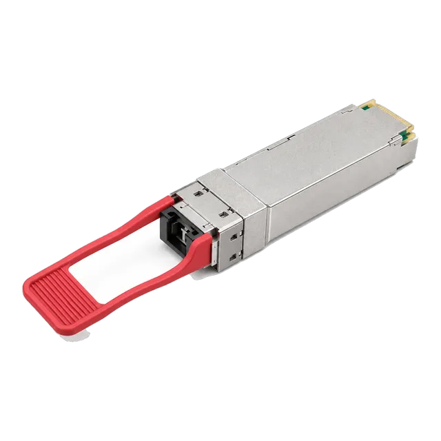
100GBASE-SR4 carries 100 Gb/s as four parallel lanes of 25 Gb/s, each on its own fiber in each direction, using 850 nm VCSEL sources over multimode fiber. The module presents an MPO-12 or MTP-12 receptacle in a QSFP28 form factor, and eight of the twelve fiber positions are used, four transmitting and four receiving, with the middle four unused in the standard arrangement. Our catalog lists several items in this class, including the 100G QSFP28-SR4 100Gb/s 850nm MPO-12 Multimode Fiber Optic and the 100G QSFP28 SR4 DDM Data Center Optical Transceiver Module. Because the link is parallel rather than multiplexed, it depends on a cabling system that keeps twelve fibers in the correct order end to end, which is the main difference from the duplex links most engineers are used to planning.
02Reach on OM3, OM4 and OM5
IEEE 802.3 specifies 100GBASE-SR4 at up to 70 metres over OM3 and up to 100 metres over OM4, under the channel loss and modal bandwidth the standard assumes. OM5 behaves like OM4 for this application, since SR4 uses a single wavelength and gains nothing from wideband performance. Catalog entries frequently quote 100 metres, as ours do; treat that as the OM4 case and confirm the OM3 figure against the model datasheet before designing to it. Legacy OM1 and OM2 fiber is not a candidate at this rate. If the route exceeds what the fiber grade supports, the answer is not a longer patch cord but a different module class: a single-mode approach such as 100GBASE-CWDM4 at 2 kilometres, or PSM4 where parallel single-mode cabling already exists.
03The loss budget is unusually tight
Short-reach parallel optics are designed around very little link loss. The total channel insertion loss allowed for an SR4 link is under two decibels, which is small compared with the four to six decibels a single-mode link at the same speed can absorb. At 850 nm multimode fiber contributes roughly three decibels per kilometre, so over one hundred metres the fiber itself accounts for only a fraction of a decibel and almost the entire budget is consumed by connections. Each mated MPO pair can cost anywhere from a few tenths of a decibel to three quarters of a decibel depending on quality and cleanliness. Count the mated pairs in your intended route, multiply by a realistic per-connection figure rather than an optimistic one, and confirm the resulting number against the channel loss figure on the model datasheet.
04Count connections, not metres
A structured cabling route rarely consists of a single cable. A typical data centre path runs from the switch, through a patch cord, into a cassette or adapter panel, along a trunk, into a second cassette, and out through a second patch cord. That is four mated pairs before the light reaches the far module, and each one spends part of a budget that is under two decibels in total. This is why SR4 links that work on a bench fail in a cabling system, and why adding one more panel to an existing route can break a link that was previously stable. Where the design needs more connections than the budget tolerates, use a direct trunk between the two switches, or move the link to a single-mode module class with more headroom.
05MPO polarity methods A, B and C
Polarity is the discipline that ensures each transmit fiber lands on a receive fiber at the far end. The cabling standards describe three methods. Method A uses straight-through trunks with a key-up to key-down adapter, and requires a crossover somewhere, usually in one of the patch cords. Method B uses a trunk in which position one maps to position twelve, with key-up to key-up adapters. Method C pairs adjacent fibers in a flipped arrangement and is intended for duplex applications rather than parallel ones. For parallel optics such as SR4, the practical requirement is that the full array is reversed exactly once across the channel. Choose one method for the site, apply it consistently, and record it in the cabling documentation, because mixing methods produces links that fail in ways that look like hardware faults.
06Pinned and unpinned connectors
MPO connectors exist in pinned and unpinned forms, and a mated pair must consist of exactly one of each; the pins align the two ferrules so the fiber cores meet. Two unpinned connectors will mate physically but not align properly, and two pinned connectors cannot be mated at all without damage. The gender of the module receptacle determines what the patch cord must be, so confirm it from the model datasheet rather than assuming, and confirm the gender of every trunk and cassette port in the route as well. Draw the channel as a diagram showing the gender at each interface before ordering cabling. This takes a few minutes and prevents a delivery of patch cords that cannot be used, which is a common and entirely avoidable cause of delay.
07Forward error correction is part of the link
Ethernet at 25 Gb/s per lane relies on Reed-Solomon forward error correction to reach its specified bit error ratio, and for 100GBASE-SR4 the RS-FEC layer is part of the standard rather than an option. In practice this means both host ports must have the expected FEC mode configured and they must agree. A mismatch commonly presents as a link that will not come up, or one that comes up and then accumulates errors. Include a FEC check in commissioning: confirm the mode configured at each end, then read the corrected and uncorrected codeword counters after a soak period. A link showing steadily rising uncorrected codewords has a physical problem even if optical power looks acceptable, and the usual causes are connector loss, contamination or a route beyond the fiber's capability.
08Cleaning and inspecting MPO end faces
An MPO ferrule presents twelve fiber cores on one face, so a single particle can affect one lane out of four and produce a link that is up but erroring in a way that is hard to attribute. Multimode cores are larger than single-mode cores, which helps a little, but the number of interfaces in a parallel channel more than cancels that advantage. Inspect every MPO end face with a scope designed for multi-fiber connectors before mating, clean with a cassette or stick cleaner intended for MPO, and inspect again. Cap every connector the moment it is unmated. Treat cleaning as a required step in the installation method statement rather than as a remedy applied after a link fails, because cleaning after contamination has been mated can transfer debris to the adapter.
09Breakout to four 25G links
Many platforms allow a QSFP28 port to be operated as four independent 25 Gb/s lanes, connected through an MPO-to-four-duplex-LC harness to four 25GBASE-SR modules such as the 25GBASE-SR SFP28 850nm 100m VCSEL Multimode Duplex LC in our catalog. This is attractive for server attachment, but it is entirely a host capability: the platform must support breakout on that specific port, the port numbering changes, adjacent ports in the same group are often affected, and a reload may be required. The optical side must also line up, since 25GBASE-SR is specified to 70 metres on OM3 and 100 metres on OM4, and the harness adds its own connections to the budget. Confirm the platform's breakout support and the resulting configuration before ordering the harness.
10Airflow, density and power at the faceplate
A fully populated QSFP28 faceplate concentrates a significant amount of heat in a small area, and the modules that suffer first are usually those in the middle of a dense row where airflow is most obstructed. Our SR4 items are listed with a 0 to 70 degrees Celsius operating range, and the relevant figure is the air entering the cage rather than the room temperature. Check the module case temperature through DDM once the chassis is populated as it will be in service, not during a half-filled pilot. Make sure the chassis airflow direction matches the aisle containment, that blanking panels are fitted, and that thick MPO trunk bundles are dressed away from the intake. Thermal problems on parallel optics often appear as intermittent lane errors rather than as clean failures.
11Commissioning and acceptance
Accept the channel before accepting the link. Ask the cabling contractor for an insertion loss test of each MPO channel at 850 nm, performed with a reference method appropriate to multi-fiber connectors, and compare the result with your budget rather than only with the contractor's own pass threshold. Then bring the link up and record DDM values at both ends, including per-lane receive power where the platform exposes it, since a single weak lane is the characteristic signature of a polarity or cleanliness problem in a parallel channel. Run traffic for an agreed soak period and check interface and FEC counters. Store the channel test, the DDM baseline and the polarity method used with the link documentation.
12What to specify when ordering
State the standards designation, 100GBASE-SR4, rather than a generic description, together with the form factor, the connector as MPO-12 or MTP-12, the fiber grade the link will run on, the route length, the number of mated connections in the channel, the temperature grade, the DDM requirement, the host platform and software version at each end for coding, and the quantity with spares. Say whether breakout operation is intended, since that affects the cabling and possibly the module choice. Ask for the datasheet of the exact model quoted, including its channel insertion loss allowance and its stated reach on both OM3 and OM4, and treat catalog reach figures as needing confirmation per model before the design is fixed.
13Frequently asked questions
How far can 100GBASE-SR4 run on OM3 and OM4?
IEEE 802.3 specifies up to 70 metres over OM3 and up to 100 metres over OM4, assuming the channel stays within the standard's loss and modal bandwidth limits. OM5 offers no advantage here because SR4 uses a single wavelength. Catalog listings that quote 100 metres describe the OM4 case; confirm both figures against the datasheet of the exact model you intend to order.
What connector does a 100G SR4 transceiver use?
An MPO-12 or MTP-12 multi-fiber receptacle. Eight of the twelve positions carry traffic, four transmitting and four receiving, with the middle four unused in the standard arrangement. The receptacle gender determines whether the patch cord must be pinned or unpinned, so confirm it on the datasheet before ordering cabling, since a mated pair needs exactly one pinned and one unpinned connector.
Which MPO polarity method should I use for SR4?
Any method that reverses the fiber array exactly once across the whole channel will work; method B is widely used for parallel optics because the trunk itself provides the reversal. What matters more than the choice is consistency: pick one method for the site, apply it to every trunk, cassette and patch cord, and record it in the cabling documentation so later additions match.
Why does my 100G SR4 link fail in a patch panel system but work back to back?
Almost certainly the loss budget. SR4 allows under two decibels of total channel insertion loss, and each mated MPO pair can consume a large share of that. A structured route with patch cords, cassettes and a trunk easily contains four mated pairs. Count the connections, use realistic per-connection loss, inspect and clean every end face, or use a direct trunk instead.
Can I break out a 100G SR4 port into four 25G links?
Only where the host platform supports breakout on that specific port. The platform must allow the port to run as four lanes, the port numbering changes, adjacent ports in the group are often affected and a reload may be needed. On the optical side you need an MPO-to-four-duplex-LC harness and 25GBASE-SR modules at the far ends, within their own reach limits.
Technical review note: confirm model-specific specifications with the product datasheet and the intended host documentation. Product images and application photographs are illustrative.
Discuss this with our team