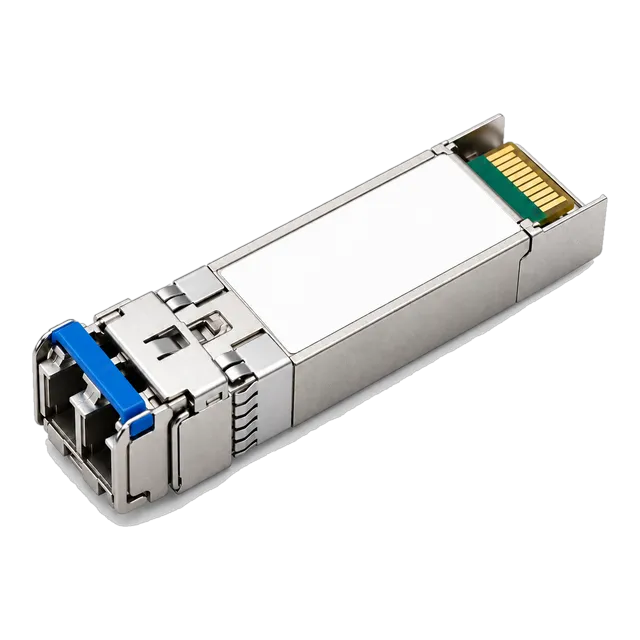
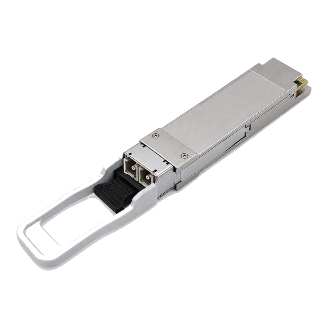
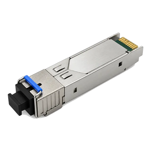
Selecting the right OFC connector type requires aligning ferrule geometry (1.25 mm vs 2.5 mm), polish angle (UPC vs APC), and housing form factor with your transceiver optics and insertion loss budget according to IEC 61753 standards.
01What is an OFC connector type and how does it function?
An optical fiber cable (OFC) connector type defines the mechanical housing, ferrule diameter, latching mechanism, and end-face polish that terminates an optical fiber core. In optical communications, every ofc connector type provides non-permanent jointing between optical patch leads, distribution panels, and pluggable transceiver ports. The fundamental mechanism relies on precise physical alignment of two hair-thin glass cores—typically 9 µm for single-mode fiber (SMF) or 50 µm for multimode fiber (MMF)—within a ceramic zirconia ferrule. By aligning the cores along three axes (lateral, angular, and longitudinal), optical fiber termination types minimise optical insertion loss (IL) and suppress optical return loss (ORL). Industrial deployments standardise on these connector interfaces to allow quick reconfiguration of rack-mounted hardware without requiring permanent fusion splicing.
02OFC connector type comparison chart
Optical connector types differ substantially in ferrule dimensions, mechanical latching, density profile, and standard network applications. The following fiber optic connector chart provides performance benchmarks governed by IEC 61754 and TIA-604 interface standards.
| OFC Connector Type | Ferrule Diameter (mm) | Standard Polish Grades | Typical Insertion Loss (dB) | Minimum Return Loss (dB) | Common Optical Transceiver Formats |
|---|---|---|---|---|---|
| LC (Lucent Connector) | 1.25 | UPC, APC | 0.15 to 0.25 | ≥ 50 (UPC), ≥ 60 (APC) | SFP, SFP+, SFP28, QSFP28 Duplex |
| SC (Subscriber Connector) | 2.50 | UPC, APC | 0.20 to 0.30 | ≥ 50 (UPC), ≥ 60 (APC) | Legacy SFP BiDi, Media Converters, PON ONT |
| ST (Straight Tip) | 2.50 | PC, UPC | 0.25 to 0.40 | ≥ 40 (PC), ≥ 50 (UPC) | Industrial Ethernet, Legacy Campus MMF |
| FC (Ferrule Connector) | 2.50 | PC, UPC, APC | 0.20 to 0.30 | ≥ 50 (UPC), ≥ 65 (APC) | Test Equipment, Telecom OTDR, High-Vibration |
| MPO / MTP (Multi-Fiber) | Array (12/16/24) | PC (MMF), APC (SMF) | 0.35 to 0.70 | ≥ 20 (PC), ≥ 60 (APC) | QSFP+, QSFP28 parallel optics, OSFP, QSFP-DD |
| CS Connector | 2 x 1.25 (Dual) | UPC, APC | 0.15 to 0.20 | ≥ 50 (UPC), ≥ 60 (APC) | QSFP-DD, OSFP 200G/400G Breakouts |
| SN / MDC | 2 x 1.25 (Micro) | UPC, APC | 0.15 to 0.20 | ≥ 50 (UPC), ≥ 60 (APC) | High-Density 400G/800G Transceiver Breakout |
This fiber connector types chart illustrates why small form-factor plugs have superseded legacy 2.5 mm interfaces across enterprise data centres and carrier transmission networks.
03LC connectors: the modern optical transceiver standard
The LC (Lucent Connector) is the predominant optical connector used across modern telecommunications and data centre networks. Standardised under IEC 61754-20, the LC interface features a miniaturised 1.25 mm zirconia ceramic ferrule and an RJ45-style push-pull latching clip that prevents accidental disconnects under tension. Because it halves the footprint of older 2.5 mm interfaces, LC enables high-density line cards and switches. Duplex LC configurations are the default optical interface for standard modules such as the 25G SFP28 ZR 1310nm 80km Single-Mode Duplex LC Long-Reach transceiver and long-reach 100G optics such as the 100G QSFP28 eZR4 100km LWDM4 Duplex LC SMF Optical module. For detailed architectural guidelines on small form-factor interfaces, review our SFP LC Connector Guide.
04SC and legacy fiber connector types in carrier networks
SC (Subscriber Connector), ST (Straight Tip), and FC (Ferrule Connector) represent the traditional 2.5 mm ferrule family of fiber optic connectors. The SC interface (IEC 61754-4) utilises a push-pull square plastic housing that provides audible feedback upon full engagement. SC connectors remain standard across Gigabit Passive Optical Networks (GPON), fiber-to-the-home (FTTH) distribution boxes, and industrial equipment such as the 1.25G SFP BiDi Optical Module 20km 1310nm/1550nm SC transceiver. ST connectors (IEC 61754-2) feature a spring-loaded bayonet twist-lock barrel, commonly encountered in legacy multi-mode building automation backbones. FC connectors (IEC 61754-13) rely on a threaded metallic barrel designed to prevent disconnects and optical misalignments in high-vibration railway, maritime, and lab test instrumentation.
05MPO and MTP multi-fiber connectors for high-density links
MPO (Multi-Fiber Push-On) connectors terminate multiple optical cores—typically 8, 12, 16, or 24 fibers—in a single rectangular polymer ferrule. Standardised under IEC 61754-7 and TIA-604-5, MPO connectors support parallel optical transmission across multi-lane transceivers like 40GBASE-SR4, 100GBASE-SR4, and 400GBASE-DR4. MTP is an engineered high-performance variant that incorporates floating ferrules, elliptical stainless-steel guide pins, and removable housings to optimise mechanical alignment and reduce insertion loss below 0.35 dB per interface. Network engineers must pay meticulous attention to optical polarity (Method A, Method B, or Method C) and gender (pinned male versus unpinned female) when patching MPO lines. Detailed design criteria for multi-fiber trunks are documented in our MPO/MTP Polarity and Base-8 Guide.
06Next-generation optical fiber termination types: CS, SN and MDC
Next-generation very small form factor (VSFF) connectors provide double or quadruple the patching density of standard duplex LC interfaces. Standardised by the CS Consortium (TIA-604-19) and the SN/MDC developers, these fiber connection types maintain standard 1.25 mm ferrules while drastically reducing the pitch between fiber pairs. The CS connector reduces ferrule pitch to 3.8 mm (compared to 6.25 mm for duplex LC), allowing two duplex pairs inside a single QSFP-DD or OSFP transceiver port. The SN and MDC connectors compress ferrule spacing down to 3.1 mm, packing four individual duplex connections into a single transceiver cage. This architecture allows native 4x100G breakout connections directly at the switch faceplate without deploying bulky external MPO breakout cassettes.
07Optical fiber end types: PC, UPC and APC polishes explained
Fiber end types dictate how ferrule tip geometries physically mate to control optical reflectance back toward laser transmitters. Physical Contact (PC), Ultra Physical Contact (UPC), and Angled Physical Contact (APC) represent three distinct mechanical polishes defined by IEC 61753-1:
- PC (Physical Contact): Features a curved spherical dome polish producing an optical return loss around -35 dB to -40 dB. Commonly restricted to legacy multimode links.
- UPC (Ultra Physical Contact): Extended mechanical polishing creates a smoother spherical profile with an optical return loss of ≥ -50 dB for single-mode systems. Standard for digital telecommunications, enterprise switches, and Ethernet SFP/SFP28 modules. Identified by blue connector housings.
- APC (Angled Physical Contact): The ferrule end-face is ground to an exact 8-degree angle, redirecting reflected light into the fiber cladding rather than back to the source. Delivers ORL of ≥ -60 dB to -65 dB. Standard for CATV, DWDM, and PON networks. Identified by green connector housings.
Never mate a green APC connector to a blue UPC connector. The 8-degree air gap creates severe insertion loss exceeding 4 dB and permanently destroys the ceramic ferrule cores upon mechanical compression.
08Insertion loss and return loss calculation for fiber connection types
A reliable optical link budget calculation accounts for the cumulative insertion loss across every fiber optic plug, mated pair, and cable segment. According to TIA-568.3-D, the standard attenuation limit for a field-mated single-mode connector pair is 0.75 dB, though premium factory-terminated LC pairs typically operate below 0.20 dB.
Consider an enterprise link calculation for an 8 km single-mode fiber run running 10GBASE-LR at 1310 nm:
- Fiber attenuation: 8.0 km × 0.35 dB/km = 2.80 dB (ITU-T G.652.D fiber)
- Patch panel terminations: 4 mated LC/UPC pairs × 0.25 dB = 1.00 dB
- Fusion splices: 2 intermediate splices × 0.05 dB = 0.10 dB
- Total link insertion loss: 2.80 dB + 1.00 dB + 0.10 dB = 3.90 dB
With an optical transceiver transmitter delivering -3.0 dBm and receiver sensitivity rated at -14.4 dBm, the total available channel budget is 11.4 dB. Subtracting the 3.90 dB calculated insertion loss leaves a robust optical safety margin of 7.50 dB. Engineering procedures for verifying these metrics are explained in our guide on Optical Link Budget Calculations.
09Matching fiber optic cable connector types to transceiver form factors
Correctly pairing fiber optic cable ends with optical transceivers requires matching wavelength, core mode, and connector receptacle geometry. Optical transceivers do not use uniform optical receptacles; their internal optical sub-assemblies (TOSA and ROSA) dictate the physical interface:
- SFP / SFP+ / SFP28: Standard duplex LC/UPC for dual-fiber transceivers; simplex LC/UPC or simplex SC/UPC for single-strand BiDi optical modules.
- QSFP+ / QSFP28 (Duplex): Duplex LC/UPC for CWDM4, LR4, and ER4 single-mode modules using internal wavelength division multiplexing.
- QSFP+ / QSFP28 (Parallel): MPO-12/UPC (multimode SR4) or MPO-12/APC (single-mode PSM4) multi-fiber interfaces.
- Media Converters: Duplex SC or ST for industrial edge media converters; modular SFP slots for enterprise chassis switches.
For in-depth analysis of single-mode transceiver termination rules, refer to our Single Mode Fiber LC Connector Guide.
10Cleaning and inspection standards for fiber optic cable ends
Dirty connector end-faces cause more than 80 percent of premature link failures and optical transceiver damage in production environments. Microscopic dust particles, finger oils, and mineral residue obstruct the optical core, causing localised optical back-reflection and signal attenuation. Under IEC 61300-3-35, inspection criteria define allowable contamination across four concentric zones: Zone A (Core: 0–25 µm), Zone B (Cladding: 25–120 µm), Zone C (Adhesive: 120–130 µm), and Zone D (Contact: 130–250 µm). In single-mode fiber, zero defects or scratches are permitted in Zone A.
- Inspect every connector plug and transceiver bulkhead with a video inspection probe before mating.
- If debris is observed, clean using a dry mechanical click-pen tool matched to the ferrule diameter (1.25 mm for LC/CS, 2.5 mm for SC/FC/ST).
- For stubborn chemical or oil contamination, execute wet-to-dry cleaning using optical-grade solvent (such as high-purity isopropyl alcohol) followed immediately by an optical lint-free wipe.
- Re-inspect the ferrule surface using the probe to confirm zero residual debris prior to inserting the plug into the transceiver optical bore.
11Procurement checklist for optical fiber termination types
Before submitting a request for quotation (RFQ) for optical patch leads, trunk cables, or transceiver optics, ensure the following parameters are explicitly specified to eliminate procurement errors:
- OFC connector type: Specify both ends explicitly (e.g., Duplex LC to Duplex LC, or MPO-12 Female to 4x Duplex LC).
- Ferrule end-face polish: Define UPC (blue) or APC (green) per connector. Never allow ambiguous physical contact specifications on single-mode links.
- Fiber glass specification: State exact ITU-T or ISO standard (e.g., OS2 single-mode ITU-T G.652.D / G.657.A1, or laser-optimised 50/125 µm multimode).
- Cable construction and jacket rating: Require LSZH (Low Smoke Zero Halogen) for European deployments, or OFNP (Plenum) / OFNR (Riser) for North American building codes.
- Maximum Insertion Loss guarantees: Specify grade B (≤ 0.12 dB mean, ≤ 0.25 dB max) or standard grade C (≤ 0.25 dB mean, ≤ 0.50 dB max) per IEC 61753-1.
- Polarity and pinout (for MPO/MTP): Indicate Base-8, Base-12, or Base-24, wiring polarity (Method A, B, or C), and guide pin configuration (male pinned for patch panels, female unpinned for transceivers).
12Frequently asked questions
What is the difference between an LC and SC fiber connector?
LC connectors utilise a compact 1.25 mm ceramic ferrule with an RJ45-style latch, making them ideal for high-density transceivers. SC connectors use a larger 2.5 mm ferrule with a push-pull shell, commonly found in legacy carrier equipment, FTTH subscriber terminals, and media converters.
Can you connect an APC fiber connector to a UPC connector?
No, you must never mate an APC connector to a UPC connector. The 8-degree angled polish of APC creates a physical gap when pressed against a flat UPC ferrule, resulting in severe insertion loss (often exceeding 4 dB) and potential physical damage to both fiber cores.
Which OFC connector type is used for 100G transceivers?
100G transceivers generally use either duplex LC or MPO-12 connectors. Duplex LC is standard for single-mode transceivers using optical multiplexing (such as 100GBASE-LR4 and CWDM4), while MPO-12 connectors are standard for multi-fiber parallel optics like 100GBASE-SR4 and PSM4.
What causes high insertion loss in fiber optic connectors?
High insertion loss is primarily caused by microscopic dust and oils on the ferrule end-face, misaligned fiber cores, air gaps from improper mating, or end-face damage like scratches and pitting. Contamination accounts for the vast majority of optical network attenuation issues.
What is the difference between single-mode and multimode fiber connectors?
Single-mode connectors require tighter mechanical tolerances to align a 9 µm core and typically use UPC (blue) or APC (green) polishes. Multimode connectors align wider 50 µm or 62.5 µm cores, utilise PC or UPC flat polishes, and usually feature beige, aqua, or magenta housings.
Technical review note: confirm model-specific specifications with the product datasheet and the intended host documentation. Product images and application photographs are illustrative.
Discuss this with our team