Wavelength division multiplexing multiplies single-fibre capacity by combining distinct optical wavelengths onto discrete channels, allowing network operators to scale from 1.25 Gbps access rings to 100 Gbps routed backbones without leasing or trenching new civil infrastructure.
01What does WDM mean in optical networking?
Wavelength division multiplexing is an optical communications technique that transmits multiple discrete data streams simultaneously over a single strand of optical fibre by assigning each data stream to a unique wavelength of light. Instead of dedicating an entire optical fibre pair to a single optical transceiver, wavelength division multiplexing (WDM) combines several laser carrier signals onto a shared physical medium. At the receiving end, an optical demultiplexer separates the composite optical signal into its constituent wavelengths and directs each channel to its designated optical receiver.
Understanding what WDM means requires viewing optical fibre as an ultra-wideband transmission highway. Standard single-mode fibre conforming to ITU-T G.652.D provides an optical transmission spectrum spanning from roughly 1260 nm to 1625 nm, offering tens of terahertz of usable optical bandwidth. Traditional point-to-point links utilise only a fraction of this spectrum—typically a single 1310 nm or 1550 nm channel. By implementing wavelength multiplexing, operators convert a single strand of glass into dozens of parallel, non-interfering logical channels. Each channel can operate at independent data rates, such as 1.25 Gbps, 10 Gbps, 25 Gbps, or 100 Gbps, and use completely different transmission protocols, including Gigabit Ethernet, Fibre Channel, or Synchronous Optical Networking (SONET/SDH).
02Wavelength division multiplexing
Wavelength division multiplexing operates on the fundamental physical principle of optical superposition, where electromagnetic waves of different frequencies propagate through a dielectric medium without destructive cross-interference. The foundational components of any WDM architecture include optical transmitters, optical multiplexers (MUX), transmission fibres, optical demultiplexers (DEMUX), and receivers. Transmitters use semiconductor lasers, such as distributed feedback (DFB) or external cavity lasers (ECL), engineered to emit phase-aligned light at strictly controlled centre wavelengths.
In a standard WDM system, the optical multiplexer aggregates these distinct carrier frequencies. Multiplexing technologies rely on passive optical interference filters, such as thin-film filters (TFF), or diffraction-based components, including arrayed waveguide gratings (AWG) and fibre Bragg gratings (FBG). A TFF consists of alternating thin dielectric layers with contrasting refractive indices deposited on a glass substrate, creating cavity resonators that transmit an ultra-narrow optical band while reflecting all adjacent wavelengths. At the receiver side, a complementary demultiplexer isolates each optical carrier with high adjacent-channel isolation (typically greater than 30 dB) to prevent inter-channel crosstalk before presenting the signal to a PIN photodiode or avalanche photodiode (APD). When designing multi-span routes, engineers consult our guide to fibre optic wavelengths and transmission windows to evaluate chromatic dispersion and attenuation profiles across specific spectral bands.
03WDM CWDM DWDM: Understanding the three core topologies
The optical networking industry divides wavelength division multiplexing into three distinct standard architectures: broad wavelength division multiplexing (BWDM/BiDi), coarse wavelength division multiplexing (CWDM), and dense wavelength division multiplexing (DWDM). The technical differentiation between these architectures centres on channel spacing, spectral band utilisation, laser temperature stabilization requirements, and maximum transmission reach.
Broad WDM commonly describes bidirectional (BiDi) transmission over a single optical strand, typically combining two widely separated nominal wavelengths such as 1310 nm and 1490 nm, or 1310 nm and 1550 nm. CWDM broadens the channel count across a wide spectral range, using uncooled lasers with wide 20 nm channel spacing according to ITU-T G.694.2. In contrast, DWDM condenses optical channels into the low-attenuation C-band (1530 nm to 1565 nm) and L-band (1565 nm to 1625 nm), utilizing tight channel spacings of 100 GHz (0.8 nm), 50 GHz (0.4 nm), or even 25 GHz (0.2 nm) per ITU-T G.694.1. Selecting between CWDM and DWDM requires balancing equipment cost against total system capacity, optical amplification requirements, and distance.
04Coarse wavelength division multiplexing: Channels, grid, and deployment
Coarse wavelength division multiplexing defines an optical transmission grid of up to 18 discrete channels spaced 20 nm apart, ranging from 1270 nm to 1610 nm as standardised in ITU-T G.694.2. Because the channel spacing is substantial, CWDM transceivers can use uncooled DFB lasers that drift with ambient operational temperatures. An uncooled laser exhibits a temperature-induced spectral drift of approximately 0.1 nm/°C. Over a standard commercial operating range of 0 °C to 70 °C, the laser centre wavelength may drift by up to 7 nm. The 20 nm channel passband comfortably accommodates this thermal wander without dropping signal outside the passband of the optical filter, eliminating the requirement for power-hungry thermoelectric coolers (TEC).
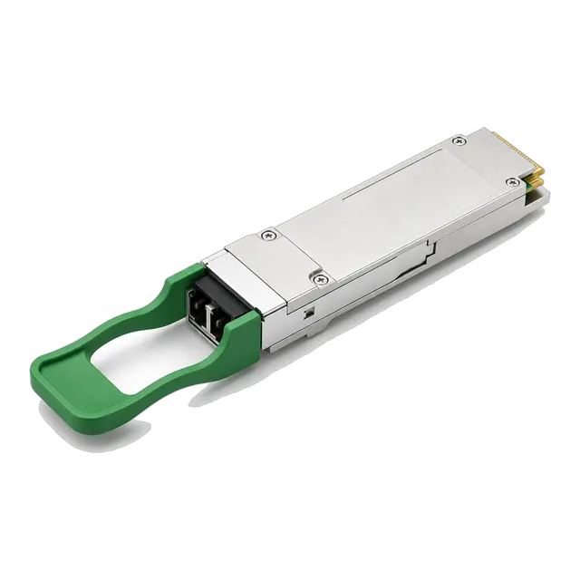
Despite supporting 18 theoretical channels, practical CWDM deployments on legacy G.652.A and G.652.B single-mode fibre are typically restricted to eight channels between 1470 nm and 1610 nm. This restriction occurs because legacy fibres feature a severe optical attenuation peak—termed the water peak—around 1383 nm, caused by residual hydroxyl (OH-) ion contamination introduced during glass manufacturing. On modern low-water-peak fibres conforming to ITU-T G.652.D or bend-insensitive ITU-T G.657.A1, the water peak is eliminated, enabling full 18-channel CWDM operation across the E-band (1360 nm to 1460 nm). In high-density campus interconnects, quad-lane pluggables such as the 100G QSFP28 CWDM4 optical transceiver integrate internal four-channel CWDM multiplexers directly into the optical sub-assembly to provide 100 Gbps bandwidth over standard duplex LC single-mode fibre spans up to 2 km.
05Dense wavelength division multiplexing: ITU-T grid and channel plans
Dense wavelength division multiplexing provides high-density optical transmission by compressing dozens of optical channels into very narrow frequency intervals defined by the ITU-T G.694.1 frequency grid. The reference anchor frequency for this grid is fixed at 193.10 THz (approximately 1552.52 nm). Channels are allocated on nominal frequency spacings of 100 GHz (0.8 nm), 50 GHz (0.4 nm), 25 GHz (0.2 nm), or flexible grid intervals in increments of 12.5 GHz for high-baud-rate transponders.
Because the physical channel spacing in dense wavelength division multiplexing is microscopic compared to CWDM, an uncooled laser would drift across multiple adjacent channels within seconds of thermal fluctuation. Consequently, DWDM transceivers incorporate hermetically sealed DFB lasers or tunable external cavity lasers paired with an integrated TEC and internal wavelength lockers. The wavelength locker uses a Fabry-Pérot etalon to continuously monitor the laser emission frequency and adjust the TEC injection current, locking the centre wavelength to within ±0.02 nm of the ITU grid slot across all ambient temperature conditions. DWDM primarily targets the optical C-band (Conventional Band: 1530 nm to 1565 nm) and L-band (Long Wavelength Band: 1565 nm to 1625 nm). These bands exhibit the lowest intrinsic attenuation on silica fibre—roughly 0.18 to 0.22 dB/km—and coincide precisely with the operating gain window of optical amplifiers.
06Technical comparison: CWDM vs DWDM vs LWDM specifications
Evaluating optical multiplexing options requires comparing physical parameters, channel capacities, amplification constraints, and component thermal tolerances across standardized architectures. The table below outlines key engineering criteria across BiDi, CWDM, DWDM, and LAN-WDM (LWDM) architectures.
| Specification Metric | BiDi WDM | CWDM (ITU-T G.694.2) | DWDM 100 GHz (G.694.1) | DWDM 50 GHz (G.694.1) | LWDM (IEEE 802.3ba) |
|---|---|---|---|---|---|
| Channel Spacing | Wide (>50 nm) | 20 nm | 100 GHz (~0.8 nm) | 50 GHz (~0.4 nm) | 800 GHz (~4.5 nm) |
| Maximum Channels | 2 (per fibre) | 18 (8 typical) | 40 to 48 | 80 to 96 | 4 to 12 |
| Spectral Operating Bands | O, S, C, or L bands | 1270 nm to 1610 nm | C-band / L-band | C-band / L-band | 1269 nm to 1332 nm (O-band) |
| Laser Cooling (TEC) | Uncooled | Uncooled | TEC Required | TEC Required | TEC Required |
| Wavelength Locking | Not required | Not required | Required (±0.02 nm) | Required (±0.01 nm) | Required |
| Optical Amplification | Not applicable | Cost-prohibitive | EDFA / Raman viable | EDFA / Raman viable | SOA viable |
| Typical Transceiver Reach | Up to 120 km | Up to 80 km | Up to 120 km (amplified: >1000 km) | Up to 120 km (amplified: >1000 km) | Up to 40 km (eZR4: 100 km) |
| Multiplexer Insertion Loss | <0.6 dB (internal) | 1.5 to 3.5 dB (8-ch) | 2.5 to 4.5 dB (40-ch) | 3.5 to 6.0 dB (80-ch) | 1.5 to 2.5 dB (internal) |
While CWDM provides an economical, passive solution for metro and enterprise networks under 80 km, DWDM provides unconstrained scalability for long-haul and regional rings. For short-reach client-side optics requiring zero chromatic dispersion, LWDM offers tight channel spacing concentrated directly inside the zero-dispersion 1310 nm O-band window, as detailed in our guide comparing 100G SR4, CWDM4, LR4 and BiDi optical transceivers.
07Active vs passive WDM multiplexing architectures
A passive WDM architecture uses unpowered optical prisms or thin-film multiplexer chassis at each terminal, relying on coloured optical transceivers plugged directly into client switches or routers. In contrast, an active WDM architecture inserts an electrical-optical-electrical transponder or optical transport shelf between the client device and the optical transmission line.
In a passive deployment, the host switch accommodates specific wavelength transceivers—such as an 8-channel CWDM SFP+ or 40-channel DWDM optical transceiver set. The optical output patches directly into a 1RU rack-mounted passive MUX/DEMUX filter. Because passive filters require zero electrical power, introduce no latency, and have a mean time between failures (MTBF) measured in decades, they minimise capital and operational expenses. However, passive architectures lack in-line optical amplification, require transceiver optical power budgets to overcome both multiplexer insertion losses and fibre span attenuation, and provide limited physical-layer performance telemetry beyond standard Digital Diagnostic Monitoring (DDM) per SFF-8472.
Active WDM deployments utilise transponders equipped with short-reach grey optics (typically 850 nm SR or 1310 nm LR) facing the client switches. The transponder converts the grey signal into an ITU-standard DWDM carrier with forward error correction (FEC) and feeds internal optical amplifiers, dynamic optical channel monitors, and optical supervisory channels (OSC). Active architectures are mandatory when spanning distances exceeding 120 km or when implementing multi-degree Reconfigurable Optical Add-Drop Multiplexers (ROADMs) across complex mesh topologies.
08Explain wavelength division multiplexing in routed optical networks
Wavelength division multiplexing in routed optical networks eliminates external transponder transport shelves by embedding digital DWDM optical transceivers directly into core and edge router line cards, an architecture commonly known as IP-over-DWDM (IPoDWDM). Historically, IP routers connected via grey client optics to dedicated optical transport network (OTN) transponders, which mapped IP packets onto standardised DWDM wavelengths. This model resulted in duplicate transceiver interfaces, increased power consumption, and separate network management systems for the IP and optical transport teams.
In a modern routed optical network, high-density pluggable form factors such as QSFP-DD and OSFP integrate digital signal processors (DSPs) and Silicon Photonics directly into the optical module. Standards developed by the Optical Internetworking Forum (OIF), specifically the 400G ZR and OpenZR+ implementation agreements, permit 400 Gbps DWDM carriers to generate straight from router interfaces. These transceivers patch directly into open line systems (OLS) composed of passive multiplexers, Erbium-Doped Fibre Amplifiers (EDFAs), and ROADMs. Routed optical networks collapse Layers 1 and 3 into a unified control plane, reducing router-to-router interface costs by up to 50% while maintaining full DWDM multi-wavelength capacity across metropolitan and regional transport rings.
09Amplification and optical reach: EDFA and Raman in DWDM fiber
Optical amplification extends DWDM transmission reach across hundreds of kilometres without electrical regeneration by directly amplifying optical photons within the fibre core. The Erbium-Doped Fibre Amplifier (EDFA) serves as the primary amplifier for dense wavelength division multiplexing because its physical amplification window (1528 nm to 1565 nm for C-band EDFAs) matches the low-attenuation transmission spectrum of standard single-mode fibre.
An EDFA operates by injecting pump laser light at 980 nm or 1480 nm into a length of silica fibre doped with erbium ions (Er3+). The pump lasers excite erbium ions into higher energy states. When incoming DWDM optical signals pass through the doped fibre, they stimulate the excited ions to drop back to their ground state, emitting identical photons at the exact wavelengths and phase of the input signals. This stimulated emission provides optical gains typically ranging from 15 dB to 30 dB across all multiplexed channels simultaneously. CWDM cannot leverage commercial EDFAs because its 20 nm channel spacing spans from 1270 nm to 1610 nm, far exceeding the narrow atomic gain profile of erbium. For ultra-long spans, Distributed Raman Amplification supplements EDFAs by launching high-power pump lasers (up to 1 W) backward into the transmission span, turning the transmission fibre itself into an amplifier via Stimulated Raman Scattering (SRS).
10Worked optical link budget calculation for an 8-channel DWDM span
A reliable optical link budget calculation accounts for transceiver output power, receiver sensitivity, passive component insertion losses, fibre attenuation, chromatic dispersion penalties, and engineering safety margins. The calculation below validates an unamplified 8-channel 10G DWDM link running across an 80 km span of standard ITU-T G.652.D single-mode fibre using SFP+ transceivers.
- Transmitter Minimum Launch Power ($P_{TX}$): +1.0 dBm
- Receiver Sensitivity at $10^{-12}$ BER ($P_{RX}$): -24.0 dBm
- Total Available Optical Power Budget ($P_{budget}$): $P_{TX} - P_{RX} = +1.0 - (-24.0) = 25.0\text{ dB}$
Next, sum the static optical insertion losses across the passive transmission plant:
- Multiplexer (MUX) Insertion Loss: 2.8 dB
- Demultiplexer (DEMUX) Insertion Loss: 2.8 dB
- Fibre Attenuation ($80\text{ km} \times 0.22\text{ dB/km}$ at 1550 nm): 17.6 dB
- Optical Patch Panel Connectors (4 mated pairs at 0.35 dB each): 1.4 dB
- Fusion Splices (10 splices along route at 0.05 dB each): 0.5 dB
- Chromatic Dispersion Penalty: 1.5 dB
- Total Span Insertion Loss ($L_{total}$): $2.8 + 2.8 + 17.6 + 1.4 + 0.5 + 1.5 = 26.6\text{ dB}$
Evaluating the optical power margin: $\text{Margin} = P_{budget} - L_{total} = 25.0\text{ dB} - 26.6\text{ dB} = -1.6\text{ dB}$. The calculation reveals a negative margin of 1.6 dB. An unamplified deployment will experience packet loss or link failure. To resolve this deficit, the engineer must either insert an optical pre-amplifier (EDFA) with 15 dB gain prior to the demultiplexer or upgrade the transceivers to avalanche photodiode (APD) units providing -28 dBm sensitivity. For step-by-step methodologies on verifying link power limits, review our detailed guide on calculating optical link budgets.
11BiDi transceivers as single-fiber WDM multiplexing solutions
Bidirectional transceivers represent the simplest implementation of wavelength division multiplexing, sending and receiving optical signals simultaneously across a single optical fibre strand by pairing two distinct wavelengths. Standard optical transceivers require a duplex fibre pair: one strand for transmission (TX) and one strand for reception (RX). BiDi optics integrate an internal optical diplexer filter that routes incoming and outgoing light to separate sub-components over a single LC or SC simplex port.
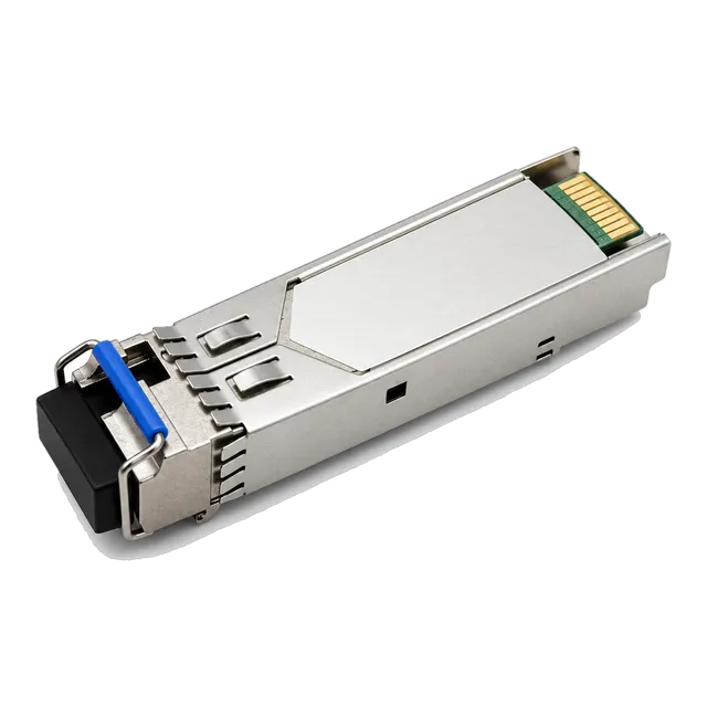
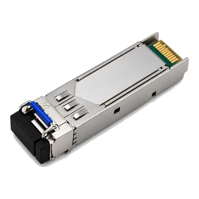
For access and enterprise backhauls, network operators deploy modules like the 1.25G BiDi single-fiber SFP transceiver (1310nm/1550nm) to immediately double fibre utilisation on leased infrastructure without deploying external rack-mounted filter chassis. At higher transmission speeds, the 25G SFP28 BiDi WDM transceiver (1270nm/1330nm) supports 5G fronthaul and midhaul architectures by transmitting 25 Gbps over distances up to 80 km. BiDi deployments require pairing an upstream module (e.g., TX 1270 nm / RX 1330 nm) with an inverted downstream module (TX 1330 nm / RX 1270 nm). Explore our comprehensive 25G SFP28 optical module family for both single-fibre BiDi and standard duplex interfaces.
12Chromatic dispersion and fiber constraints across WDM bands
Chromatic dispersion is the physical phenomenon where different spectral components of an optical pulse travel through optical fibre at slightly different velocities, causing pulses to spread temporally as they propagate. Standard single-mode fibre (ITU-T G.652.D) exhibits a chromatic dispersion coefficient ($D$) of approximately $17\text{ ps/(nm}\cdot\text{km)}$ in the 1550 nm C-band window, but drops to nearly zero in the 1310 nm O-band ($0\text{ to }3.5\text{ ps/(nm}\cdot\text{km)}$).
Because pulse broadening is proportional to the square of the data transmission rate, dispersion constraints escalate sharply from 10G to 25G and 100G per wavelength. At 10 Gbps using non-return-to-zero (NRZ) modulation, an optical signal can traverse approximately 80 km of G.652 fibre before dispersion induces severe inter-symbol interference (ISI). At 25 Gbps NRZ, that uncompensated distance shrinks to roughly 15 km in the C-band. To mitigate dispersion across extended DWDM spans, engineers traditionally deployed lengths of Dispersion Compensating Fibre (DCF), which exhibits a large negative dispersion slope. In modern 100G and 400G DSP-based optics, electronic dispersion compensation integrated directly into the receiver digital signal processor digitally equalises tens of thousands of picoseconds of dispersion, completely removing physical DCF spools from the optical path. For infrastructure background on fibre core types and dispersion characteristics, refer to our single mode fiber cable and transceiver guide.
13Step-by-step commissioning procedure for a passive WDM link
Commissioning a passive wavelength division multiplexing span requires systematic verification of physical optical infrastructure before turning up client-side transceivers. The following procedure ensures link viability and protects sensitive APD receivers from accidental optical over-saturation.
- Characterise the dark fibre path: Perform bi-directional optical time-domain reflectometer (OTDR) traces at both 1310 nm and 1550 nm to record total span loss, verify splice locations, and ensure optical return loss (ORL) exceeds 45 dB across the link.
- Clean and inspect all optical interfaces: Inspect every patch cord bulkhead and transceiver receptacle using an optical inspection microscope conforming to IEC 61300-3-35. Dry-clean connectors using a dedicated optical connector cleaner to eliminate particulate contamination.
- Patch and measure the passive MUX/DEMUX: Mount the passive multiplexers into the equipment racks. Patch the dark fibre link into the Line TX and Line RX ports. Using an optical light source and optical power meter (or optical spectrum analyser), measure insertion loss through each channel port to confirm factory attenuation tolerances.
- Install optical transceivers into host switches: Insert the wavelength-specific transceivers into the host switch ports. Confirm host recognition, verify serial EEPROM tables match host expectations per SFF-8024, and verify via DDM that transmit power levels fall within manufacturer limits.
- Verify receiver optical power: Connect the transceiver TX port to the corresponding MUX channel input. At the remote demultiplexer channel drop port, measure the received optical power with a calibrated power meter before inserting the patch cord into the receiving transceiver RX port. Ensure input power does not exceed the receiver optical damage threshold.
- Monitor post-turn-up link performance: Check host port interface status for bit errors or frame check sequence (FCS) errors. Continuously query DDM RX power readings over a 24-hour soak period to ensure the operating margin remains above 3.0 dB.
14Procurement checklist for WDM optical transceivers and multiplexers
Procuring wavelength division multiplexing hardware requires cross-referencing transceiver electrical specifications with passive optical filter physical performance metrics. Before submitting a formal Request for Quotation (RFQ), procurement and engineering teams should verify each parameter listed in the checklist below.
- Channel Plan and Exact Frequency: For CWDM, specify the exact central wavelengths (e.g., 1470 nm to 1610 nm with 20 nm spacing). For DWDM, specify ITU-T 100 GHz or 50 GHz channel numbers (e.g., Channel 21 to Channel 60) or exact frequency in THz.
- Form Factor and Data Rate: Specify form factor (SFP, SFP+, SFP28, QSFP28, QSFP-DD) matching switch port speeds, ranging from our 100G QSFP28 optical transceiver inventory down to legacy 1.25G interfaces.
- Laser and Receiver Architecture: Delineate whether transmitters require DFB lasers, tunable lasers, PIN receivers, or high-sensitivity APD receivers. Confirm APD overload limits and whether fixed optical attenuators are necessary for short patch testing.
- Host Platform EEPROM Coding: Confirm specific host switch vendor encoding parameters to ensure seamless recognition and prevent port lockdown or non-genuine transceiver warnings.
- Multiplexer Specifications: Verify passband width at -0.5 dB, channel isolation (adjacent >30 dB, non-adjacent >40 dB), insertion loss per port, polarization-dependent loss (PDL <0.2 dB), and whether an integrated 1310 nm wideband port, monitor port (1%), or optical supervisory channel (OSC) is required.
- Operating Temperature Grade: Identify whether transceivers and multiplexers will operate in climate-controlled environments (Commercial: 0 °C to +70 °C) or unconditioned roadside enclosures (Industrial: -40 °C to +85 °C).
15Frequently asked questions
what does wdm mean
WDM stands for wavelength division multiplexing. It is an optical transmission technology that combines multiple data signals on different wavelengths of laser light onto a single optical fibre strand, multiplying network capacity without requiring new physical cabling.
what is wdm
WDM is a method of multiplexing multiple optical carrier signals onto a single optical fibre by using different wavelengths of laser light. This technique enables bidirectional communication over one fibre strand and multiplies capacity across campus, metro, and long-haul networks.
what is dwdm
DWDM stands for dense wavelength division multiplexing. It is a transmission standard defined by ITU-T G.694.1 that packs up to 96 or more optical channels into tight frequency spacings (typically 100 GHz or 50 GHz) within the optical C and L bands.
Can CWDM and DWDM operate over the same fiber strand?
Yes. A hybrid multiplexer can overlay DWDM channels inside the 1530 nm or 1550 nm passband of a standard CWDM filter. The CWDM grid treats the entire DWDM band as a single wide channel, allowing gradual network capacity upgrades.
Why cannot CWDM systems use optical amplifiers?
CWDM channels span 1270 nm to 1610 nm, whereas commercial Erbium-Doped Fibre Amplifiers (EDFAs) only amplify light within the narrow C-band (1528 nm to 1565 nm) and L-band. Wideband amplification across the entire CWDM spectrum is technically unviable and cost-prohibitive.
What is the difference between active and passive WDM?
Passive WDM relies entirely on unpowered optical filters with coloured optical transceivers installed directly in client switches. Active WDM incorporates powered transponders and optical amplifiers to reshape, amplify, and retime optical signals for long-distance transport networks.
Technical review note: confirm model-specific specifications with the product datasheet and the intended host documentation. Product images and application photographs are illustrative.
Discuss this with our team