Single mode fiber delivers virtually limitless bandwidth over long distances by eliminating modal dispersion, but link reliability depends entirely on strict end-face cleanliness, proper connector polish selection, and accurate attenuation budget calculations across standard transmission windows.
01What is single mode fiber and how does it transmit light?
Single mode fiber is an optical transmission medium engineered with a narrow core that permits only one transverse mode of light to propagate along its length. Unlike multimode infrastructure that bounces light across wide internal angles, a single mode optical fiber confines the light wave to a guided spatial mode within a core diameter of approximately 8.3 to 9.2 micrometres (µm). This fundamental physical distinction eliminates intermodal dispersion, enabling signals to travel dozens of kilometres at multi-gigabit rates without the severe pulse-spreading penalties seen in legacy multimode glass.
The outer cladding of standard single mode cable maintains an industry-standard diameter of 125 µm, producing the classic 9/125 µm specification. Surrounding this glass cladding is a primary acrylate protective coating with an outer diameter of 245 to 250 µm, which shields the silica against mechanical abrasion and moisture ingress. Because light travels along a single path parallel to the central axis, optical pulses maintain temporal integrity across extreme link distances. Transmission systems operating across single mode fiber cable rely primarily on optical wavelengths in the infrared spectrum, specifically the 1310 nm O-band and 1550 nm C-band, governed by standards such as ITU-T G.652 and IEEE 802.3.
02Single mode fiber cable core structure and modal dispersion
Single mode fiber cable avoids modal dispersion by maintaining a normalised frequency parameter, known as the V-number, below 2.405. The formula for the V-number is defined as:
V = (2π · a / λ) · NA
where a represents the core radius, λ is the operating wavelength, and NA represents the numerical aperture of the optical core. When the V-number falls below this 2.405 cut-off threshold, higher-order electromagnetic propagation modes cannot be sustained inside the dielectric waveguide. Only the fundamental HE11 mode propagates through the sm fiber core.
Because only one spatial mode travels down the smf fiber cable, modal dispersion drops to zero. However, high-speed single mode optical fiber links remain susceptible to chromatic dispersion, which comprises material dispersion and waveguide dispersion. Chromatic dispersion occurs because distinct spectral components of a laser source travel through silica glass at marginally different group velocities. At 1310 nm, material dispersion and waveguide dispersion cancel each other out in standard sm fiber optic cable, resulting in a near-zero chromatic dispersion coefficient. At 1550 nm, chromatic dispersion rises to roughly 17 to 18 ps/(nm·km), necessitating precise dispersion engineering or dispersion-compensating schemes when deploying 25G, 40G, or 100G optics across extended spans.
03OS1 versus OS2 single mode fiber standards
OS2 single mode fiber is an outdoor and loose-tube optimised specification designed for low attenuation across long distances, whereas OS1 is intended primarily for indoor tight-buffered plant. Standardised under ISO/IEC 11801-1 and TIA-568.3-D, these two categories represent distinctly different attenuation performance thresholds across common operational wavelengths.
The critical difference between OS1 and os2 single mode fiber lies in the elimination of the 1383 nm water-peak attenuation. OS1 cable permits a maximum attenuation of 1.0 dB/km at both 1310 nm and 1550 nm. By contrast, modern os2 sm fiber conforms to ITU-T G.652.D low water-peak specifications, limiting attenuation to a maximum of 0.4 dB/km at 1310 nm and 1383 nm, and 0.3 dB/km at 1550 nm. This low water-peak profile makes os2 fiber cable mandatory for Coarse Wavelength Division Multiplexing (CWDM) architectures, which require usable optical channels spanning from 1271 nm to 1611 nm per ITU-T G.694.2.
| Fiber Classification | ITU-T Specification | Max Attenuation at 1310 nm (dB/km) | Max Attenuation at 1383 nm (dB/km) | Max Attenuation at 1550 nm (dB/km) | Typical Installation Environment |
|---|---|---|---|---|---|
| OS1 | G.652.A / G.652.B | 1.0 | Not specified (high peak) | 1.0 | Indoor tight-buffered riser, < 2 km |
| OS2 | G.652.C / G.652.D | 0.4 | 0.4 | 0.3 | Campus backbone, OSP, data centre fabric |
| Bend-Insensitive OS2 | G.657.A1 / G.657.A2 | 0.4 | 0.4 | 0.3 | High-density patch panels, FTTx drops |
When purchasing modern plant, procurement teams should universally specify os2 fiber optic cable to ensure backward compatibility and prevent transmission bottlenecks in legacy water-peak bands.
04G.652.D versus bend-insensitive G.657 standards
ITU-T G.657 optical fiber defines bend-insensitive performance criteria designed to mitigate macrobending signal loss in high-density routing environments. Standard ITU-T G.652.D smf cable tolerates a minimum bend radius of roughly 30 mm before incurring noticeable optical power loss. When bent tighter than this threshold, light leaks from the core into the cladding, introducing substantial attenuation that can disable high-speed transceivers.
The ITU-T G.657 recommendation addresses this vulnerability by modifying the refractive index profile around the core, often incorporating an optical trench. The standard divides into two main sub-categories:
- G.657.A (A1 and A2): Fully backward-compatible with G.652.D glass. G.657.A1 supports a minimum bend radius of 10 mm with negligible loss. G.657.A2 drops the minimum allowable bend radius down to 7.5 mm, retaining the standard mode field diameter (MFD) of 8.6 to 9.5 µm at 1310 nm to minimise splice loss against existing G.652 plant.
- G.657.B (B2 and B3): Optimised for extreme access and enterprise drop environments. G.657.B3 supports bend radii as tight as 5 mm. However, because its MFD can deviate from G.652.D, fusion splicing to standard trunk infrastructure can incur higher insertion loss.
For data centre top-of-rack patching and structured cross-connects, specifying single mode fiber patch cord assemblies constructed with G.657.A2 glass prevents macrobending link failures caused by congested cable managers or tightly bundled velcro wraps.
05Single mode fiber optic cable construction: loose tube versus tight buffer
Loose-tube and tight-buffered cable designs provide distinct mechanical protection tailored to outdoor routing and indoor distribution respectively. A loose-tube smf fiber optic cable places optical fibres inside rugged plastic buffer tubes filled with water-blocking thixotropic gel or dry super-absorbent yarn. These buffer tubes isolate the fragile silica from external tensile loads, temperature-induced contraction, and crush stresses. Loose-tube constructions represent the standard choice for outside plant (OSP), duct, aerial, and direct-buried runs.
In contrast, tight-buffered single mode cable applies a secondary 900 µm thermoplastic buffer directly over the 250 µm acrylate coating. This direct mechanical support makes tight-buffered smf fiber cable significantly more flexible, easier to terminate directly with field connectors, and ideal for vertical riser shafts and horizontal cable trays. Tight-buffered cable eliminates the need for break-out kits or gel cleaning during termination, significantly reducing deployment labour in enterprise equipment rooms. Modern indoor-outdoor cables blend these traits by encasing dry-blocked loose tubes within a flame-retardant, Low Smoke Zero Halogen (LSZH) jacket that complies with IEC 60332 flame test standards and national building safety codes.
06SMF optical loss mechanisms across transmission windows
Optical attenuation in single mode optical fiber is dominated by Rayleigh scattering, fundamental material absorption, and optical waveguide imperfections. Rayleigh scattering accounts for approximately 90 percent of intrinsic attenuation in the lower transmission windows; it occurs when light scatters off microscopic density fluctuations frozen into the fused silica during glass manufacturing. Because Rayleigh scattering is inversely proportional to the fourth power of the wavelength (1/λ⁴), attenuation drops dramatically as transmission shifts from the 850 nm multimode region down to 1310 nm and 1550 nm.
Material absorption consists of intrinsic absorption caused by the electronic and molecular vibration bands of silica, and extrinsic absorption driven by impurities such as hydroxyl (OH⁻) ions. In older glass, residual OH⁻ molecules formed a pronounced absorption peak near 1383 nm, creating an unusable band. Modern manufacturing techniques dehydrate the preform, eliminating this barrier in standard OS2 glass. Understanding these physical windows is essential when planning optical multiplexing spans, as detailed in our guide on fiber optic wavelengths and transmission windows.
07Single mode fiber patch cord types: UPC versus APC polish
Ultra Physical Contact (UPC) and Angled Physical Contact (APC) define the ferrule end-face geometry on a single mode fiber patch cord, directly dictating optical return loss. UPC connectors utilise a flat or slightly domed polished ferrule face that yields an optical return loss (ORL) of ≥ 50 dB. Light reflecting back from a UPC end-face travels directly into the transmitting laser cavity, which can cause intensity noise and degrade high-frequency signals.
APC connectors incorporate an 8-degree angled end-face that forces reflected light to bounce off the core interface into the cladding, where it attenuates harmlessly. This geometry yields an optical return loss of ≥ 65 dB. Industry colour coding dictates blue connector housings and boots for UPC single mode patch cable assemblies, whereas APC connectors are strictly moulded in green.
APC terminations are mandatory in RF video distribution, passive optical networks (PON), single-fibre bidirectional (BiDi) transmission, and high-power DWDM systems where back-reflection degrades transceiver stability. UPC connectors remain common in standard point-to-point data centre links using duplex LC interfaces. UPC and APC connectors must never be mated together: doing so causes severe physical air gaps, damaging the ferrule end-faces and introducing insertion losses exceeding 4.0 dB.
08Transceiver matching: pairing SM fiber with SFP, SFP28, and QSFP28 optics
Optical transceivers require precise matching to single mode fiber core dimensions, operating wavelengths, and transmission distances to prevent link degradation or optical receiver overload. Single mode transceivers utilise solid-state semiconductor lasers—such as Distributed Feedback (DFB) lasers or Electro-Absorption Modulated Lasers (EML)—engineered to couple tightly into a 9 µm core. Attempting to run single mode optics over 50 µm multimode fibre causes severe differential mode delay (DMD), rendering high-speed digital signals unreadable.
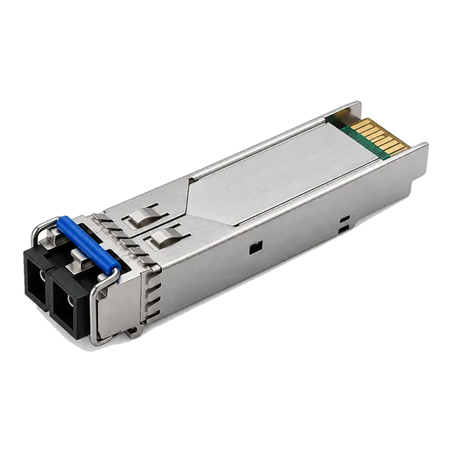
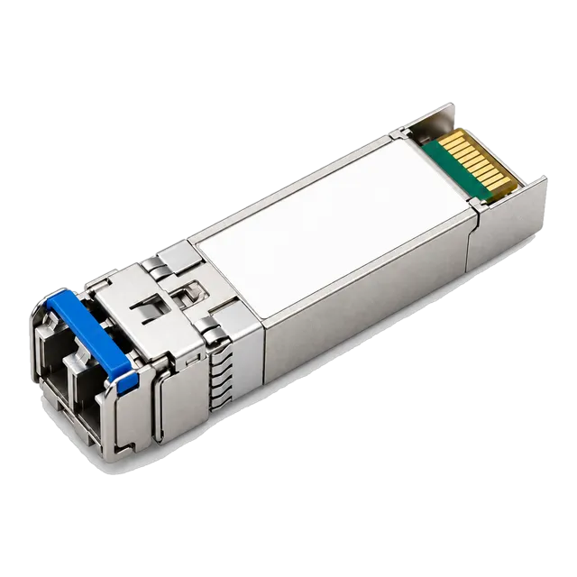
For access and campus aggregations, standard 1.25 Gb/s deployments rely on transceivers such as the 1.25G SFP 1310nm SMF Dual-Fiber Optical Transceiver 10km, which delivers a calibrated power budget over duplex LC single mode fiber patch cable. When scaling enterprise uplinks to 25 Gb/s per IEEE 802.3by, engineers turn to long-reach solutions such as the 25G SFP28 ZR 1310nm 80km Single-Mode Duplex LC Long-Reach module to traverse extended regional links.
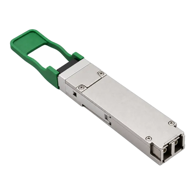
In 100G spine-leaf data centre fabrics, duplex singlemode fiber optic cable interfaces rely on coarse wavelength division architectures. Transceivers like the 100GBASE-CWDM4 QSFP28 1310nm 2-10km Duplex LC SMF DOM transceiver multiplex four 25 Gb/s optical lanes (1271 nm, 1291 nm, 1311 nm, and 1331 nm) onto a single duplex OS2 pair, eliminating the high patch panel real estate overhead associated with multi-fibre parallel MPO cabling. Browse our full range of 100G QSFP28 transceivers for additional core networking solutions.
09Calculating an optical link budget on single mode optical fiber
An optical link budget calculation ensures that total passive attenuation across a single mode optical fiber channel does not exceed the dynamic range between transceiver transmit power and receiver sensitivity. The standard power budget formula is defined as:
P_budget = P_tx(min) - P_rx(sensitivity)
The passive channel insertion loss is calculated using the following parameters per TIA-568.3-D:
Loss_total = (L · α) + (N_conn · IL_conn) + (N_splice · IL_splice) + Margin_safety
Consider a practical enterprise deployment running a 10GBASE-LR link over 12 km of os2 single mode fiber. Review the input parameters below:
- Transmitter Min Launch Power (P_tx): -8.2 dBm
- Receiver Sensitivity (P_rx): -14.4 dBm
- Available Power Budget: -8.2 - (-14.4) = 6.2 dB
- Link Span Length (L): 12.0 km
- Fiber Attenuation at 1310 nm (α): 0.35 dB/km
- Number of Mated Connector Pairs (N_conn): 4 (patch panels and transceivers), rated at 0.5 dB each
- Number of Fusion Splices (N_splice): 2, rated at 0.1 dB each
- Design Safety Margin: 2.0 dB (to account for component ageing and future repair splices)
Now, calculate total link loss:
Loss_cable = 12.0 km · 0.35 dB/km = 4.2 dB
Loss_connectors = 4 · 0.5 dB = 2.0 dB
Loss_splices = 2 · 0.1 dB = 0.2 dB
Loss_total = 4.2 dB + 2.0 dB + 0.2 dB + 2.0 dB = 8.4 dB
In this scenario, total channel loss (8.4 dB) exceeds the transceiver's available budget (6.2 dB) by 2.2 dB. The engineer must either upgrade to a 10GBASE-ER optic with a 15 dB budget, reduce intermediate patch panels, or refine connector losses. For further analysis on avoiding link failure, read our breakdown on optical link budget calculations and range limits.
10Single mode fiber patch cable selection: duplex LC versus simplex BiDi routing
Simplex BiDi routing doubles physical strand efficiency over standard duplex LC single mode fiber patch cable by using two distinct wavelengths over a single glass core. Standard duplex single mode fiber jumpers allocate one strand for transmit (Tx) and the second strand for receive (Rx), both operating on identical nominal wavelengths (e.g., dual 1310 nm paths). This architecture consumes two patch panel ports and two strands per bidirectional link.
Bidirectional (BiDi) transceivers combine Tx and Rx optical signals onto a single strand of smf fiber optic cable through internal wavelength division multiplexing (WDM) diplexers. For example, a 1.25G or 10G BiDi link pairs an upstream optic transmitting at 1310 nm and receiving at 1490 nm with a downstream optic transmitting at 1490 nm and receiving at 1310 nm. Deploying sm fiber patch cables in simplex BiDi topologies cuts fiber trenching costs in half, reclaims congested duct infrastructure, and allows service providers to double client capacity on existing fiber plant. When deploying BiDi systems, engineers must follow a disciplined ordering checklist to ensure correct TX/RX frequency matching, as outlined in our guide to BiDi module pairing rules.
11Inspection, cleaning, and testing standards for smf fiber optic links
IEC 61300-3-35 governs the visual inspection and automated pass/fail criteria for single mode optical fiber connector end-faces. Because the optical core of a single mode fiber cable measures only 9 µm across, a single 2 µm dust particle lodged on the core can cause catastrophic signal reflection, severe insertion loss, or permanent physical damage to ferrule ceramics. Structured testing should follow a defined optical maintenance sequence:
- Visual Inspection: Inspect the connector ferrule using a digital probe microscope set to single mode analysis per IEC 61300-3-35. Check the critical core zone (0 to 25 µm) for pits, chips, and contamination; no scratches or defects are permissible in Zone A.
- Dry Cleaning: If contamination is observed, clean the end-face using a high-grade mechanical click-cleaner or lint-free micro-fibre wipe dry-cleaning method.
- Wet-to-Dry Cleaning: For stubborn oils, use an optical solvent pen followed immediately by a dry wipe across a clean lint-free platen. Re-inspect prior to insertion.
- Tier 1 Testing (OLTS): Measure total insertion loss (IL) and link length using an Optical Loss Test Set (OLTS) with an encircle flux compliant source. Ensure measured loss sits within the calculated loss budget.
- Tier 2 Testing (OTDR): For links exceeding 500 metres, execute bidirectional Optical Time-Domain Reflectometer (OTDR) traces at both 1310 nm and 1550 nm to locate individual event losses, splice anomalies, and excessive macrobending points.
12How to specify single mode fiber optic patch cable assemblies in procurement RFQs
Procurement teams must specify exact mechanical, geometrical, and optical parameters when issuing Requests for Quotation (RFQs) for single mode fiber patch cable assemblies. Vague descriptions such as "standard yellow fiber cable" routinely result in contractors supplying low-grade G.652.A glass with fragile PVC jackets, leading to high failure rates in congested enterprise enclosures. Use the following structured checklist when submitting optical cabling specifications to suppliers:
- Optical Glass Standard: Specify ITU-T G.657.A2 (bend-insensitive, OS2 rated, 9/125 µm) for standard cross-connects and patching. Specify ITU-T G.652.D for raw outside plant trunk reels.
- Connector Configuration: Define connector type and polish independently on each end (e.g., Duplex LC/UPC to LC/UPC, or Simplex SC/APC to LC/UPC).
- Optical Performance Limits: Mandate maximum insertion loss (IL) ≤ 0.20 dB (low-loss grade) or ≤ 0.30 dB (standard grade) per mated pair at 1310 nm and 1550 nm. Mandate return loss (RL) ≥ 50 dB for UPC and ≥ 65 dB for APC.
- Cable Construction and Diameter: Specify outer jacket diameter (e.g., 2.0 mm zipcord, or 1.6 mm uniboot for high-density switches) and core count (simplex, duplex, or breakout).
- Jacket Material and Flammability Rating: Mandate Low Smoke Zero Halogen (LSZH) for European/international sites, or Plenum (OFNP) / Riser (OFNR) for North American building safety compliance.
- Individual Quality Assurance: Demand 100% factory test reports detailing IL, RL, and 3D interferometry geometry (radius of curvature, apex offset, fiber height) included with every production lot.
13Frequently asked questions
What is the core size of a single mode fiber cable?
A single mode fiber cable features a core diameter of approximately 8.3 to 9.2 micrometres (µm), paired with a standard cladding diameter of 125 µm. This is typically written as 9/125 µm. The extremely narrow core ensures that only a single transverse mode of light propagates, eliminating modal dispersion across extended distances.
What is the difference between OS1 and OS2 single mode fiber?
OS1 fiber is designed for indoor tight-buffered applications with maximum attenuation of 1.0 dB/km at 1310 nm and 1550 nm. OS2 is a low water-peak, loose-tube outdoor and enterprise standard conforming to ITU-T G.652.D, limiting attenuation to 0.4 dB/km at 1310 nm and 0.3 dB/km at 1550 nm, making OS2 mandatory for CWDM.
Can I connect a single mode patch cable to a multimode transceiver?
No, you should never connect a single mode patch cable to a standard multimode transceiver. The 9 µm core of single mode glass cannot capture the wide optical output from multimode 850 nm VCSEL lasers, causing extreme insertion losses exceeding 10 to 20 dB, severe modal noise, and immediate transmission failure.
Why are single mode fiber connectors colour-coded blue and green?
The colour indicates the connector end-face polish. Blue connectors designate Ultra Physical Contact (UPC) with a flat polish yielding an optical return loss of ≥ 50 dB. Green connectors designate Angled Physical Contact (APC) with an 8-degree angled end-face yielding an optical return loss of ≥ 65 dB, used primarily in BiDi, PON, and DWDM networks.
What is the maximum reach of 10G over OS2 single mode fiber?
10 Gigabit Ethernet reach over OS2 single mode fiber depends on the transceiver specification. Standard 10GBASE-LR optics reach up to 10 km at 1310 nm. Upgrading to 10GBASE-ER transceivers extends this reach to 40 km at 1550 nm, while 10GBASE-ZR transceivers achieve up to 80 km over engineered OS2 single mode plant.
Technical review note: confirm model-specific specifications with the product datasheet and the intended host documentation. Product images and application photographs are illustrative.
Discuss this with our team