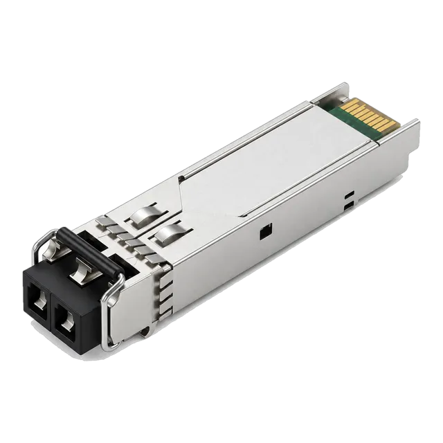
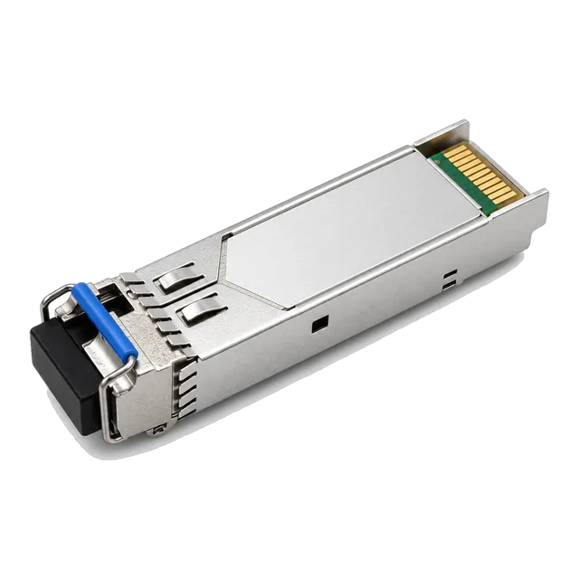
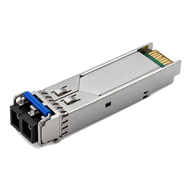
An SX SFP module provides standard 1000BASE-SX multimode Gigabit connectivity up to 550 m over OM2, OM3, or OM4 fibre using an 850 nm VCSEL transmitter, delivering low power dissipation and predictable link budgets for local aggregation links.
01What is an SX SFP module and how does it operate?
An sx sfp module is a hot-pluggable Small Form-factor Pluggable optical transceiver engineered for short-reach Gigabit Ethernet data links over multimode optical fibre. Operating under the IEEE 802.3z 1000BASE-SX standard, the module transmits and receives data at an optical signalling line rate of 1.25 Gb/s. The physical interface uses a standard duplex LC optical receptacle, housing an 850 nm Vertical-Cavity Surface-Emitting Laser (VCSEL) transmitter paired with a high-sensitivity PIN receiver photodiode.
Network architects deploy the 1000base sx sfp transceiver module inside data centre server cabinets, campus building distributor rooms, and enterprise access switches. Unlike long-wavelength transceivers such as the 1000BASE-LX standard detailed in our 1000BASE LX SFP transceiver guide, an SX optical module relies exclusively on graded-index multimode glass (MMF). For cost-effective horizontal building cabling, the GLC-SX-MM 1.25G SFP 850nm 550m Multimode 1000BASE-SX module establishes links between core aggregation chassis and access switches with minimal host power draw.
02Core technical specifications of the 1000BASE SX SFP
A standard 1000base sx sfp delivers a maximum raw data rate of 1.25 Gb/s to accommodate standard 8B/10B encoding, yielding an effective Ethernet payload throughput of 1.0 Gb/s. The electrical interface follows the SFF-8431 and SFF-8074i specifications, consuming no more than 0.8 W to 1.0 W of power under full operational load from a regulated 3.3 V host power bus.
The optical transmitter operates across a spectral band centred at 850 nm, with an allowable wavelength window spanning 830 nm to 860 nm and a maximum root-mean-square (RMS) spectral width of 0.85 nm. According to IEEE 802.3z Clause 38, the minimum optical output launch power is -9.5 dBm, while the maximum launch power is capped at -3.0 dBm to avoid saturating receiving photodetectors. Receiver sensitivity down to -17.0 dBm ensures stable bit error ratios (BER < 10⁻¹²) over enterprise backbone paths. For procurement teams standardising inventory, our multi-reach 1.25G Gigabit SFP Transceiver portfolio covers both 550 m multimode variants and extreme single-mode links.
03How far can an SX SFP module transmit across OM1, OM2, OM3, and OM4?
Maximum transmission distance for an sx sfp module is bounded by the modal bandwidth of the installed multimode fibre core rather than pure optical attenuation. Modal dispersion occurs because different optical modes travel along paths of varying lengths inside a graded-index multimode core, broadening pulses until symbols overlap. The modal bandwidth is measured in Megahertz-kilometre (MHz·km) and dictates link distances under IEEE 802.3z Clause 38 specifications.
Legacy OM1 cable featuring a 62.5 µm core diameter provides a minimum overfilled launch (OFL) modal bandwidth of 200 MHz·km at 850 nm, capping reliable link distances at 220 m. Standard 50 µm OM2 fibre raises bandwidth to 500 MHz·km, extending transmission reach to 550 m. Laser-optimised 50 µm OM3 (2000 MHz·km) and OM4 (4700 MHz·km) assemblies easily sustain this 550 m ceiling with significantly higher channel margin, though the IEEE standard sets the maximum reach for 1000BASE-SX at 550 m regardless of higher OM3 and OM4 modal margins. Facilities selecting between glass categories should review our Single Mode vs Multimode Fiber guide to prevent premature cabling obsolescence.
04Multimode transmission distance comparison
Evaluating fiber grades side-by-side demonstrates why core diameter and modal bandwidth determine operational limits for every sfp 1g sx transceiver in structured cabling plants.
| Fibre Category | Core Diameter (µm) | Modal Bandwidth (MHz·km @ 850nm) | Maximum Attenuation (dB/km) | Max Reach (m) | Minimum Link Budget (dB) |
|---|---|---|---|---|---|
| OM1 (TIA-492AAAA) | 62.5 | 200 | 3.5 | 220 | 7.5 |
| OM2 (TIA-492AAAB) | 50.0 | 500 | 3.0 | 550 | 7.5 |
| OM3 (TIA-492AAAC) | 50.0 | 2000 | 3.0 | 550 | 7.5 |
| OM4 (TIA-492AAAD) | 50.0 | 4700 | 3.0 | 550 | 7.5 |
While OM3 and OM4 cables sustain 10GBASE-SR and 25GBASE-SR speeds up to 300 m and 400 m respectively, an installed sx sfp module operates reliably across all four grades up to the limits detailed above without requiring conditioning patches.
05Link budget calculation for a 1000base sx sfp transceiver
Calculating optical power margins ensures an installed 1000base sx sfp transceiver link does not suffer packet drops from excessive insertion loss or degraded modal bandwidth. To evaluate optical link safety, calculate the available optical power budget (P_avail) and subtract all discrete insertion losses across the channel.
Consider an enterprise backbone link spanning 400 m of OM3 multimode fiber containing four mated LC connector pairs and two mechanical splice points:
- Transmitter minimum launch power (P_tx_min): -9.5 dBm
- Receiver optical sensitivity (P_rx_sens): -17.0 dBm
- Total available optical power budget: P_avail = -9.5 dBm - (-17.0 dBm) = 7.5 dB
- Fibre attenuation at 850 nm: 400 m × 3.0 dB/km = 1.20 dB
- Connector insertion losses: 4 pairs × 0.35 dB/pair (TIA-568 limit) = 1.40 dB
- Splice losses: 2 splices × 0.10 dB/splice = 0.20 dB
- Modal dispersion and inter-symbol interference penalty: 1.00 dB
- Total channel insertion loss: 1.20 dB + 1.40 dB + 0.20 dB + 1.00 dB = 3.80 dB
- Net optical margin: 7.5 dB - 3.80 dB = 3.70 dB
A surplus margin of 3.70 dB comfortably satisfies the recommended 3.0 dB operational safety margin, ensuring resilient connectivity despite patch cord bending or field connector wear.
06Understanding the difference: GLC-SX-MM vs GLC-SX-MMD
The core distinction between legacy glc sx mm modules and modern glc sx mmd optics is the integration of Digital Diagnostic Monitoring (DDM). Early optical modules identified by the glc mmd predecessor code provided only static identification data over standard two-wire I2C bus communications, leaving technicians blind to actual physical line conditions.
The suffix 'D' denotes real-time diagnostic telemetry implemented according to SFF-8472 industry specifications. A glc sx mmd transceiver samples internal analog signals via an integrated microcontroller, digitising internal operating parameters that host switches read directly. This real-time access enables engineers to monitor transceiver temperature, supply voltage, transmitter bias current, transmitted optical power (Tx), and received optical power (Rx). For field deployment diagnostics, engineers can learn how to interpret telemetry metrics in our guide to what DDM can tell you about an optical link.
07Real-time diagnostic metrics in SFF-8472 DDM
Digital Optical Monitoring (DOM) compliant with SFF-8472 maps real-time telemetry into designated two-wire interface memory addresses (I2C address A2h). Five continuous parameters allow proactive failure prevention across the optical distribution frame:
- Operating Temperature: Calibrated internally, typically operating across standard commercial (0°C to +70°C) or industrial (-40°C to +85°C) bands.
- Supply Voltage: Monitors the host switch rail against nominal 3.3 V DC, with standard alarm trip points below 3.0 V or above 3.6 V.
- Laser Bias Current: Measures the DC drive current supplied to the 850 nm VCSEL. Elevated bias current over time indicates semiconductor degradation and impending transmitter failure.
- Tx Optical Output Power: Reports emitted optical power into the transmitting LC receptacle, alerting operators if the launch level drops below -9.5 dBm.
- Rx Optical Power: Quantifies incoming light at the photodiode. When received power drops below -17.0 dBm, the transceiver triggers an Rx Low Warning before link degradation causes interface flaps.
08SX vs LX: selecting the right Gigabit transceiver
Choosing between an sx sfp module and a 1000BASE-LX transceiver hinges on existing plant cabling, intended path lengths, and overall project budget. While an sx sfp module functions solely across 850 nm multimode fibre up to 550 m, a 1000BASE-LX transceiver utilizes a 1310 nm Fabry-Pérot (FP) laser to traverse single-mode fibre (SMF) up to 10 km or 20 km.
For campus trunk routes exceeding 550 m, 1000BASE-LX models such as the 1.25G SFP 1310nm SMF Dual-Fiber Optical Transceiver 10km are mandatory. While 1000BASE-LX can drive legacy OM1 or OM2 multimode fiber over 550 m using an IEEE 802.3z compliant mode-conditioning patch cable, deploying standard SX transceivers remains far more economical for rack-to-rack, top-of-rack, and floor-to-floor multimode distribution links.
09Host compatibility and EEPROM programming requirements
Physical compliance with SFF-8074i mechanical dimensions does not guarantee an sx sfp module will establish a link in managed host hardware. Proprietary network equipment vendors implement vendor verification algorithms inside switch operating systems, reading the serial EEPROM located at I2C address A0h upon module insertion.
This EEPROM stores vendor name, Vendor Specific ID (OUI), part identification codes, serial numbers, and a cyclic redundancy checksum (CRC). If the programmed vendor credentials fail the switch security check, the host port enters an error-disabled state, logging messages such as 'unsupported transceiver'. MARS manufactures MSA-compliant optics programmed with platform-matched microcode, ensuring seamless boot recognition and complete CLI telemetry access across all major enterprise routing and switching architectures.
10Procurement checklist for SX SFP module deployments
Procurement teams should verify mechanical, optical, and environmental requirements against concrete project parameters before placing volume orders for any 1000base sx sfp transceiver module:
- Fibre Core Diameter: Confirm whether field patch bays contain 50/125 µm (OM2, OM3, or OM4) or 62.5/125 µm (OM1) cabling to ensure distance limits (550 m vs 220 m) are not breached.
- Optical Connectors: Verify patch panels terminate in UPC polished duplex LC connectors. Standard SX transceivers do not mate with angled APC ferrules.
- Operating Temperature Grade: Specify Commercial (0°C to +70°C), Extended (-20°C to +85°C), or Industrial (-40°C to +85°C) to withstand unconditioned outdoor roadside cabinets or industrial plant floors.
- Host Vendor Matrix: Provide specific switch chassis models and software release versions to verify EEPROM coding requirements prior to factory flashing.
- Telemetry Access: Require SFF-8472 compliant DDM support to ensure remote network monitoring teams can track link margins continuously.
11Installation best practices and optical maintenance
Maintaining high optical return loss and minimal attenuation on an sx sfp module requires strict fibre hygiene and careful mechanical handling during installation. Because 850 nm multimode light features a core diameter of 50 µm to 62.5 µm, microscopic dust particles and skin oils deposited on ferrule end faces generate severe scattering loss.
Always follow clean-and-inspect procedures using dry lint-free 1.25 mm click-cleaners before seating LC patch cables into the transceiver optical bore. Protective dust caps should remain inserted in unused transceiver ports at all times to shield internal VCSEL lenses from airborne contaminants. When extracting modules, release the bail latch fully to 90 degrees before pulling outward; attempting to pull the transceiver by the patch cord damages internal LC receptacle pins and strains the host SFP cage solder joints.
12Request your customised optical transceiver quotation
When specifying high-density switch upgrades or long-term spares inventory, sourcing tested, fully coded optical modules guarantees link performance while controlling procurement expenditure. Shanghai Mars Industrial Co., Ltd. supplies fully compliant optical transceivers, media converters, and copper interconnects tested across tier-one switch environments.
Access our free online link budget calculator to verify loss margins across your optical plant, or review our broad range of interface configurations in the transceiver selection guide. For volume pricing, custom EEPROM coding requests, or technical data sheets, contact our technical sales team at inquiry@optical-module-factory.com or connect via WhatsApp at +86 176 2154 1688.
13Frequently asked questions
Can an SX SFP module work over single-mode fibre?
No, an SX SFP module cannot operate over single-mode fibre. The 850 nm VCSEL laser source and optical launch optics are designed specifically for 50 µm and 62.5 µm multimode cores. Attempting to couple an SX transmitter into a 9 µm single-mode fibre core produces excessive insertion loss and immediate link failure.
What is the maximum distance for a 1000BASE-SX SFP?
The maximum standard distance for a 1000BASE-SX SFP module is 550 m when operated over 50/125 µm OM2, OM3, or OM4 multimode fibre. When connected to legacy 62.5/125 µm OM1 multimode cabling, the maximum reach is limited to 220 m due to lower modal bandwidth.
What is the difference between GLC-SX-MM and GLC-SX-MMD?
The primary difference is Digital Diagnostic Monitoring (DDM/DOM). GLC-SX-MM is a legacy specification without live optical telemetry. GLC-SX-MMD incorporates SFF-8472 compliant diagnostic capabilities, allowing host switches to report real-time operating temperature, laser bias current, supply voltage, transmitted optical power, and received optical power.
Does a 1000BASE-SX transceiver work in an SFP+ port?
Most dual-speed 1G/10G SFP+ switch ports support 1000BASE-SX transceivers, provided the host switch operating system supports manual port speed configuration to 1000 Mb/s. However, dedicated 10G-only SFP+ ports will not establish a link with a 1.25 Gb/s SX SFP module.
What connector type does an SX SFP module use?
An SX SFP module uses a standard duplex LC optical receptacle with a Physical Contact (PC) or Ultra Physical Contact (UPC) flat polish. It cannot accept Angled Physical Contact (APC) green connectors, as the angled ferrule causes excessive optical reflection and physical mis-mating inside the transceiver.
Technical review note: confirm model-specific specifications with the product datasheet and the intended host documentation. Product images and application photographs are illustrative.
Discuss this with our team