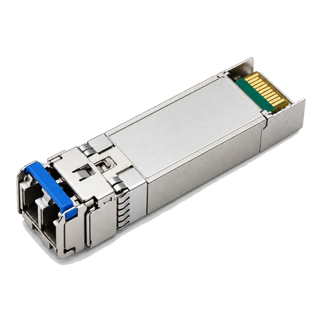
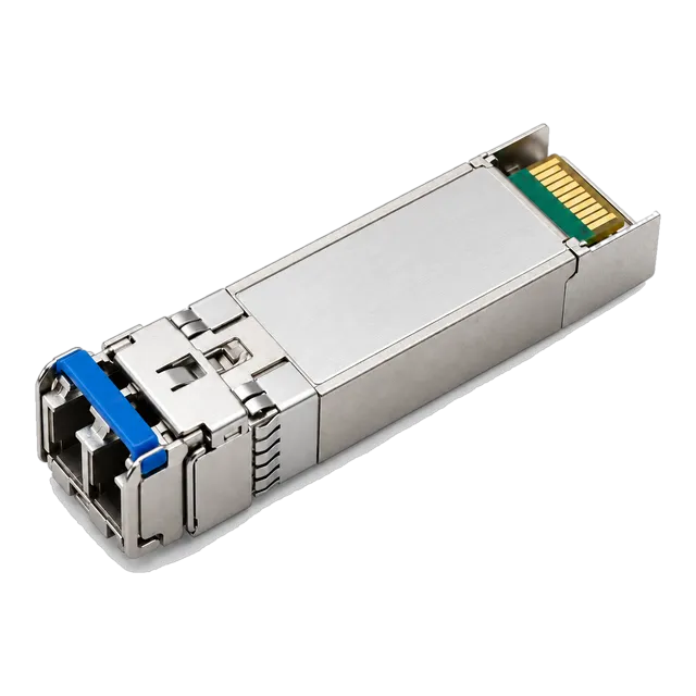
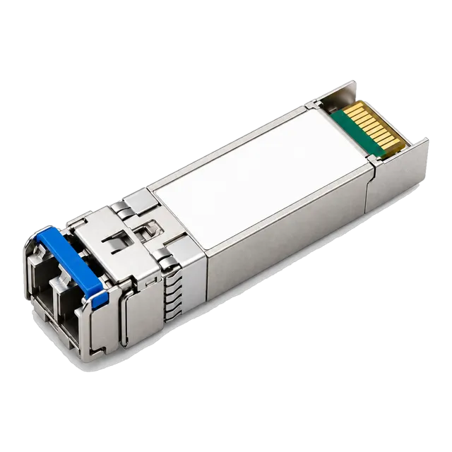
Choose multimode OM4 fiber for short-reach switch interconnects inside 100 metres to exploit lower-cost VCSEL transceivers, but deploy single-mode OS2 fiber for campus backbones and runs over 150 metres to eliminate modal dispersion and avoid future recabling.
01Core differences: single mode vs multimode fiber
The core distinction in single mode vs multimode fiber lies in the physical diameter of the optical core and the number of light modes permitted to propagate through the glass. Single-mode optical fiber (SMF) incorporates a narrow core of approximately 8.3 to 9.0 micrometres (µm) surrounded by a 125 µm outer cladding. This tiny aperture forces light to travel exclusively along a single transverse spatial mode, virtually eliminating intermodal dispersion. In contrast, multimode optical fiber (MMF) features a significantly broader core—standardised at 50 µm for modern Laser-Optimised Multimode Fiber (OM2, OM3, OM4, OM5) or 62.5 µm for legacy cabling (OM1)—which enables multiple optical propagation modes simultaneously.
Understanding this monomode vs multimode architecture dictates your entire physical layer design. While multimode fiber accepts light from divergent optical sources across broader numerical apertures, each propagating mode travels a marginally different path length. This structural reality creates modal dispersion, placing strict constraints on transmission range at high signalling rates. When designing structured cabling systems or specifying pluggable optical modules, evaluating mm fiber vs sm fiber ensures that link budgets conform to strict international standards such as ISO/IEC 11801 and IEEE 802.3.
02Difference between single mode and multimode fiber physical construction
The physical construction of optical glass establishes how light rays refract and propagate down the internal core. Both cable types maintain an identical outer cladding diameter of 125 µm to preserve mechanical strength and standardise termination ferrules, but their internal index profiles differ completely.
Monomode optical fiber employs a step-index or matched-clad core with an extremely narrow numerical aperture (typically 0.13 to 0.14). Because the optical path diameter approximates the operating wavelength, light propagates parallel to the optical axis without bouncing off core-cladding boundaries. Modern telecommunications networks standardise on ITU-T G.652.D non-dispersion-shifted fiber or bend-insensitive ITU-T G.657.A1/A2 glass, ensuring low bending loss in high-density patch panels.
Multimode fiber relies on a graded-index profile where the refractive index decreases parabolically from the central axis out to the cladding boundary. This parabolic gradient accelerates light modes travelling on outer paths, compensating partially for their longer physical distance relative to axial modes. Nevertheless, differential mode delay (DMD) remains the primary physical impairment governing multimode fiber and single mode fiber difference, fundamentally restricting the transmission ceiling for multi-gigabit data streams.
03Operating wavelengths and optical light sources
Multimode optical systems operate primarily in the 850 nm and 1300 nm wavelength windows, whereas single-mode links leverage transmission bands centred at 1310 nm, 1550 nm, and across the Coarse and Dense Wavelength Division Multiplexing (CWDM/DWDM) spectrum from 1270 nm to 1610 nm.
The difference in light generation technology between these media families directly influences active hardware costs:
- Multimode transceivers (e.g., 10GBASE-SR, 25GBASE-SR): These modules deploy Vertical-Cavity Surface-Emitting Lasers (VCSELs). Operating at 850 nm, VCSELs feature circular beam emission profiles that couple directly into a 50 µm core without complex beam-shaping optics. Legacy 100BASE-FX and low-speed systems historically deployed surface-emitting light-emitting diodes (LEDs) at 1300 nm, though these lack the modulation bandwidth required for Gigabit and multi-gigabit traffic.
- Single-mode transceivers (e.g., 1000BASE-LX, 10GBASE-LR, 25GBASE-LR): These optics require edge-emitting semiconductor lasers, including Fabry-Perot (FP) and Distributed Feedback (DFB) lasers for intermediate reaches, or Electro-Absorption Modulated Lasers (EMLs) for amplified long-distance routes. Coupling laser energy into a 9 µm core demands sub-micron mechanical alignment tolerances and integrated optical isolators to prevent back-reflections from damaging the semiconductor cavity.
For detailed wavelength channel spacing across optical transport systems, consult our fiber optic wavelengths and transmission windows guide.
04How far can multimode fiber go across modern data rates?
Multimode fiber can carry data across distances ranging from 30 metres to 2,000 metres, but the reachable span contracts rapidly as lane transmission rates increase. At a modest 1.25 Gb/s rate (1000BASE-SX), an OM2 or OM3 multimode fiber optic distance routinely reaches 550 m. However, advancing to modern data centre line rates exposes severe multimode distance limitations driven by modal dispersion.
The transmission reach for standardised multimode grades depends entirely on the effective modal bandwidth (EMB) measured in MHz·km at 850 nm:
| Ethernet Standard | Line Rate | OM1 (62.5/125) | OM2 (50/125) | OM3 (50/125) | OM4 (50/125) | OM5 (50/125) |
|---|---|---|---|---|---|---|
| 1000BASE-SX | 1.25 Gb/s | 275 m | 550 m | 550 m | 550 m | 550 m |
| 10GBASE-SR | 10.31 Gb/s | 33 m | 82 m | 300 m | 400 m | 400 m |
| 25GBASE-SR | 25.78 Gb/s | Not supported | Not supported | 70 m | 100 m | 100 m |
| 40GBASE-SR4 | 41.25 Gb/s (4×10G) | Not supported | Not supported | 100 m | 150 m | 150 m |
| 100GBASE-SR4 | 103.1 Gb/s (4×25G) | Not supported | Not supported | 70 m | 100 m | 100 m |
As illustrated, at 25 Gbps and 100 Gbps, multimode reaches cap at 100 m over OM4 even when using Reed-Solomon Forward Error Correction (RS-FEC). Enterprise networks operating high-throughput links increasingly bypass MMF limitations entirely, selecting modern transceivers like our 25G SFP28 optical transceiver module series to standardise their data distribution layer.
05Single mode fiber distance and long-reach capabilities
Single mode fiber distance spans from 2 kilometres to more than 120 kilometres on a single span without intermediate optical amplification. Because monomode optical fiber guides light along a single spatial path, intermodal dispersion is zero; optical reach is bounded instead by chromatic dispersion and glass attenuation.
Standard single-mode OS2 cabling specified to ITU-T G.652.D exhibits maximum fiber attenuation of 0.4 dB/km at 1310 nm and 0.25 dB/km at 1550 nm. This low attenuation profile enables vast geographic links:
- Short single-mode (10 km to 20 km): Standard 10GBASE-LR and 25GBASE-LR optics using 1310 nm DFB lasers cover campus distribution loops and regional backbones. Products such as our 25G SFP28 LR 1310nm 10km transceiver deliver reliable 10 km reach across OS2 patch and trunk cabling.
- Extended reach (40 km): ER-designated optics (e.g., 10GBASE-ER, 25GBASE-ER) employ cooled DFB or EML transmitters operating at 1310 nm or 1550 nm to overcome structural path losses up to 15–18 dB.
- Long distance fiber optic cable reaches (80 km to 120 km): ZR models and ultra-long-reach transceivers utilize 1550 nm cooled EML transmitters paired with Avalanche Photodiode (APD) receivers. For demanding inter-city links, single mode fiber range extends to 80 km on 25G links with optics like our 25G SFP28 ZR 80km single-mode transceiver.
For an in-depth review of single-mode cable standards, bend tolerances, and specifications, review our single mode fiber cable and optical transceiver guide.
06MM fiber vs SM fiber: transceiver optics architecture and cost
Transceiver manufacturing complexity accounts for the persistent pricing discrepancy between single mode vs multi mode fiber optic active interfaces. While raw single-mode cabling costs marginally less per metre than multi-mode glass due to mass global production for telecom utilities, multimode transceivers cost considerably less to manufacture than their single-mode counterparts.
A short-reach 850 nm VCSEL diode requires a relatively simple semiconductor wafer fabrication process and yields high output efficiency with minimal drive current. Furthermore, the 50 µm target core of multimode patch cabling provides a generous mechanical coupling margin; spatial tolerances during manufacturing alignment can vary by several micrometres without triggering catastrophic insertion loss.
Conversely, single-mode optical transceivers rely on precision TO-can or box-type laser packaging with micro-lenses to collimate and focus laser emission onto a 9 µm target. The laser diode must maintain narrow spectral widths (often <1 nm spectral line width for DFB devices) and require integrated internal thermo-electric coolers (TEC) in extended-reach modules to prevent wavelength drift. Consequently, single-mode optics carry a cost premium of 30% to 150% over comparable multimode transceivers at 10G and 25G rates.
07Optical link budget comparison: a worked attenuation calculation
A structured optical link budget calculation proves whether an optical channel will operate within transceiver receiver sensitivity limits across its design lifetime. Below is a worked engineering calculation comparing a 10 Gb/s link deployed over 300 m of OM4 multimode fiber against the same link deployed over 300 m of OS2 single-mode fiber.
Example 1: 10GBASE-SR across 300 m OM4 (850 nm)
- Transmitter minimum launch power: -7.3 dBm (IEEE 802.3ae Table 52-7)
- Receiver sensitivity: -9.9 dBm (stressed sensitivity)
- Available optical power budget: -7.3 dBm - (-9.9 dBm) = 2.6 dB
- Cable attenuation: 3.0 dB/km × 0.3 km = 0.90 dB
- Connector losses (2 mated LC pairs @ 0.35 dB each): 0.70 dB
- Splice losses (0 splices): 0.00 dB
- Total channel insertion loss: 0.90 dB + 0.70 dB = 1.60 dB
- Link safety margin remaining: 2.6 dB - 1.60 dB = 1.00 dB
Example 2: 10GBASE-LR across 300 m OS2 (1310 nm)
- Transmitter minimum launch power: -8.2 dBm (IEEE 802.3ae Table 52-12)
- Receiver sensitivity: -14.4 dBm
- Available optical power budget: -8.2 dBm - (-14.4 dBm) = 6.2 dB
- Cable attenuation: 0.4 dB/km × 0.3 km = 0.12 dB
- Connector losses (2 mated LC pairs @ 0.35 dB each): 0.70 dB
- Splice losses (2 fusion splices @ 0.1 dB each): 0.20 dB
- Total channel insertion loss: 0.12 dB + 0.70 dB + 0.20 dB = 1.02 dB
- Link safety margin remaining: 6.2 dB - 1.02 dB = 5.18 dB
The single-mode link yields a substantial 5.18 dB margin versus 1.00 dB on multimode, illustrating why single-mode cabling absorbs patch panel additions and plant ageing without link drops. You can calculate custom fiber topologies using our online optical link budget calculator or read our technical guide on optical link budget calculations.
08Jacket colours, connector types, and polish specifications
Standardised jacket colour coding per TIA-598-D allows technicians to visually identify optical cabling types in dense cable trays, eliminating cross-connection errors between single and multimode fiber assemblies. The exterior jacketing conventions define:
- Yellow: Single-mode fiber (OS1 indoor, OS2 outdoor/loose-tube/universal).
- Orange: Legacy multimode fiber (OM1 62.5/125 µm and OM2 50/125 µm).
- Aqua: OM3 laser-optimised 50/125 µm multimode fiber.
- Erika Violet (Magenta): OM4 laser-optimised 50/125 µm multimode fiber (predominant in European installations; North America frequently utilises aqua for OM4).
- Lime Green: OM5 wideband multimode fiber (designed for Short Wavelength Division Multiplexing, SWDM).
Connector polish standards must match transceiver ports precisely. Multimode transceivers interface exclusively with Ultra Physical Contact (UPC) flat-polished ferrules, terminated via LC duplex or MPO/MTP connectors. Single-mode transceivers standardise on UPC (blue connectors) for standard point-to-point duplex optics, or Angled Physical Contact (APC, green connectors, polished at an 8-degree angle) for single-fiber BiDirectional (BiDi), Passive Optical Network (PON), and high-power long-reach systems where optical return loss (ORL) must exceed 60 dB to prevent laser instability.
09Can you connect single mode fiber to multimode fiber directly?
Directly connecting single-mode fiber to multimode fiber without specialized conditioning optics is strictly prohibited in enterprise networks. Mating an SMF patch cord directly into an MMF infrastructure or transceiver causes severe optical mismatch and unrecoverable link corruption.
When light passes from single-mode glass into a multimode core, the narrow 9 µm beam launches into a tiny spatial fraction of the 50 µm or 62.5 µm core. In legacy 1000BASE-LX systems over 62.5 µm fiber, this off-axis or central launch triggers Differential Mode Delay (DMD), creating severe jitter and inter-symbol interference. Overcoming this specific condition requires a specialised Mode Conditioning Patch Cord (MCP) conforming to IEEE 802.3z Clause 38, which offsets the single-mode core precisely by 17–23 µm.
Conversely, launching light from a multimode fiber into a single-mode core induces catastrophic aperture loss. Due to the geometric reduction from a 50 µm core to 9 µm, over 80% to 90% of the optical energy is lost directly at the ferrule interface, generating an immediate 15 dB to 20 dB insertion loss that overwhelms the receiver budget.
10Total cost of ownership: cabling plant versus active optics
Evaluating the total cost of ownership (TCO) between multimode and single-mode systems requires modelling the entire link life-cycle over a 10-to-15 year operational period. Historically, engineers treated multimode as the default campus and data centre technology due to lower optical transceiver pricing, but line rates of 25 Gbps, 100 Gbps, and 400 Gbps have altered this capital expenditure balance.
In high-density top-of-rack (ToR) to leaf-switch configurations under 30 metres, Direct Attach Copper (DAC) cables or multimode Active Optical Cables (AOC) remain the most economical choices. Between 30 and 100 metres inside enterprise data halls, multimode optics (such as 100GBASE-SR4) coupled with Base-8 or Base-12 MPO trunk cables maintain an initial transceiver cost advantage.
However, for spine-leaf backbones, inter-building campus routing, and runs exceeding 100 metres, deploying OS2 single-mode fiber delivers lower lifetime TCO. Single-mode cabling handles infinite bandwidth expansion without physical recabling. Migrating from 10G to 100G or 400G on single-mode requires changing only the end transceivers, whereas multimode trunks often demand cable replacement or complex parallel MPO trunking to offset severe distance penalties.
11Decision matrix: selecting the right optical fiber for your network
This decision matrix provides concrete selection criteria for IT infrastructure directors, systems integrators, and network design engineers specifying structured fiber projects.
| Deployment Scenario | Typical Distance | Recommended Fiber | Transceiver Architecture | Primary Design Reason |
|---|---|---|---|---|
| Intra-rack switch-to-server | < 5 m | Direct Attach Copper (DAC) | Integrated twinax passive | Lowest latency, lowest power (<0.1 W), lowest cost |
| High-density row interconnect | 5 m to 30 m | Active Optical Cable (AOC) | Multimode integrated assembly | Flexible routing, lightweight, factory-terminated reliability |
| Enterprise data centre hall | 30 m to 100 m | Multimode OM4 | 850 nm VCSEL (SR / SR4) | Optimal transceiver capital expenditure per port |
| Campus building riser / backbone | 100 m to 300 m | Single-Mode OS2 | 1310 nm DFB (LR / CWDM) | Eliminates modal dispersion; future-proofs 100G+ upgrades |
| Inter-building campus loops | 300 m to 10 km | Single-Mode OS2 | 1310 nm DFB / BiDi | Immunity to ground potential; low attenuation across splices |
| Metro and ISP backhaul | 10 km to 80 km | Single-Mode OS2 / G.652.D | 1550 nm cooled EML / ZR | Chromatic dispersion-managed optical transmission |
To cross-reference transceiver form factors against host switch platform requirements, browse our transceiver selector tool before completing your equipment schedules.
12Engineering checklist for specifying fiber transceivers and plant in an RFQ
When preparing a formal Request for Quotation (RFQ) for optical transceivers, structured glass, and patch leads, specify explicit engineering parameters rather than generic marketing terms. Use this checklist to verify link parameters before procurement:
- Core and Fiber Standard: State the exact ITU-T or ISO/IEC standard (e.g., ITU-T G.652.D OS2 for single-mode; ISO/IEC 11801 OM4 laser-optimised for multimode).
- Operating Wavelength: Define optical transmission channels (e.g., 850 nm for SR; 1310 nm for LR; 1270/1330 nm for 10G BiDi simplex links).
- Connector Type and Polishing: Require duplex LC/UPC for standard transceivers, MPO-12/UPC (Base-8 pinned) for SR4 transceivers, or LC/APC for single-fiber BiDi transceivers.
- Optical Power Budget: Document minimum transmitter launch power (dBm), receiver saturation limit (overload in dBm), and receiver sensitivity (dBm) to prevent receiver damage or link dropouts.
- Digital Diagnostics Monitoring (DDM/DOM): Ensure modules comply with SFF-8472 to monitor real-time temperature, optical transmit/receive power, and supply voltage in host management software.
- Operational Temperature: Specify Commercial (0°C to 70°C), Extended (-20°C to 85°C), or Industrial grade (-40°C to 85°C) based on equipment room climate controls.
If you require custom host platform EEPROM encoding or need assistance calculating loss budgets for your optical bill of materials, submit your project details via our engineering contact page for direct technical support.
13Frequently asked questions
how far can multimode fiber go
Multimode fiber transmits data up to 2,000 metres at 100 Mb/s, 550 metres at 1 Gb/s over OM2, OM3, or OM4, and 400 metres at 10 Gb/s over OM4. At 25 Gb/s and 100 Gb/s line rates, multimode reaches cap at 70 metres on OM3 and 100 metres on OM4.
what is the main difference between single mode and multimode fiber
The primary difference is core diameter and propagation behaviour. Single-mode fiber has a tiny 9 µm core transmitting a single optical ray with zero modal dispersion across tens of kilometres. Multimode fiber has a 50 µm core carrying multiple light rays simultaneously, which restricts reach to short-distance data centre runs.
can i mix single mode and multimode fiber in the same link
No, you cannot directly connect single-mode and multimode fiber. Launching light from a 50 µm multimode core into a 9 µm single-mode core causes an immediate 15 dB to 20 dB loss. Transitioning between fiber types requires an optical media converter or optical transceivers matched to each respective cable plant.
is single mode fiber more expensive than multimode fiber
Single-mode raw cable is marginally cheaper per metre than multimode cable due to massive telecommunications manufacturing scale. However, single-mode optical transceivers cost 30% to 150% more than multimode transceivers because edge-emitting semiconductor lasers and tight internal optical alignment tolerances demand precision manufacturing compared to 850 nm VCSEL optics.
why do single mode and multimode patch cables have different jacket colours
Jacket colours follow the TIA-598-D standard to prevent accidental cross-connection. Single-mode OS1 and OS2 patch leads are yellow. Multimode cables are colour-coded by generation: OM1 and OM2 are orange, OM3 is aqua, OM4 is typically Erika violet (or aqua in North America), and OM5 wideband fiber is lime green.
Technical review note: confirm model-specific specifications with the product datasheet and the intended host documentation. Product images and application photographs are illustrative.
Discuss this with our team