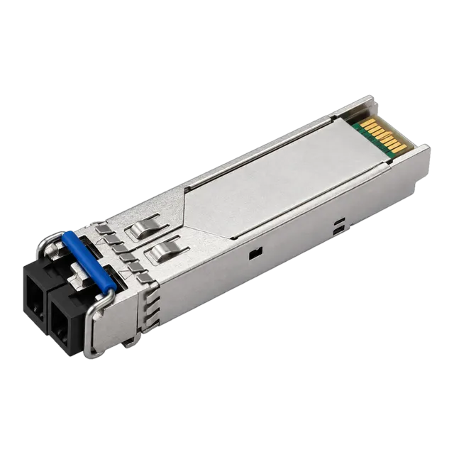
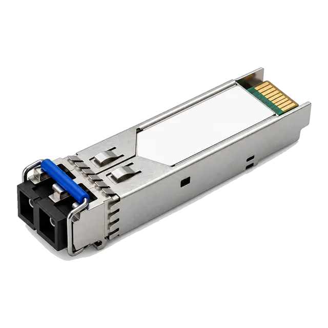
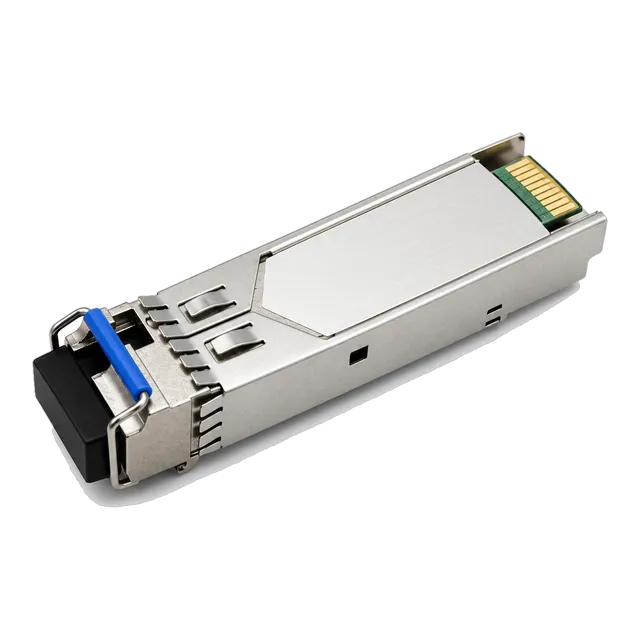
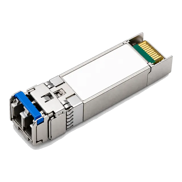
The SFP LC connector remains the enterprise and carrier standard for modular transceivers up to 25 Gbps per lane, demanding rigorous ferrule inspection, exact polarity management, and precise insertion loss budgeting to maintain optical link integrity.
01What defines an optical SFP LC connector interface?
An sfp lc connector optical interface uses a standardised 1.25 mm ceramic ferrule and push-pull latching mechanism to terminate optical fiber links directly into pluggable transceiver modules. Originally developed by a major equipment manufacturer and standardised under IEC 61754-20 and TIA-604-10 (FOCIS 10), the LC connector halved the physical footprint of legacy SC connectors, allowing equipment manufacturers to pack up to 48 optical ports into a single 1RU switch panel. Within a Small Form-factor Pluggable (SFP) transceiver cage, the LC optical receptacle connects the patch lead directly to the internal Transmitter Optical Sub-Assembly (TOSA) and Receiver Optical Sub-Assembly (ROSA).
The physical dimensions defined by the SFP Multi-Source Agreement (MSA) allocate a front-facing port envelope that perfectly accommodates a duplex LC receptacle. Whether operating at 1.25 Gbps Gigabit Ethernet, 10 Gbps SFP+, or 25 Gbps SFP28, transceivers using the LC interface preserve identical physical dimensions while migrating the internal optics across distinct transmission speeds. For an overview of how LC compares to other modular plugs across the industry, review our guide on which type of connectors do SFP transceivers use.
02SFP LC connector
The SFP LC connector serves as the standard optical receptacle defined by the Small Form Factor Committee to couple light between network fiber patch leads and transceiver sub-assemblies. The mechanical design incorporates a precision cylindrical ceramic (zirconia) ferrule with an outer diameter of exactly 1.25 mm, held to dimensional tolerances tighter than ±0.5 µm. This ferrule aligns the fiber core—measuring 9 µm in single-mode fiber (SMF) or 50 µm in multimode fiber (MMF)—directly with the micro-lenses of the optical sub-assemblies inside the transceiver housing.
Retention relies on an RJ45-style latching tab that clicks into the transceiver receptacle with an audible engagement, resisting axial pull forces up to 100 N without dislodging. When deploying high-density switching fabrics, this latch ensures the connector remains seated despite thermal expansion, cooling fan vibration, and bundle weight inside vertical cable managers. Understanding these mechanical pinouts and optical alignments is critical when engineering transceiver layouts; see our detailed breakdown in the SFP connector types, pinouts, and optics guide.
03Duplex versus simplex SFP transceiver lc connector designs
An sfp transceiver lc connector configuration functions as either a duplex interface using separate transmit and receive ports or a simplex BiDi interface routing two wavelengths over a single optical bore. Duplex transceivers feature two side-by-side LC receptacles spaced at a pitch of 6.25 mm. One port receives light into the ROSA, while the adjacent port emits light from the TOSA. Standard duplex modules such as the 1.25G SFP Transceiver Module 1310nm 10/20km Duplex LC DDM use this arrangement to transmit and receive concurrently across two dedicated strands of fiber.
In contrast, single-strand bidirectional (BiDi) transceivers utilize a simplex LC port. A BiDi module incorporates an internal diplexer prism or optical filter that directs outgoing light from an on-board laser (such as 1310 nm) down the fiber while separating incoming light of a different wavelength (such as 1550 nm or 1490 nm) into the internal photodiode detector. For example, the 1.25G BiDi Single-Fiber SFP Transceiver 1310nm/1550nm 20km Simplex LC cuts outside plant fiber consumption in half by terminating a duplex communications path over one simplex LC patch connection.
04SFP module lc connector ferrule types: UPC versus APC polish
An sfp module lc connector uses an Ultra Physical Contact (UPC) flat polish for standard datacom transceivers or an Angled Physical Contact (APC) 8-degree polish where back-reflection must be kept below -60 dB. The physical contact geometry dictates how light reflects at the glass-to-air or glass-to-glass boundary. UPC ferrules are polished with a spherical dome perpendicular (0 degrees) to the fiber axis, yielding an optical return loss (ORL) of ≥50 dB. APC ferrules feature an 8-degree mechanical angle that reflects stray optical energy into the cladding rather than back towards the transmitter laser, delivering an ORL of ≥60 dB.
Plugging an APC connector (identifiable by its green housing or strain-relief boot) into a standard UPC transceiver port (identifiable by blue connector bodies) damages the ceramic ferrule end faces and creates an air gap with up to 4.0 dB insertion loss. Standard Ethernet SFP, SFP+, and SFP28 transceivers almost universally specify UPC interfaces. APC LC interfaces are primarily reserved for passive optical networks (PON), radio access networks (CPRI/eCPRI), and long-reach analog video links where back-reflections cause laser chirp and bit errors.
05Selecting an LC LC SFP patch cable by fiber core and reach
Selecting an lc lc sfp patch cable requires matching the optical fiber glass geometry—either 9 µm single-mode or 50 µm multimode—to the transmitter wavelength and modal dispersion limits of your transceiver. Duplex LC-to-LC patch leads interconnect switch transceivers, structured patch panels, and optical distribution frames (ODF). A mismatched core size introduces severe attenuation: connecting an 850 nm multimode transceiver using a 9 µm single-mode LC lead will attenuate over 80 percent of optical power due to numerical aperture mismatch.
For multimode installations, OM3 (aqua jacket) and OM4 (magenta or Erika violet jacket) laser-optimised fibers carry 850 nm signals over reach limits governed by modal dispersion: OM3 supports 10GBASE-SR up to 300 m, whereas OM4 extends this to 400 m. For single-mode transceivers, standard yellow-jacketed cables conforming to ITU-T G.652.D or bend-insensitive ITU-T G.657.A1 fiber must be specified. For higher-rate access links, modules such as the SFP-2.5G-LX20 2.5G Single-Mode 1310nm 20km Duplex LC require G.652.D single-mode LC leads to maintain pulse integrity across campus and metro spans.
06Optical insertion loss and return loss specifications across LC connections
Optical insertion loss across an LC mated pair typically ranges from 0.10 dB to 0.30 dB, while optical return loss must exceed 50 dB for UPC polishes and 60 dB for APC polishes according to IEC 61753-1. Insertion loss measures the optical power dropped across the mated ferrule interface due to axial misalignment, lateral displacement, end-face separation, and core concentricity errors. High-grade factory-terminated LC connectors achieve Grade B insertion loss (≤0.12 dB mean, ≤0.25 dB max for 97% of connections) under IEC 61753-1 standards.
The table below provides standard optical performance specifications across standard LC connector interfaces:
| Connector Interface | Polish Type | Standard Return Loss (dB) | Typical Insertion Loss (dB) | Max Insertion Loss (dB) | Mechanical Durability (Cycles) |
|---|---|---|---|---|---|
| LC Multimode (OM4) | PC (0°) | ≥30 | 0.15 | 0.30 | 500 matings |
| LC Single-Mode (OS2) | UPC (0°) | ≥50 | 0.15 | 0.30 | 500 matings |
| LC Single-Mode Low Loss | UPC (0°) | ≥55 | 0.10 | 0.15 | 1000 matings |
| LC Single-Mode Angled | APC (8°) | ≥60 | 0.18 | 0.35 | 500 matings |
Exceeding these attenuation limits across structured patching reduces the available optical power margin, potentially driving the receiver below its minimum sensitivity threshold.
07Calculating optical link budgets and operating margins for LC links
Calculating an optical link budget requires subtracting total fiber attenuation, connector losses, splice losses, and safety margins from the difference between transceiver minimum launch power and minimum receiver sensitivity. Operating long-reach links without calculating this power envelope risks link failure or optical receiver overload. You can model link parameters using our online link budget calculator to ensure positive operating margins before purchasing cabling hardware.
Consider an engineered link using a high-power long-reach module, such as the 25G SFP28 ZR 1310nm 80km Single-Mode Duplex LC Transceiver, deployed across a 70 km span of ITU-T G.652.D single-mode fiber with four intermediate LC patch panels:
- Transmitter Minimum Launch Power (TX Min): +0.0 dBm
- Receiver Sensitivity (RX Min): -24.0 dBm
- Total Available Optical Power Budget: 0.0 - (-24.0) = 24.0 dB
- Fiber Attenuation (70 km @ 0.32 dB/km at 1310 nm): 22.40 dB
- LC Connector Loss (5 mated pairs @ 0.20 dB/pair): 1.00 dB
- Fusion Splice Loss (4 splices @ 0.05 dB/splice): 0.20 dB
- Total Link Attenuation: 22.40 + 1.00 + 0.20 = 23.60 dB
- Operating Power Margin: 24.0 dB - 23.60 dB = 0.40 dB
Because the resulting 0.40 dB operating margin is below the recommended 3.0 dB safety margin, this link requires either upgrading to ultra-low-loss fiber (0.28 dB/km), reducing patch hops, or switching to a 1550 nm transmission window with lower fiber attenuation (0.19 dB/km). For further analysis on budget variances, read why a 20 km module may not reach 20 km.
08LC connector inspection and cleaning protocols under IEC 61300-3-35
The IEC 61300-3-35 standard defines visual inspection pass/fail criteria for the 1.25 mm ferrule end face of an LC connector across four concentric optical zones. Dust particles, skin oils, and airborne hydrocarbons contaminate the 9 µm core area of a single-mode fiber upon exposure to air, resulting in high insertion loss or permanent pitting from laser power concentration. Never plug an LC patch cable into an SFP port without scoping and cleaning both mating surfaces.
- Inspect the optical end face: Use a 200x or 400x fiber inspection microscope probe to verify that Zone A (core: 0 to 25 µm diameter) has zero scratches and zero defects under IEC 61300-3-35 SMF requirements.
- Perform dry cleaning: Insert a dedicated 1.25 mm mechanical push-action cleaning tool into the transceiver optical bore or over the LC cable ferrule, pushing until the micro-woven ribbon rotates and clicks.
- Perform wet-to-dry cleaning if contamination persists: Apply a drop of optical-grade solvent (such as high-purity hydrofluoroether) to a lint-free optical wipe, drag the LC ferrule across the moist spot onto a dry area, and clear the residue.
- Re-inspect the ferrule: Scope the surface a second time to ensure Zone A and Zone B (cladding: 25 to 115 µm) are completely free of particles before final mating.
09High-density cable management and uniboot LC assemblies
Uniboot LC patch cords combine both transmit and receive fiber strands into a single round 2.0 mm jacket to reduce patch panel congestion by roughly 50 percent compared to standard duplex zipcord assemblies. In traditional zipcord patch cables, two parallel 2.0 mm or 3.0 mm jackets are joined side-by-side, obstructing switch exhaust vents and cluttering high-density cable trays in top-of-rack (ToR) architectures.
In addition to airflow advantages, uniboot LC assemblies feature tool-less polarity reversal. When commissioning links, a common fault occurs when transmit (TX) connects to transmit (TX) rather than receive (RX). Standard duplex clips require cutting the plastic yoke to swap positions. Modern uniboot connectors feature flip-latch housings that allow an engineer to rotate the internal ferrules 180 degrees in seconds without exposing the glass cores. Learn more about deploying these assemblies in our guide on LC uniboot connectors for high-density architectures.
10Using DDM telemetry to diagnose LC connector interface faults
Digital Diagnostic Monitoring (DDM) provides real-time telemetry on transceiver optical transmit power, optical receive power, laser bias current, module temperature, and supply voltage in accordance with SFF-8472. This internal diagnostic system allows engineers to pinpoint optical interface degradation directly from the host switch Command Line Interface (CLI) without dispatching an optical power meter into the data hall.
When an LC connector interface experiences contamination or misalignment, the DDM telemetry reports an immediate drop in RX Optical Power (measured in dBm or µW) while the TX Optical Power remains stable at nominal levels. If the connector ferrule is partially unseated, DDM typically reveals erratic RX power fluctuations whenever adjacent cables are moved. Furthermore, tracking Laser Bias Current provides early warnings of optical sub-assembly aging: if bias current escalates significantly to maintain constant TX power, optical reflection from a damaged or poorly polished LC end face may be feeding back into the laser cavity.
11Transceiver connector comparison matrix across modular optical form factors
Modular optical transceivers use LC, SC, and MPO connector interfaces depending on physical port width, data rate, and parallel optical lane configurations. While LC dominates single-channel optics up to 25 Gbps, multi-channel and ultra-high-speed transceivers employ higher-density optical interfaces.
The following table contrasts the key physical and operational parameters of primary optical transceiver connectors:
| Connector Standard | Ferrule Diameter (mm) | Fiber Channels | Form Factors Used | Standard Data Rates | Common Applications |
|---|---|---|---|---|---|
| LC Duplex | 1.25 | 2 (1 TX, 1 RX) | SFP, SFP+, SFP28, QSFP-LR4 | 1 Gbps to 100 Gbps | Enterprise LAN, SAN, Metro DCI |
| LC Simplex | 1.25 | 1 (BiDi WDM) | SFP, SFP+, SFP28, QSFP28 | 1 Gbps to 100 Gbps | FTTx, 5G Front-haul, Fiber Exhaust |
| SC Duplex / Simplex | 2.50 | 1 or 2 | Legacy GBIC, 1x9, PON ONTs | 100 Mbps to 1.25 Gbps | Legacy Telecom, EPON, GPON OLT |
| MPO-12 / 16 | Mechanical MT | 8, 12, or 16 | QSFP+, QSFP28, QSFP-DD | 40 Gbps to 400 Gbps | Hyperscale Spine-Leaf, Parallel SR4 |
| CS Connector | 1.25 (Dual) | 2 (Reduced Pitch) | QSFP-DD, OSFP | 100 Gbps to 400 Gbps | Next-Gen High-Density Breakout |
While MPO interfaces dominate parallel short-reach multimode links in hyperscale facilities, duplex LC remains the most ubiquitous connector for campus, enterprise, and service provider core switching.
12Engineering checklist for specifying SFP LC connectors in an RFQ
An optical procurement Request for Quotation (RFQ) for SFP modules with LC interfaces must explicitly state data rate, operating wavelength, optical reach, ferrule polish, DDM capability, and host platform EEPROM coding. Omitting connector polish or temperature tolerances often leads to procurement mismatches that delay network rollouts.
Engineers and procurement teams should verify the following parameters prior to releasing an RFQ:
- Transceiver Form Factor and Speed: SFP (1.25G), SFP+ (10G), or SFP28 (25G).
- Optical Receptacle Type: Duplex LC (standard 2-fiber) or Simplex LC (BiDi single-fiber).
- Ferrule Polish Geometry: UPC (standard flat polish, blue) or APC (8° angled, green).
- Fiber Glass Compatibility: Single-Mode (9/125 µm OS2) or Multimode (50/125 µm OM4).
- Wavelength and Reach: Exact nominal wavelengths (e.g., 850 nm for 300 m, 1310 nm for 10/20 km, 1550 nm for 80 km, or BiDi transmit/receive wavelength pairs).
- Operating Temperature Grade: Commercial Temperature (0°C to +70°C), Extended (-20°C to +85°C), or Industrial Grade (-40°C to +85°C).
- DDM / DOM Implementation: Fully compliant with SFF-8472 real-time monitoring.
- Host Platform Compatibility: Coded EEPROM memory tables matching a major switch vendor or the host platform profile.
13Commissioning and verifying your LC optical link
Commissioning an LC optical link requires verifying physical end-face cleanliness, confirming TX/RX polarity alignment, and measuring received optical power against the transceiver receiver dynamic range. Taking a systematic approach during initial installation prevents intermittent bit error rate (BER) issues and avoids permanent laser damage caused by receiver saturation.
- Verify physical containment: Ensure optical dust caps remain on transceivers and patch leads until the exact second of mating. Never leave an open LC transceiver bore exposed to ambient data centre air.
- Inspect and clean: Scope every LC ferrule end face using an IEC 61300-3-35 certified visual tool, clean if necessary, and re-scope to ensure a zero-defect core.
- Establish link polarity: Seat the duplex LC connector into the transceiver cage until the latch engages. Check that the port LINK LED illuminates. If the LED remains dark, verify polarity using a visual fault locator (VFL) or rotate the uniboot polarity housing.
- Review DDM receive levels: Access the switch CLI and run the optical diagnostic transceiver command. Compare the reported RX Optical Power against the transceiver minimum sensitivity and receiver overload limits. If the RX power is within 3 dB of receiver overload (typical on short links using 40 km or 80 km optics), install a calibrated inline fixed LC optical attenuator immediately.
14Frequently asked questions
What is an SFP LC connector?
An SFP LC connector is an optical interface standard that couples an LC fiber optic patch lead to a Small Form-factor Pluggable (SFP) transceiver. It uses a 1.25 mm ceramic ferrule and a push-pull latching mechanism to secure optical connections for Gigabit, 10G, and 25G Ethernet.
Can I plug an LC APC cable into an SFP transceiver?
You should not plug an LC APC cable into a standard SFP transceiver. Most standard Ethernet SFP transceivers feature UPC flat optical receptacles. Connecting an angled 8-degree APC ferrule to a UPC port causes physical core damage, high insertion loss, and severe optical signal degradation.
What is the difference between duplex LC and simplex LC on an SFP?
Duplex LC SFP transceivers have two LC ports side-by-side, dedicating one fiber strand to transmitting light and the second to receiving light. Simplex LC transceivers, commonly called BiDi modules, use a single LC port to transmit and receive concurrently across one fiber strand using two distinct wavelengths.
How much insertion loss is normal for an SFP LC connector?
A standard SFP LC connector mated pair typically introduces between 0.10 dB and 0.30 dB of optical insertion loss. High-grade factory-terminated single-mode LC connectors generally maintain insertion losses below 0.15 dB, in accordance with IEC 61753-1 Grade B specifications.
How do I reverse polarity on an LC duplex patch cord?
To reverse polarity on a standard duplex LC cord, remove the plastic outer retention clip, swap the positions of the A and B connector bodies, and snap the clip back on. On modern uniboot LC patch cables, polarity is reversed by opening the latch housing and rotating the ferrules 180 degrees without tools.
Why is my SFP link down even though the LC cable is connected?
The most common causes of link failure on an LC connection are inverted polarity (TX connected to TX instead of RX), contaminated ferrule end faces blocking light, or an optical power level below receiver sensitivity. Check the switch CLI DDM values to verify whether the transceiver is receiving optical power.
Technical review note: confirm model-specific specifications with the product datasheet and the intended host documentation. Product images and application photographs are illustrative.
Discuss this with our team