The LC uniboot connector consolidates duplex transmission into a single round 2.0 mm jacket, cutting cable volume by 50 percent while enabling rapid, tool-less polarity reversal across high-density optical transceivers.
01What is an LC uniboot connector and how does it function?
An lc uniboot connector consolidates two distinct optical fibres into a single round cable jacket terminating in a unified duplex housing with standard 1.25 mm ferrules. In traditional optical patching, duplex transmission relies on zipcord cabling—two distinct simplex jackets bonded together in a flat, figure-8 profile. The lc uniboot architecture eliminates this dual-jacket footprint by carrying both transmit (Tx) and receive (Rx) fibres within a single 2.0 mm or 1.5 mm round jacket, dividing them only inside the plug body immediately behind the ceramic ferrules.
This mechanical packaging adheres strictly to the optical interface geometries defined in IEC 61754-20, ensuring full physical interoperability with any standard duplex LC optical transceiver receptacle. By condensing two jacketed paths into one round profile, network operators reduce structured cabling bulk while preserving the mechanical integrity, bend radius, and optical performance required by IEEE 802.3 ethernet standards.
02LC uniboot connector mechanical architecture and ferrule pitch
The mechanical interface of the lc uniboot connector maintains the standard LC ferrule centre-to-centre pitch of 6.25 mm while redesigning the internal strain relief and housing. Within the rear of the connector body, an internal anti-snag crimp ring anchors the aramid yarn (Kevlar) tensile strength members evenly around the circumference of the single round cable. This design provides minimum tensile loading retention of 70 N per IEC 61753-1, preventing optical microbending during routing.
Inside the connector body, the two colour-coded tight-buffered fibres (typically 900 μm or 600 μm outer diameter) are segregated into dedicated channels leading to precision zirconium dioxide (ZrO2) ceramic ferrules. Because the rigid housing maintains the exact 6.25 mm spacing, the assembly couples securely into MSA-compliant transceiver optical ports, such as those found on 10G SFP+ optical transceivers and 25G SFP28 transceivers, without placing torsional or angular stress on the transceiver bore.
03Cable tray capacity: worked calculation of fill ratio savings
Deploying round uniboot cabling cuts structured pathway area consumption by approximately 50 to 60 percent compared to standard duplex zipcord. Pathway utilisation is governed by the total cross-sectional area of the cable bundles against the usable area of the wire mesh tray or raceway.
Consider a high-density zone distribution rack routing 288 duplex channels (576 fibres) through an overhead basket tray. We compare standard figure-8 zipcord cable against round uniboot cable:
- Standard 2.0 mm zipcord: Cross-section per cable = 2.0 mm × 4.1 mm = 8.20 mm². Total raw area for 288 links = 2,361.6 mm². Applying a standard 50 percent packing density factor (NEC 0.5 raceway fill factor), total pathway area required = 4,723.2 mm².
- Round 2.0 mm uniboot: Outer diameter = 2.0 mm. Cross-section per cable = π × (1.0 mm)² = 3.14 mm². Total raw area for 288 links = 904.3 mm². Applying the same 50 percent packing factor, total pathway area required = 1,808.6 mm².
The net physical pathway reduction is 2,914.6 mm², representing a 61.7 percent reduction in occupied cross-sectional area. In terms of weight, standard 2.0 mm zipcord averages 7.2 kg per kilometre per duplex link (2.07 kg for 288 ten-metre runs), whereas 2.0 mm uniboot averages 3.8 kg per kilometre (1.09 kg for 288 ten-metre runs). This yields an overhead suspension weight reduction of 47.3 percent across the patch zone.
04Reversing polarity on an LC uniboot patch lead
Field polarity reversal on an lc uniboot connector is performed without cutting fibre, exposing bare glass, or utilising specialized fusion tools. Standard optical links operate on an A-to-B polarity scheme (Tx to Rx). In high-density patching environments, changes in patch panel trunking configurations frequently necessitate flipping a patch cord from A-to-B crossover to A-to-A straight-through orientation. Traditional duplex cords require disassembling individual connector housings or splitting zipcord webbing.
- Release the rear housing: Slide back or unlatch the external boot or secondary locking clip situated behind the main connector plug.
- Expose the ferrule carriers: Pivot or rotate the connector outer shell cover upward to access the keyed 1.25 mm ferrule retaining blocks.
- Rotate the pitch positions: Swap ferrule position A with ferrule position B. Depending on the mechanical design, this is achieved either by rotating the internal ferrule carrier 180 degrees around its central axis or by popping the individual ferrule retainers out of their track and transposing them into the adjacent slot.
- Re-engage the primary latch: Snap the outer housing cover back into its closed detent until an audible click confirms engagement.
- Secure the boot: Slide the rear boot forward over the retaining clips to prevent accidental rotation under tensile load.
This process takes under thirty seconds per end, eliminating the risk of damaging the internal fibres or altering the factory-inspected ferrule end-face geometry.
05Thermal impact and airflow dynamics in high-density racks
High cable bulk in front of high-density switch exhausts increases thermal impedance and forces equipment cooling fans to draw more electrical power. Front-to-back and side-to-side airflow schemes require uninhibited pathways across switch faceplates. A 48-port switch populated with 10GBASE-SR or 25GBASE-SR optics and standard duplex zipcords introduces 48 individual 2.0 × 4.1 mm webbing cables across a 1RU faceplate (44.45 mm height).
This bundle blocks approximately 393 mm² of active ventilation opening. When substituted with 2.0 mm uniboot cables, the physical obstruction drops to 151 mm², restoring 61.5 percent of previously restricted faceplate clearance. In data centre facilities operating according to ASHRAE TC 9.9 thermal guidelines, reduced front-plate static pressure drop translates directly to lower fan RPM requirements, cutting parasitic power consumption across top-of-rack (ToR) switching infrastructure.
06Optical performance: insertion loss and return loss specifications
The optical attenuation of an lc uniboot connector must satisfy the performance criteria defined in IEC 61753-1 and TIA-568.3-D. Consolidating two fibres into a single boot does not compromise optical transmission, provided the ferrule end faces maintain precise concentricity, apex offset below 50 μm, and fibre undercut/protrusion within ±50 nm.
| Connector Class | Polishing Type | Mean Insertion Loss (dB) | Max Insertion Loss (dB) | Minimum Return Loss (dB) |
|---|---|---|---|---|
| Multimode Standard (OM4) | PC (0°) | 0.15 | 0.30 | ≥ 30 |
| Multimode Low-Loss (OM4) | PC (0°) | 0.08 | 0.15 | ≥ 35 |
| Singlemode Standard (OS2) | UPC (0°) | 0.18 | 0.30 | ≥ 50 |
| Singlemode Low-Loss (OS2) | UPC (0°) | 0.10 | 0.20 | ≥ 55 |
| Singlemode Angled (OS2) | APC (8°) | 0.12 | 0.25 | ≥ 65 |
To ensure link stability across complex channels, link loss budgets must account for connector degradation over mating cycles. Quality uniboot assemblies guarantee durability exceeding 500 mating cycles with insertion loss shift below 0.10 dB. Use our optical link budget calculator to confirm whether your channel margins accommodate your planned patch points.
07Connector variants: push-pull tabs versus standard latch boots
Push-pull tab uniboot connectors resolve physical finger-access limitations in ultra-high-density patch environments where port pitch is compressed. In standard LC connections, latch disengagement requires pressing a top-mounted flexible trigger lever with a finger or specialized extraction tool. In a 48-port 1RU patch panel or an optical blade chassis with stacked transceiver cages, the spacing between adjacent connectors is frequently less than 5 mm, making lever depression difficult and risking accidental disconnection of neighbouring links.
Push-pull uniboot connectors incorporate an extended, flexible pull-tab mechanically linked to the internal connector latch. Pulling the tab rearward applies direct, linear force to the release mechanism, disengaging the latching ramp from the transceiver optical bore without requiring manual access to the connector body itself. This mechanism reduces extraction time, avoids mechanical strain on the host transceiver cage, and prevents damage to neighbouring patch cables during moves, adds, and changes (MACs).
08Transceiver interface compatibility across SFP+, SFP28 and QSFP
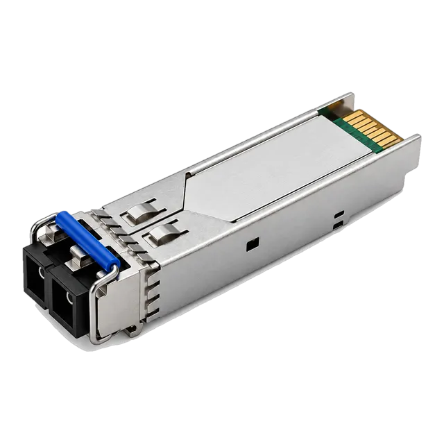
An lc uniboot connector is mechanically and optically compatible with all standard duplex LC optical transceivers compliant with SFF-8432 and SFF-8472 specifications. Duplex modules—such as 10GBASE-LR, 25GBASE-LR, and 100GBASE-CWDM4 duplex modules—employ standard optical duplex ports that accept any compliant LC plug. To learn more about matching form factors to network layers, read our guide on how to choose the right optical transceiver for your network.
However, when evaluating single-fibre systems, engineers must distinguish between duplex architectures and BiDi modules. Single-fibre BiDi transceivers utilise a simplex LC port requiring a simplex patch lead rather than a duplex uniboot cord. Review our BiDi modules pairing checklist before finalising physical interface choices for single-strand infrastructure.
09Comparative analysis: standard duplex zipcord versus LC uniboot
Selecting between standard duplex zipcord and uniboot designs depends on rack density, field management requirements, and budget constraints. The following decision matrix highlights the operational differences across five key parameters.
| Parameter | Standard Duplex Zipcord (2.0 mm) | LC Uniboot (2.0 mm) | Push-Pull LC Uniboot (2.0 mm) |
|---|---|---|---|
| Cable Profile | Flat dual-jacket (figure-8) | Single round jacket | Single round jacket with pull tab |
| Outer Dimensions (mm) | 2.0 × 4.1 | 2.0 Ø | 2.0 Ø |
| Pathway Footprint | Baseline (100%) | Reduced (approx. 40%) | Reduced (approx. 40%) |
| Polarity Reversal | Disassemble clip or slice zip | Tool-less rotatable housing | Tool-less rotatable housing |
| High-Density Switch Extraction | Difficult below 10 mm spacing | Moderate (standard latch) | Superior (linear pull-tab release) |
| Bend Radius Multi-Axis | Asymmetric (stiff across major axis) | Isotropic (equal in all axes) | Isotropic (equal in all axes) |
While standard zipcord cabling remains viable for simple point-to-point cross-connects with low port density, uniboot assemblies are the operational standard for spine-leaf top-of-rack architectures where airflow, pathway volume, and quick maintenance are critical.
10Patch field procurement checklist for high-density deployments
When specifying lc uniboot connector assemblies for data centre structured cabling or enterprise core switching, procurement documentation must detail critical optical and mechanical metrics. Ensure your bill of materials captures these specifications before issuing an RFQ, referencing our guide on how to prepare a useful optical networking BOM:
- Fibre Glass Core Type: State ITU-T G.657.A1/A2 bend-insensitive singlemode (minimum bend radius 10 mm or 7.5 mm) or ISO/IEC 11801 OM4 bend-insensitive multimode.
- Cable Jacket Outer Diameter: Specify 2.0 mm for standard tray distribution or 1.5 mm/1.6 mm for ultra-dense intra-rack interconnects.
- Jacket Material Rating: Mandate Low Smoke Zero Halogen (LSZH) per IEC 60332-1 or Plenum (OFNP) per NFPA 262 depending on local building codes.
- Polarity Reversal Design: Require tool-less, non-destructive polarity reversal mechanisms that do not expose bare glass fibres.
- Extraction Mechanism: Specify push-pull tabs for any application exceeding 24 ports per rack unit.
- Factory Test Certification: Demand 100 percent factory interferometric verification of ferrule geometry (end-face radius of curvature, apex offset, fibre height) along with insertion loss and return loss test reports.
11Integrating uniboot patch cords with optical transceiver links
Deploying the lc uniboot connector across enterprise and service-provider networks ensures cleaner rack topology, improved thermal efficiency, and simplified polarity management. To avoid optical link margin failure, verify that your channel loss calculations account for all intermediate patch points, cassettes, and transceivers using our optical link budget calculation guide.
For structured patching design support, transceiver compatibility verification, or production-grade optical BOM quoting, contact our technical engineering team at optical-module-factory.com.
12Frequently asked questions
What is an LC uniboot connector?
An LC uniboot connector combines two optical fibres into a single round cable jacket terminated in a dual-ferrule LC housing. This design replaces traditional flat duplex zipcord, reducing cable volume by up to 50 percent and permitting tool-less polarity reversal.
Can I reverse polarity on an LC uniboot connector without tools?
Yes, modern LC uniboot connectors are designed for tool-less polarity reversal. An engineer simply releases the outer housing cover, rotates or swaps the internal ferrule positions 180 degrees, and snaps the shell back into place, flipping the transmit and receive paths in seconds.
Are LC uniboot connectors compatible with standard SFP+ and SFP28 transceivers?
Yes, LC uniboot connectors conform strictly to IEC 61754-20 and SFF-8432 mechanical dimensions. The 6.25 mm ferrule pitch matches the optical port spacing on standard duplex LC transceivers, including 10G SFP+, 25G SFP28, and 100G duplex transceivers.
What is the difference between an LC uniboot and a push-pull uniboot?
A standard LC uniboot features an integrated top latch lever requiring manual finger depression to uncouple. A push-pull uniboot adds an extended rear pull-tab linked to the latch, enabling quick disengagement from high-density switch ports without needing finger access between tight connectors.
How does an LC uniboot connector improve rack airflow?
By housing both fibres in a single 2.0 mm round jacket instead of a 2.0 x 4.1 mm zipcord, uniboot cables reduce cabling cross-sectional footprint by over 60 percent. This reduction decreases faceplate airflow blockage, reducing fan resistance and equipment running temperatures.
Technical review note: confirm model-specific specifications with the product datasheet and the intended host documentation. Product images and application photographs are illustrative.
Discuss this with our team