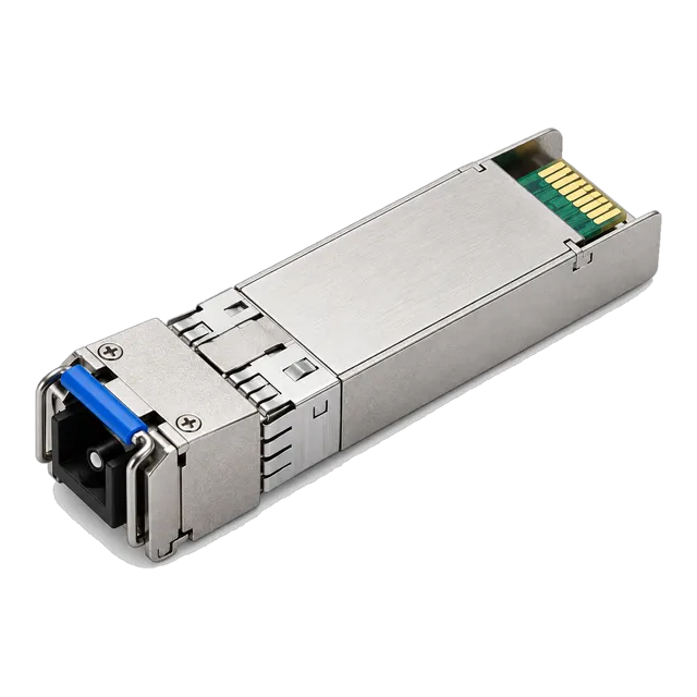
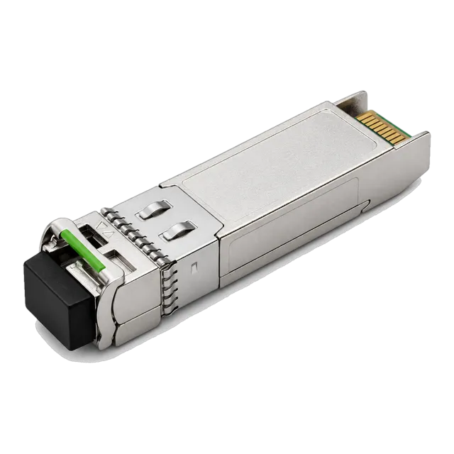
The SFP 10G LR transceiver delivers 10.3125 Gb/s over 10 km of OS2 single-mode fibre using a 1310 nm DFB laser, providing an optical power budget of 6.2 dB under IEEE 802.3ae Clause 52.
01What is an SFP 10G LR optical transceiver?
An sfp 10g lr is a hot-pluggable Small Form Factor Pluggable Plus (SFP+) optical transceiver designed for 10 Gigabit Ethernet (10GbE) long-reach data communications over single-mode fibre (SMF). Operating at a nominal line rate of 10.3125 Gb/s, this 10G SFP+ optical module conforms to the IEEE 802.3ae Clause 52 10GBASE-LR standard. The 'LR' designation denotes 'Long Reach', signifying a standardized operational distance of up to 10 kilometres across standard ITU-T G.652 single-mode optical core.
Unlike short-wavelength multimode modules, a 10gbase lr sfp transceiver uses a 1310 nm Distributed Feedback (DFB) laser transmitter paired with a high-sensitivity Positive-Intrinsic-Negative (PIN) photodiode receiver. This configuration enables high-speed data transmission across campus backbones, metropolitan area networks (MANs), and enterprise data centre inter-switch connections without experiencing the modal dispersion limits inherent to multimode fibre. The optical interface uses a standard duplex LC receptacle conforming to the IEC 61754-20 mechanical interface standard, while the host-side 20-pin card-edge connector satisfies the SFF-8431 electrical specification.
02SFP 10G LR: core optical specifications
The optical characteristics of the sfp 10g lr module are strictly governed by IEEE 802.3ae Clause 52 Table 52-12 and Table 52-13. The transmitter operates across a spectral window of 1260 nm to 1355 nm, centred at 1310 nm, with a maximum root-mean-square (RMS) spectral width of 1 nm and a side-mode suppression ratio (SMSR) of at least 30 dB. This narrow spectral linewidth minimizes chromatic dispersion along standard single-mode links.
| Optical Parameter | IEEE 802.3ae Specification | Typical MARS Production Unit | Engineering Unit |
|---|---|---|---|
| Transmitter Centre Wavelength | 1260 to 1355 | 1290 to 1330 | nm |
| Average Launch Power (Max) | +0.5 | -0.5 | dBm |
| Average Launch Power (Min) | -8.2 | -5.5 | dBm |
| Optical Extinction Ratio (Min) | 3.5 | 4.5 | dB |
| Receiver Sensitivity (Max / Worst-case) | -14.4 | -15.5 | dBm |
| Receiver Overload / Saturation (Min) | +0.5 | -0.5 | dBm |
| Receiver Wavelength Range | 1260 to 1355 | 1260 to 1355 | nm |
| Optical Return Loss Tolerance (Min) | 12.0 | 14.0 | dB |
A compliant 10gbase lr sfp module provides a guaranteed minimum channel insertion loss budget of 6.2 dB. This optical margin is calculated by subtracting the worst-case receiver sensitivity of -14.4 dBm from the minimum optical launch power of -8.2 dBm, before accounting for transmitter dispersion penalty (TDP) allocations specified in the IEEE 802.3ae framework.
03SFP 10G LR vs 10GBASE-SR: key technical differences
The fundamental difference between 10GBASE-LR and 10GBASE-SR is the transmission medium: LR operates across single-mode fibre at 1310 nm, whereas SR operates across multimode fibre (MMF) at 850 nm. When reviewing an SFP 10G SR transceiver guide, you will observe that SR transceivers use low-cost Vertical-Cavity Surface-Emitting Lasers (VCSELs) restricted by modal dispersion to reaches between 300 m on OM3 and 400 m on OM4.
| Metric | 10GBASE-LR (SMF) | 10GBASE-SR (MMF) |
|---|---|---|
| Laser Type | 1310 nm DFB Laser | 850 nm VCSEL |
| Fibre Core Diameter | 9 µm (ITU-T G.652 / G.657) | 50 µm (OM3 / OM4 / OM5) |
| Maximum Standard Reach | 10 km | 300 m (OM3) / 400 m (OM4) |
| Standard Attenuation Rate | 0.35 dB/km @ 1310 nm | 3.0 dB/km @ 850 nm |
| Dispersion Limiting Factor | Chromatic Dispersion | Modal Dispersion (Differential Mode Delay) |
| Module Power Consumption | 0.8 W to 1.2 W | 0.6 W to 0.9 W |
| Typical Deployment Space | Campus, Inter-building, Core rings | Intra-rack, Inter-rack within data halls |
While multimode optics historically offered lower transceiver costs, an lr sfp module eliminates the distance barriers of multimode cabling. It allows network architects to consolidate their physical infrastructure onto OS2 single-mode fibre, standardising testing procedures and cabling plant maintenance across an entire campus or metropolitan facility.
04Single-mode fiber compatibility: OS1 versus OS2 performance
A 10gbase lr sfp requires standard 9/125 µm single-mode optical fibre, but performance varies substantially between legacy OS1 indoor cable and modern OS2 outdoor or universal cable. Cable characteristics defined under ISO/IEC 11801 and ITU-T recommendations directly dictate the maximum operational link length and link margin at 1310 nm.
OS1 cable, defined primarily under ITU-T G.652.A and G.652.B, exhibits maximum attenuation of up to 1.0 dB/km at 1310 nm due to tight-buffered indoor construction and potential water-peak absorption. In contrast, OS2 cable compliant with ITU-T G.652.D (low water-peak non-dispersion-shifted fibre) or bend-insensitive ITU-T G.657.A1/A2 specifications features attenuation rates between 0.32 dB/km and 0.38 dB/km at 1310 nm. Review our guide on single-mode fiber cable and optical transceivers for deeper insights into core geometry.
When deploying an sfp lr module on legacy OS1, a 10 km run is mathematically unachievable because cable attenuation alone consumes 10.0 dB, well beyond the 6.2 dB optical budget. On OS2 infrastructure, 10 km of fibre induces only 3.5 dB of attenuation, leaving 2.7 dB for optical patch panels, splices, and environmental ageing degradation.
05Worked optical link budget calculation for a 10 km span
A reliable optical link budget calculation confirms whether an optical transceiver provides sufficient optical power to overcome all path attenuation while maintaining the required bit error ratio (BER) of 10⁻¹² without receiver saturation. Engineers can model these parameters using our interactive optical link budget calculator to verify transmission margins.
Consider an enterprise campus link across a 9.2 km run of ITU-T G.652.D OS2 fibre containing two intermediate cross-connect patch panels (four mated LC connector pairs) and six fusion splices. We calculate the link margin using worst-case IEEE 802.3ae parameters:
- Transceiver Parameters: Minimum Tx Launch Power = -8.2 dBm; Maximum Receiver Sensitivity = -14.4 dBm.
- Total Available Power Budget: (-8.2 dBm) - (-14.4 dBm) = 6.20 dB.
- Cable Attenuation: 9.2 km × 0.35 dB/km (nominal at 1310 nm) = 3.22 dB.
- Connector Insertion Loss: 4 mated LC/UPC pairs × 0.30 dB/pair (IEC 61753 Grade C) = 1.20 dB.
- Splice Insertion Loss: 6 fusion splices × 0.05 dB/splice = 0.30 dB.
- Total Channel Insertion Loss: 3.22 dB + 1.20 dB + 0.30 dB = 4.72 dB.
- Power Margin Calculation: Available Budget (6.20 dB) - Channel Insertion Loss (4.72 dB) = 1.48 dB.
An optical power margin of 1.48 dB remains. For critical infrastructure, industry standard practice mandates an unallocated safety margin of at least 1.5 dB to 2.0 dB to account for cable repair splices, transmitter thermal ageing, and connector contamination over time. If your calculated margin is tight, refer to our detailed analysis in why a 20 km module may not reach 20 km for troubleshooting dispersion and margin limits.
06Why overload matters: do you need an optical attenuator on short links?
An optical attenuator is generally not required for standard 10gbase lr transceivers deployed on short patch cords, provided the modules adhere strictly to the IEEE 802.3ae maximum launch power ceiling. The standard defines the maximum average launch power for 10GBASE-LR at +0.5 dBm, while the receiver overload point is also specified at +0.5 dBm.
Because the maximum transmitter launch power does not exceed the maximum optical input power handling capability of the PIN receiver, a zero-distance back-to-back connection with a 1-metre duplex LC single-mode patch lead will not destroy or burn out the photodiode. This contrasts sharply with extended-reach optics such as 10GBASE-ER or 10GBASE-ZR, which use avalanche photodiodes (APDs) that suffer irreversible damage when exposed to optical powers exceeding -1.0 dBm without inline attenuation.
However, during lab bench testing, transceivers operating near their maximum optical output (+0.5 dBm) can drive the PIN photodiode into non-linear optical saturation. Saturation causes pulse clipping, baseline wander, and localized bit errors even when no physical damage occurs. When conducting switch-to-switch testing across short patch cables under 50 metres, inserting a fixed 3 dB or 5 dB LC optical attenuator keeps the receiver operating within its linear dynamic range (-5 dBm to -10 dBm) and prevents transient link flap.
07How digital diagnostic monitoring operates in a 10GBASE-LR SFP module
Digital Diagnostic Monitoring (DDM), also referred to as Digital Optical Monitoring (DOM), allows network operators to interrogate the real-time operational parameters of the optical module via an I2C serial bus. The internal microcontroller reports telemetry stored in an internal 256-byte memory map defined by the SFF-8472 specification at I2C address 0xA2.
Engineers can review our guide on what DDM can tell you about an optical link to interpret these registers. The transceiver continuously measures five internal analog operating parameters:
- Transceiver Temperature: Internally measured temperature (-40°C to +85°C) calibrated to within ±3°C.
- Supply Voltage: Module operating voltage, typically 3.3 V with a valid tolerance band of ±5% (3.135 V to 3.465 V).
- Laser Bias Current: DFB laser drive current in milliamperes (mA). A rising bias current over time indicates laser diode ageing and imminent end-of-life.
- Transmitter Optical Output Power: Real-time optical launch power coupled into the fibre core, calibrated in microwatts (µW) and converted to dBm by the host switch CLI.
- Receiver Optical Input Power: Real-time received optical power reading from the PIN photodiode.
The SFF-8472 memory map contains factory-calibrated high alarm, high warning, low warning, and low alarm thresholds for each parameter. When the optical link degrades below -14.4 dBm, the transceiver triggers an interrupt pin on the host switch, initiating SNMP traps or Syslog alerts before service interruption occurs.
08Form factor architecture: SFP+ electrical interface and SFF-8431 compliance
The physical and electrical interface of an sfp 10g lr module conforms strictly to SFF-8431 (Enhanced Small Form Factor Pluggable Module SFP+) and SFF-8432 (Improved Pluggable Formfactor). The electrical interface utilizes a 20-pin card-edge connector carrying differential transmit and receive serial data signals (SFI electrical specification) running at 10.3125 Gb/s with 64b/66b line coding.
The module operates from a single +3.3 V power supply rail. Power consumption is categorized into Power Levels under SFF-8431: a standard commercial temperature 10gbase lr sfp module typically consumes between 0.8 W and 1.0 W, easily complying with Power Level 1 (<1.0 W) or Power Level 2 (<1.5 W) limits. This low power consumption enables high port density on 48-port top-of-rack (ToR) and core switches without overwhelming power supply units or chassis thermal management systems.
Host boards provide AC-coupling capacitors on high-speed differential signal pairs. The module's internal Clock and Data Recovery (CDR) circuitry reshapes and retimes incoming electrical signals from the host SerDes, mitigating inter-symbol interference (ISI) across the host printed circuit board (PCB) traces before electro-optical conversion.
09Comparing SFP 10G LR with BiDi, ER, and ZR variants
When link distances exceed 10 km, or when single-strand fibre conservation is mandatory, network designers must select alternative 10G SFP+ form factors beyond standard dual-strand 10GBASE-LR. Optical reach and wavelength architecture dictate the selection of BiDi, ER, and ZR variants.
| Transceiver Variant | Fibre Strands | Nominal Wavelength (nm) | Receiver Type | Optical Budget (dB) | Max Reach (km) |
|---|---|---|---|---|---|
| 10GBASE-LR | 2 (Duplex) | 1310 | PIN | 6.2 | 10 |
| 10G BiDi BX60 | 1 (Simplex) | 1270-Tx / 1330-Rx (or vice versa) | APD | 15.0 | 60 |
| 10GBASE-ER | 2 (Duplex) | 1550 | PIN / APD | 15.0 | 40 |
| 10G BiDi BX100 | 1 (Simplex) | 1490-Tx / 1550-Rx (or vice versa) | APD | 24.0 | 100 |
| 10GBASE-ZR | 2 (Duplex) | 1550 | APD | 24.0 | 80 |
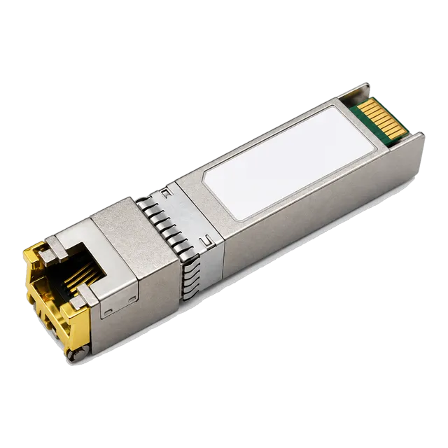
Where fibre lease costs are critical, single-fibre bidirectional optics provide double the data capacity per strand. Integrators deploying single-fibre paths can examine the 10G SFP+ BiDi BX60 60km Transceiver for mid-haul links or the carrier-grade 10G SFP+ BiDi BX100 100km Module for extreme long-haul spans. For short copper rack links under 100 metres where Cat6a cabling already exists, a 10G SFP+ Copper RJ45 Transceiver provides an alternative electrical interface.
10Host platform coding and EEPROM compatibility rules
Host equipment compatibility is determined by the configuration of the internal Electrically Erasable Programmable Read-Only Memory (EEPROM) governed by SFF-8024 and SFF-8472 at I2C address 0xA0. Switch operating systems interrogate these non-volatile memory registers upon module insertion to verify vendor identifiers, serial numbers, part numbers, and checksums.
Many tier-one host switches enforce vendor-locking mechanisms by default. If the 3-byte Vendor OUI (Organizationally Unique Identifier), vendor name string, or cyclic redundancy check (CRC) at byte 63 or byte 95 does not match the host manufacturer's internal database, the port is disabled or placed into an 'err-disabled / unsupported transceiver' state. Our technical overview on how transceiver coding works and EEPROM compatibility details the specific bit structures used across vendor operating systems.
MARS manufactures optical transceivers with custom-coded EEPROM maps tailored specifically to your switch environment. A fully coded 10gbase lr sfp transceiver passes all vendor hardware identification checks, reporting correct transceiver type, wavelength, and full DDM telemetry directly within the native host command-line interface (CLI) without requiring software bypass commands.
11Commercial versus industrial temperature ratings for outdoor deployments
Operating temperature ratings represent a primary differentiator when procuring an sfp 10g lr for outdoor plant cabinets, cell site routers, or trackside enclosures versus controlled enterprise data centres. Standard commercial-grade modules cannot survive the thermal extremes of unconditioned environments.
Commercial temperature (C-Temp) optics are rated for operation from 0°C to +70°C (32°F to 158°F). Industrial temperature (I-Temp) optics are rated from -40°C to +85°C (-40°F to 185°F). In a non-climate-controlled roadside cabinet, ambient summer temperatures reaching 45°C combine with host switch heat dissipation to drive internal chassis temperatures above 75°C.
As semiconductor temperature rises, laser performance shifts. The emission wavelength of an uncooled DFB laser drifts at a rate of approximately 0.08 nm/°C to 0.1 nm/°C due to thermal expansion of the laser cavity and changes in refractive index. Operating a C-Temp module at 80°C shifts the centre wavelength outside the 1260–1355 nm specification window, while threshold current escalates sharply, degrading optical output power and inducing packet dropouts. Industrial-grade transceivers incorporate hardened laser diodes, burn-in screening, and temperature-compensated drive electronics to guarantee stable optical power across the complete -40°C to +85°C span.
12Common link fault diagnosis and troubleshooting steps
Diagnosing an inactive or intermittent 10GBASE-LR connection requires a structured, multi-point verification process using physical inspection, CLI diagnostics, and optical power measurement tools. Network field engineers should execute the following five-step troubleshooting procedure:
- Inspect and Clean the Optical Endfaces: Contamination on the LC/UPC ferrule accounts for more than 75% of optical link failures. Inspect the connector using a 400x fibre scope and clean both the patch cord ferrule and the transceiver optical barrel using an IBC dry-cleaning click tool or lint-free optical wipes soaked in high-purity isopropyl alcohol.
- Verify Optical Polarity: Ensure the transmit (Tx) port on Switch A connects to the receive (Rx) port on Switch B. A simple visual check using a Visual Fault Locator (VFL) or examining patch cord crossover orientation resolves flipped polarity faults immediately.
- Query Host DDM Telemetry: Issue the host diagnostic command (such as
show interfaces transceiver detail) to read Rx optical power. If Rx power reads below -14.4 dBm (the receiver sensitivity threshold), the link loss exceeds the optical power budget. If Rx power reads below -30 dBm, the physical link is completely broken. - Validate Host Port Speed and Autonegotiation: SFP+ ports do not automatically negotiate speed between 1G and 10G on most enterprise platforms. Confirm that both switch ports are statically configured for 10 Gb/s operation and that forward error correction (FEC) settings match, if supported by the host.
- Conduct Local and Remote Optical Loopbacks: Insert an optical patch cord with a 5 dB attenuator directly connecting the module's Tx port to its Rx port. If the link LED illuminates and the port state transitions to 'up', the transceiver optics and host port hardware are fully functional, isolating the fault to the external structured cabling plant.
13Procurement checklist for engineering and purchasing teams
Engineering and procurement teams can eliminate compatibility and operational failures by issuing a rigorous, structured Request for Quotation (RFQ) checklist when sourcing optical transceivers. Sourcing teams should paste the following technical criteria directly into supplier tenders:
| Procurement Parameter | Required Technical Specification | Engineering Verification Standard |
|---|---|---|
| Data Rate & Protocol | 10.3125 Gb/s; 10GBASE-LR Ethernet | IEEE 802.3ae Clause 52 |
| Form Factor & Connector | SFP+ with Duplex LC Receptacle | SFF-8431, SFF-8432, IEC 61754-20 |
| Optical Centre Wavelength | 1260 nm to 1355 nm (Nominal 1310 nm) | DFB Single-Longitudinal Mode Laser |
| Optical Power Budget | Minimum 6.2 dB (Launch: -8.2 dBm; Sens: -14.4 dBm) | Class 1 Laser Safety (IEC 60825-1) |
| Digital Diagnostics | Full internal calibration (Temp, Vcc, Bias, Tx, Rx) | SFF-8472 Diagnostic Monitoring Interface |
| Operating Temperature Grade | Commercial (0 to 70°C) or Industrial (-40 to 85°C) | Deployment site thermal verification |
| Host Platform Compatibility | Pre-programmed EEPROM coded to target switch OS | SFF-8024 Vendor OUI validation |
| Compliance Standards | RoHS 6/6, CE, FCC Class B, WEEE | Environmental and electromagnetic compliance |
14Specifying and testing your 10GBASE-LR deployment
To ensure high link availability and error-free operation across enterprise and service provider networks, validate all link budget parameters prior to physical hardware installation. Network engineers should utilize our online link budget calculator to calculate insertion loss margins against real-world plant documentation.
For enterprise campus expansions, data centre aggregation upgrades, or custom host switch firmware coding requirements, contact the optical engineering team at Shanghai Mars Industrial Co., Ltd. through our contact page or directly via email at inquiry@optical-module-factory.com. Providing your host platform model numbers, operating switch OS versions, and optical fibre plant lengths enables our engineering laboratory to deliver fully validated, custom-coded, and 100% interoperable SFP 10G LR modules ready for immediate network deployment.
15Frequently asked questions
What is the maximum distance for an SFP 10G LR transceiver?
The maximum transmission distance for a standard SFP 10G LR transceiver is 10 kilometres (6.2 miles) over OS2 single-mode fibre. Operating distances beyond 10 km require extended-reach optics such as 10GBASE-ER (40 km) or 10GBASE-ZR (80 km).
Can I use an SFP 10G LR transceiver on multimode fiber?
Using SFP 10G LR on multimode fibre is not recommended and supports a maximum reach of approximately 220 metres using specialized mode-conditioning patch cords. Connecting a 1310 nm single-mode laser directly into 50 µm or 62.5 µm multimode core causes severe Differential Mode Delay, resulting in high bit error rates.
Do I need an optical attenuator with an SFP 10G LR module on short links?
No, an optical attenuator is generally not required for SFP 10G LR modules on short links. The maximum transmitter launch power (+0.5 dBm) does not exceed the receiver overload point (+0.5 dBm). However, using a 3 dB or 5 dB attenuator during bench testing stabilizes receiver saturation.
Is SFP 10G LR backward compatible with 1G SFP slots?
No, an SFP 10G LR transceiver will not operate in a standard 1G SFP slot. SFP+ slots can accept 1G SFP optics if supported by host software, but 10G SFP+ modules require 10G-capable host hardware and cannot auto-negotiate down to 1 Gb/s unless explicitly designed as dual-rate hardware.
What is the difference between 10GBASE-LR and 10GBASE-LW?
10GBASE-LR transmits 10 Gigabit Ethernet framing directly at 10.3125 Gb/s over single-mode fibre. 10GBASE-LW encapsulates Ethernet data within a SONET STS-192c / SDH STM-64 frame at a line rate of 9.953 Gb/s, allowing direct transport across legacy synchronous optical networks without intermediate mapping.
What is the wavelength of a 10GBASE-LR SFP+ module?
A 10GBASE-LR SFP+ module operates at a nominal optical wavelength of 1310 nm. Under IEEE 802.3ae Clause 52 standards, the permissible spectral transmission window spans from 1260 nm to 1355 nm using an uncooled Distributed Feedback (DFB) laser diode.
Technical review note: confirm model-specific specifications with the product datasheet and the intended host documentation. Product images and application photographs are illustrative.
Discuss this with our team