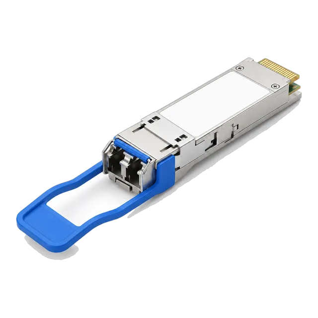
Parallel optics fail for structural reasons rather than optical ones: wrong polarity, wrong pinning, mixed Base-8 and Base-12 components, or a contaminated ferrule nobody inspected.
01Why parallel optics need a cabling method
A duplex link has one fiber going out and one coming back, and getting it wrong is obvious and easy to fix. Parallel optics are different. A 40GBASE-SR4 or 100GBASE-SR4 module transmits on four fibers and receives on four fibers simultaneously through a single multi-fiber connector, so the cabling system must deliver each of those eight fibers to the correct position at the far end, in the correct direction, through however many trunks, cassettes and patch cords sit in between.
That is what polarity methods exist to guarantee. They are not preferences; they are complete systems of components that only work when applied consistently end to end. Most parallel-optics faults in the field are not optical faults at all. They are a trunk, a cassette or a patch cord from a different method mixed into an otherwise correct channel.
02The connector: MPO, MTP, keys and ferrules
MPO is the generic multi-fiber push-on connector defined in international standards. MTP is a particular manufacturer's implementation of an MPO connector with tighter mechanical tolerances; it is intermateable with MPO, and the two terms are used interchangeably in catalogues. The connector holds fibers in a rectangular ferrule in rows of twelve, and a key on the body sets orientation.
Key orientation is the basis of polarity. Two MPO connectors mate in an adapter either key-up to key-down, which reverses nothing, or key-up to key-up, which reverses the fiber order across the ferrule. Positions are numbered from one to twelve looking into the ferrule with the key up. The catalogue modules that use this interface, such as the 40G QSFP+ SR4 and the 100G QSFP28-SR4 MPO-12 transceivers, list the connector simply as MPO or MTP, so the polarity system is entirely the responsibility of the cabling design.
03Which fibers a transceiver actually uses
In a twelve-fiber MPO interface, a 40G or 100G SR4 transceiver uses eight fibers and leaves four dark. Positions one to four carry the four transmit lanes, positions nine to twelve carry the four receive lanes, and positions five to eight in the middle are unused. Twenty-four-fiber MPO variants exist for higher-lane-count applications, but the four-lane modules that dominate 40G and 100G deployments need only eight fibers.
This is the origin of the Base-8 versus Base-12 debate. Building a parallel-optics channel from twelve-fiber components means a third of the installed fiber is never lit. That is acceptable when the same trunk also feeds duplex links through cassettes, and wasteful when the trunk exists purely to serve SR4 ports. Knowing which fibers the module uses also makes troubleshooting faster, because a fault in the middle four positions cannot be the cause of a dead SR4 link.
04Base-8 and Base-12 trunks
A Base-12 system is built from twelve-fiber increments: twelve-fiber trunks, twelve-fiber cassettes, twenty-four and forty-eight fiber trunks made of twelve-fiber groups. It is the older and still very common approach, and it converts neatly to duplex LC through six-port cassettes.
A Base-8 system is built from eight-fiber increments and maps one trunk group directly onto one four-lane parallel module with nothing left dark. For a data hall built primarily around SR4 and PSM4 links, Base-8 uses the installed fiber more efficiently and makes capacity planning simpler, because one trunk equals one 40G or 100G link. The two systems are not interchangeable at the component level. Mixing a Base-12 trunk with Base-8 breakout harnesses produces channels that appear to be connected and are not, so choose one system for a given fiber plant and hold to it.
05Polarity Method A
Method A uses a key-up to key-down trunk, meaning fiber position one at one end arrives at position one at the other. Because the trunk itself does not reverse anything, the reversal needed to connect a transmitter to a receiver is performed by the patch cords: one end of the channel uses an A-to-A type patch cord and the other end uses an A-to-B type, or equivalently the duplex LC pair is flipped at one end.
The strength of Method A is that it uses straight trunks, which are simple to manufacture and to extend. The weakness is operational: two different patch cord types exist in the channel, they look similar, and installing the wrong one at the wrong end is a quiet failure. If a site uses Method A, patch cords must be labelled clearly and stocked separately.
06Polarity Method B
Method B uses a key-up to key-up trunk, in which the fiber order is reversed across the ferrule: position one arrives at position twelve, position two at eleven, and so on. The trunk itself provides the crossover, so every patch cord in the channel is the same type and no flipping is required anywhere.
That uniformity is why Method B is the usual choice in data centres built around parallel optics. It removes the most common human error, because there is only one kind of patch cord on the shelf. The consideration to watch is single-mode APC connectors. Because the ferrule end faces are angled, a reversed Method B trunk must be built with the correct combination of male and female components and matching end-face geometry at every mating point, so an APC channel must be specified as a complete system rather than assembled from whatever is available.
07Polarity Method C
Method C uses a pair-flipped trunk, in which fibers are swapped in pairs: position one arrives at position two, position two at position one, three at four, and so on. It was designed for duplex applications, where flipping each transmit and receive pair inside the trunk delivers a correct duplex channel with identical patch cords at both ends.
Method C should not be used for parallel optics. An SR4 module needs four adjacent transmit lanes mapped to four adjacent receive lanes at the far end, and a pair-flipped trunk scrambles that mapping. This is a frequent cause of failure in mixed estates: a pair-flipped trunk installed years ago for duplex 1G or 10G links still works perfectly for those links, and every 40G or 100G port added to it fails. If a site has legacy Method C trunking, record it clearly before anyone plans parallel optics over it.
08Pinned and unpinned connectors
MPO connectors are either pinned, with two alignment pins protruding from the ferrule, or unpinned. A mated pair must consist of exactly one pinned and one unpinned connector. Two unpinned connectors will not align, and two pinned connectors cannot mate at all and risk damaging the ferrules.
The standard convention is that trunk cable ends are unpinned and the patch cords or cassette ports that mate with them are pinned, but conventions vary between manufacturers and between projects. The transceiver's own MPO receptacle is pinned, so the patch cord that plugs into the module must be unpinned. Every MPO order should state pinning explicitly for each end. A shipment of correct-length, correct-polarity trunks that are pinned the wrong way is useless on the day of installation and is one of the more expensive avoidable mistakes.
09Cassettes, harnesses and conversion modules
Cassettes convert an MPO trunk into duplex LC ports, allowing one multi-fiber trunk to feed several duplex links; a twelve-fiber cassette typically presents six LC duplex ports. Breakout harnesses do the opposite job for parallel optics used in breakout mode, splitting one MPO into four duplex LC pairs so that a 40G or 100G port can serve four independent links terminated in SFP+ or SFP28 modules.
Conversion modules exist to bridge Base-12 trunks and Base-8 applications, taking three twelve-fiber inputs and presenting four eight-fiber outputs. They solve a real problem but add mated pairs to the channel, and mated pairs consume the very small insertion loss budget that short-reach parallel links allow. Every cassette or conversion module in the path should be counted in the loss calculation before it is installed, not afterwards.
10Loss budget: why MPO channels run out of headroom
Short-reach parallel links have little loss to spare. The channel insertion loss allowed for 40G and 100G SR4 variants is on the order of one and a half to two decibels in total, against a fiber attenuation of only a few tenths of a decibel over the permitted distance. Almost the entire budget is spent on connections.
An MPO mated pair typically contributes several tenths of a decibel, and a cassette contains one MPO mating and one LC mating. A channel with two cassettes and two patch cords at each end can therefore consume most of the allowance before the fiber is considered. Two disciplines follow. First, count every mated pair in the design and compare the total against the standard's figure for the variant in use. Second, test the installed channel with an encircled flux compliant source rather than assuming the design figures were achieved.
11Inspection and cleaning
A single-fiber LC connector concentrates the risk of contamination on one core. An MPO ferrule presents twelve or twenty-four cores on a wide flat surface that is easy to touch, easy to lay on a bench and hard to inspect without the right tool. Contamination is the leading cause of high-loss parallel channels.
The discipline is straightforward. Inspect every ferrule with an MPO-capable video inspection probe before every mating, because a connector that was clean last month is not necessarily clean now. Clean with a cleaner designed for multi-fiber ferrules rather than a single-fiber tool or a wipe. Inspect again after cleaning to confirm the result. Keep dust caps on every unmated connector and adapter at all times, including during a break in work. Never mate a connector that has not been inspected; mating dirt transfers it to the other ferrule and turns one cleaning job into two.
12Field mistakes and how to prevent them
The recurring faults are consistent across sites. Mixing polarity methods within one channel. Installing a pair-flipped Method C trunk under parallel optics. Ordering trunks with the wrong pinning. Combining Base-8 harnesses with Base-12 trunks. Exceeding the loss budget by adding a cassette pair to an already long channel. Mating a contaminated ferrule. Exceeding the bend radius when routing a stiff trunk into a crowded cabinet, which stresses the outer fiber positions first and produces a link that fails on some lanes and not others.
Prevention is documentation. Record the polarity method, the base, the pinning convention and the connector end-face type for the whole facility, keep the record where installers will see it, and specify all four in every order.
13Frequently asked questions
What is the difference between MPO and MTP?
MPO is the generic multi-fiber push-on connector defined in international standards. MTP is a specific manufacturer's version of an MPO connector built to tighter mechanical tolerances. They are intermateable and catalogues often write MPO/MTP as a single connector designation, so the practical difference in an order is the component brand rather than the interface.
Which polarity method should I use for 40G and 100G?
Method B is the usual choice for parallel optics, because the trunk provides the crossover and every patch cord in the channel is the same type, which removes the most common installation error. Method A works but requires two different patch cord types. Method C is pair-flipped and must not be used for parallel optics, although it may be present on legacy duplex trunks.
What is the difference between Base-8 and Base-12 cabling?
Base-12 builds the plant in twelve-fiber increments, which suits cassettes feeding duplex LC links but leaves four fibers dark on every four-lane parallel module. Base-8 builds in eight-fiber increments so one trunk group maps exactly to one 40G or 100G SR4 link. The systems are not interchangeable, so choose one per fiber plant and stay with it.
Why must one MPO connector be pinned and the other unpinned?
The two alignment pins hold the ferrules in precise register while they mate. A pinned connector must therefore meet an unpinned one. Two unpinned connectors cannot align accurately, and two pinned connectors cannot mate and may damage the ferrules. Transceiver receptacles are pinned, so the patch cord entering a module must be unpinned. Always state pinning for each end when ordering.
How should MPO ferrules be cleaned?
Inspect first with an MPO-capable video probe, clean with a tool designed for multi-fiber ferrules rather than a single-fiber cleaner or a wipe, then inspect again to confirm. Repeat before every mating, keep dust caps fitted whenever a connector or adapter is unmated, and never mate a ferrule that has not been inspected, since contamination transfers to the mating connector.
Technical review note: confirm model-specific specifications with the product datasheet and the intended host documentation. Product images and application photographs are illustrative.
Discuss this with our team