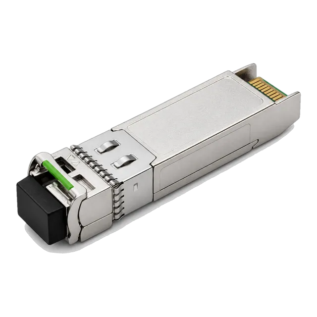
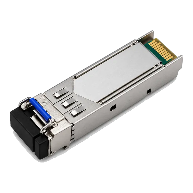
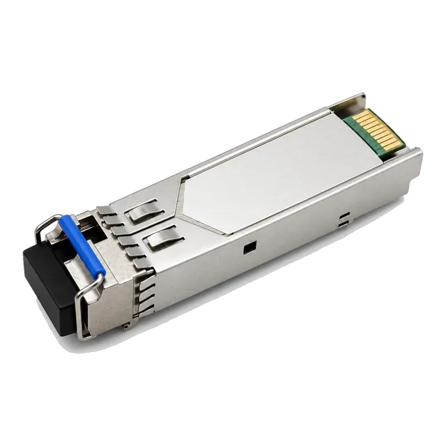
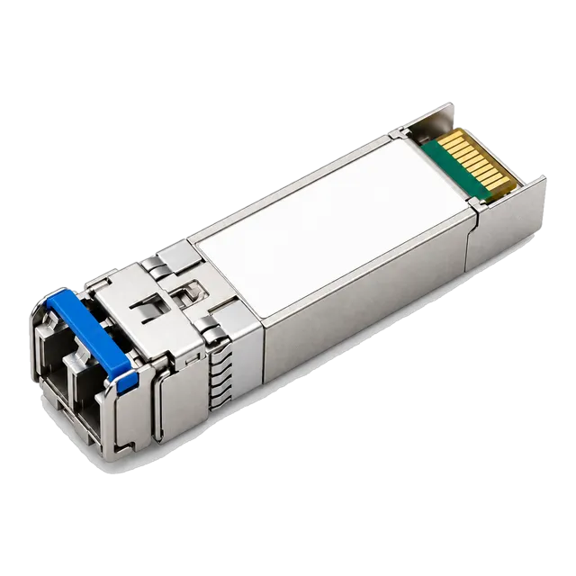
The single mode fiber LC connector delivers high-density optical termination using a 1.25 mm ferrule, requiring sub-micron concentricity, strict IEC 61300-3-35 end-face cleanliness, and disciplined return loss specification to preserve link budgets in high-speed networks.
01What is a single mode fiber LC connector?
A single mode fiber lc connector is a small form factor optical interconnect terminating 9/125 µm single-mode optical fibre within a precision 1.25 mm zirconia ceramic ferrule. Developed by a major telecommunications manufacturer and standardised internationally under IEC 61754-20 and TIA-604-10 (FOCIS-10), the connector uses an RJ45-style audible latching mechanism that prevents accidental disconnection under axial load.
In telecommunication central offices, enterprise data centres, and metropolitan optical transport platforms, the connector aligns the micron-scale optical core of an ITU-T G.652.D or G.657.A1 single-mode fibre with the optical sub-assembly of transceivers or adjacent patch cables. Because a single-mode core measures only 8.2 to 9.2 µm in mode field diameter (MFD) at 1310 nm, the connector ferrule must maintain bore runout and concentricity under 0.5 µm to prevent significant lateral misalignment loss. For complete network infrastructure design, engineers evaluate both the connector physical interface and the underlying glass, as detailed in our Single Mode Fiber Cable and Optical Transceiver Guide.
02Single mode fiber lc connector dimensions and mechanical standards
Standard single mode fiber lc connector interfaces conform strictly to the mechanical dimensions established in IEC 61754-20 to ensure intermateability across physical layer manufacturers.
The outer diameter of the cylindrical ceramic ferrule is 1.249 mm with a tolerance of ±0.0005 mm (0.5 µm). The connector housing features an overall width of 6.25 mm and a height of 9.4 mm, which precisely halved the spatial footprint of earlier 2.5 mm legacy connectors such as SC and FC. This compact profile enabled the standard 19-inch rack unit (1RU) patch panel density to jump from 24 duplex ports up to 48 or 96 duplex LC ports.
Mechanically, the internal spring mechanism provides an axial contact force of between 4.9 N and 7.8 N against the opposing ferrule inside a split alignment sleeve. The latch disengagement mechanism requires a minimum tensile pull-proof resistance of 100 N on reinforced jacketed patch leads, ensuring that cable tension within raceways does not shift the optical end-face contact plane.
03LC/UPC versus LC/APC: geometry, optical return loss, and colour codes
The distinction between Ultra Physical Contact (UPC) and Angled Physical Contact (APC) lies in the end-face geometry of the ceramic ferrule, which directly governs optical return loss (ORL).
An LC/UPC connector features a slightly domed end-face polished perpendicular (0 degrees) to the fibre axis. Any optical power reflected back at the glass-to-glass interface travels straight into the laser cavity, yielding a standard return loss of −50 dB to −55 dB. LC/UPC housings and strain-relief boots are industry-standardised in blue.
An LC/APC connector polishes the ferrule end-face at an 8-degree angle. This slant deflects back-reflected optical energy out into the glass cladding rather than along the core, achieving return loss values exceeding −60 dB to −65 dB. LC/APC connectors use green housings and boots. Never mate an LC/UPC connector with an LC/APC connector. Doing so introduces an angled physical gap that causes catastrophic insertion loss greater than 4.0 dB and permanently deforms the ceramic ferrule end-faces through uneven mechanical pressure.
04Insertion loss and return loss specifications for single-mode LC interfaces
Optical transmission budgets require connectors to meet rigorous optical attenuation and reflectance performance grades as defined by IEC 61753-1.
Random mating insertion loss (IL) measures the attenuation introduced when two randomly selected connectors are joined through a split sleeve. Optical return loss (ORL) quantifies the ratio of launched power to reflected power. The following table outlines the international performance grades specified for single-mode LC interfaces:
| IEC 61753-1 Grade | Mean Insertion Loss (dB) | Max Insertion Loss 97% (dB) | Return Loss Standard (dB) | Typical Industry Application |
|---|---|---|---|---|
| Grade A (Ultra-grade) | ≤ 0.07 | ≤ 0.15 | ≥ 60 (APC) / ≥ 50 (UPC) | Reference leads, test laboratory standards |
| Grade B (High-performance) | ≤ 0.12 | ≤ 0.25 | ≥ 60 (APC) / ≥ 50 (UPC) | Hyperscale backbones, DWDM transport |
| Grade C (Standard telecom) | ≤ 0.25 | ≤ 0.50 | ≥ 60 (APC) / ≥ 50 (UPC) | Enterprise LAN, standard data centre patching |
| Grade D (Commercial) | ≤ 0.50 | ≤ 0.75 | ≥ 45 (UPC) | Non-critical legacy low-speed campus links |
When calculating optical power budgets, network designers typically budget 0.30 dB to 0.50 dB per mated LC pair to absorb field tolerances, minor contamination, and connector mechanical fatigue over time.
05Simplex LC vs duplex LC in fiber optic transceivers
Duplex LC configurations use two joined connectors for simultaneous transmit (Tx) and receive (Rx) over two dedicated fibres, whereas simplex LC configurations combine both directions onto one single fibre.
Standard transceivers for dual-fibre links—such as our 25G SFP28 ZR 1310nm 80km Single-Mode Duplex LC Long-Reach module—use a duplex LC receptacle. One optical port couples light into the outbound single-mode core, while the adjacent port receives the incoming signal. Polarity maintenance across duplex cabling ensures that Tx at switch Node A lands on Rx at switch Node B.
Conversely, bidirectional (BiDi) optics utilise a simplex LC connector receptacle. The transceiver integrates an internal wavelength-division multiplexing (WDM) diplexer or triplexer filter that splits inbound and outbound optical channels operating on separated wavelengths—such as 1270 nm and 1330 nm—through the same physical LC ferrule. Simplex LC deployments immediately halve the required physical fibre count across long-distance cable routes.
06Fiber optic cable LC connector termination: factory pre-terminated versus field assembly
Factory-terminated LC assemblies yield significantly higher optical performance and structural longevity than manual field-installed connectors.
Automated factory termination injects heat-curing epoxy into the ferrule cavity, followed by multi-stage robotic diamond-film polishing. This process guarantees ferrule end-face geometry metrics mandated by IEC 61755-3-1: radius of curvature between 10 and 25 mm, apex offset under 50 µm, and fibre protrusion/undercut between −50 nm and +50 nm.
Field assembly methods fall into two categories:
- Splice-on Connectors (SOC): An LC connector with a factory-cleaved, factory-polished internal pigtail is fusion-spliced directly to the field fibre inside a specialised fusion splicer. This yields factory-grade optical loss (typically 0.15 dB) and excellent return loss without chemical handling.
- Mechanical Splice Connectors: The stripped field fibre is cleaved and shoved into an internal mechanical cam containing index-matching gel against an internal stub. While rapid for emergency restorations, mechanical LC terminations exhibit higher insertion losses (0.3 dB to 0.75 dB) and the index-matching gel can degrade over thermal cycles.
07Optical transceivers with simplex LC interfaces
Transceivers designed with simplex LC receptacles enable single-strand bidirectional communication, maximising physical plant utilization in fiber-constrained environments.
In telecommunication transport and 5G mobile fronthaul, simplex LC optical transceivers operate in complementary matched pairs. For example, our carrier-grade 10G SFP+ BiDi BX60 60km 1270/1330nm Transceiver houses a simplex LC port using an internal optical diplexer: one terminal transmits at 1270 nm and receives at 1330 nm, while the opposite end transmits at 1330 nm and receives at 1270 nm.
For higher bandwidth deployments, the 25GBASE-BR20 SFP28 BiDi Single-Fiber 1270/1330nm 20km WDM module uses the same simplex LC single mode interface to run 25 Gb/s Ethernet links over single-mode lines. When deploying lower speed edge networks, legacy devices rely on the 1.25G BiDi Single-Fiber SFP Transceiver 1310nm/1550nm 20km. To review operational wavelength pairings across carrier networks, refer to our BiDi Transceiver Engineering Guide.
08Cleaning and inspection standards: IEC 61300-3-35 compliance
End-face contamination is the primary cause of link degradation, insertion loss spikes, and transceiver optical sub-assembly damage in single-mode systems.
IEC 61300-3-35 defines automated visual pass/fail criteria across four concentric zones on a 1.25 mm single mode fiber lc connector ferrule:
- Zone A (Core, 0 to 25 µm diameter): No scratches or defects are permitted. Even a sub-micron dust speck on the core blocks light and generates severe backreflections.
- Zone B (Cladding, 25 to 115 µm diameter): Scratches up to 3 µm width are acceptable; no loose debris or pits larger than 2 µm permitted.
- Zone C (Adhesive layer, 115 to 125 µm diameter): Minor bonding adhesive anomalies acceptable provided they do not migrate inward.
- Zone D (Contact ferrule surface, 125 to 250 µm diameter): Defects up to 10 µm permitted, provided they do not prevent physical glass contact.
Cleaners must deploy dry-cleaning mechanical push-pens or lint-free micro-fibre cassettes. If oil or fluid residue persists, employ wet-to-dry cleaning using high-purity optical solvents (>99% optical-grade isopropyl alcohol or fluorinated hydrocarbon solvents), followed immediately by a certified video inspection probe.
09Worked link budget calculation: 10G BiDi link with single-mode LC patch fields
A practical link budget calculation confirms whether an optical transceiver has sufficient optical power to bridge physical fiber spans and mated LC patch panels without exceeding bit error rate thresholds.
Consider an enterprise campus connecting two data centres over a 30 km outside plant (OSP) single-mode G.652.D fibre run. The link uses our 10G SFP+ BiDi BX60 60km 1270/1330nm Transceiver terminating through simplex LC patch panels.
- Optical Transmitter Power: Minimum Launch Power (P_min) = +1.0 dBm
- Receiver Sensitivity: Minimum Sensitivity (P_sens) = −20.0 dBm
- Available Power Budget: P_budget = P_min − P_sens = +1.0 dBm − (−20.0 dBm) = 21.0 dB
Next, we sum the cumulative passive insertion losses across the 30 km channel operating at the worst-case wavelength of 1270 nm:
- Fibre attenuation at 1270 nm: 30 km × 0.38 dB/km = 11.4 dB
- Mated LC connector pairs: 4 interconnect locations (Tx panel, Rx panel, 2 OSP patch bays) × 0.35 dB/connector = 1.4 dB
- Fusion splices along cable route: 6 splices × 0.05 dB/splice = 0.3 dB
- Transmitter dispersion penalty (10 Gb/s at 1270 nm over 30 km): 1.5 dB
- Total Channel Loss: 11.4 + 1.4 + 0.3 + 1.5 = 14.6 dB
Finally, we calculate the remaining unallocated link margin:
Link Margin: 21.0 dB (Available Budget) − 14.6 dB (Total Channel Loss) = 6.4 dB.
A link margin of 6.4 dB comfortably surpasses the standard carrier safety margin of 3.0 dB, ensuring reliable operation across laser ageing, temperature swings, and minor patch cable bends. For custom distance calculations, try our interactive Optical Link Budget Calculator.
10Polarity management in single-mode duplex LC cabling
Polarity management guarantees that the optical transmitter on one network node maps seamlessly to the optical receiver of the complementary node across duplex LC infrastructure.
TIA-568.3-D standardises three primary duplex wiring schemes:
- Method A (Straight-through): Utilises Method A trunk cables (pin 1 to pin 1) with an A-to-B patch cord on one end and an A-to-A patch cord on the opposite end to perform the crossover.
- Method B (Reversed): Utilises cross-over trunks (pin 1 to pin 12, pin 2 to pin 11) with standard A-to-B patch leads at both terminal ends.
- Method C (Pair-flipped): Employs individual pair twists within trunk segments, maintaining standard A-to-B patching throughout.
For field modifications, modern duplex LC patch cables feature removable clips or uniboot housings. Technicians can release the outer clip and swap the positions of the A and B ferrule bodies without cutting or re-terminating the glass, instantly converting a straight patch lead into a crossover assembly.
11Single-mode LC connector troubleshooting and failure modes
Systematic physical-layer troubleshooting identifies whether optical link drops stem from connector mechanical damage, ferrule end-face contamination, or lateral misalignment.
Common failure modes and diagnostic procedures include:
- Optical Return Loss Spikes: High backreflections register on optical time-domain reflectometers (OTDR) as sharp reflective spikes exceeding −40 dB on a UPC link. This typically signifies an air gap between ferrules caused by particulate matter or a mismatched UPC-to-APC connection.
- High Insertion Loss with Low Backreflection: An OTDR shows a non-reflective step-loss drop greater than 1.0 dB. The cause is usually extreme core eccentricity, an internal fibre fracture within the strain-relief boot, or severe macro-bending of the patch lead.
- Transceiver Port Instability (Relative Intensity Noise): Contaminated LC connectors plugged directly into distributed feedback (DFB) laser transceivers reflect light straight into the laser cavity. This induces laser mode hopping, leading to intermittent bit errors and CRC packet discards.
- Intermittent Latch Release: Deformed or cracked plastic latch arms fail to sustain the 4.9 N spring contact force inside the receptacle, allowing building vibrations to momentarily separate the physical glass interface.
12Comparing LC with SC, FC, and MPO connectors in optical networks
Selecting the optimal connector format requires balancing port density, insertion loss characteristics, optical return loss, and mechanical latching stability across different network tiers.
The table below compares the single mode fiber lc connector with alternative optical interfaces widely found across modern and legacy network architectures:
| Connector Type | Ferrule Diameter (mm) | Standard Polish Grades | Typical 1RU Patch Density | Primary Network Application |
|---|---|---|---|---|
| LC | 1.249 mm | UPC (−50 dB), APC (−65 dB) | Up to 96 Duplex Ports (192 fibres) | Pluggable optical transceivers, high-density patch panels, carrier metro |
| SC | 2.499 mm | UPC (−50 dB), APC (−65 dB) | Up to 48 Simplex/Duplex Ports | PON FTTH drops, legacy 1G GBIC switches, optical test equipment |
| FC | 2.499 mm | UPC (−50 dB), APC (−65 dB) | Up to 24–48 Ports | Laboratory instrumentation, high-vibration maritime/industrial OSP |
| MPO | Rectangular (MT ferrule) | Flat PC (MMF), 8° APC (SMF) | Up to 144 Ports (Multi-fiber arrays) | QSFP-DD/OSFP transceivers, data centre spine-leaf trunking |
While MPO connectors lead multi-fibre parallel transmission at 400G and 800G, the single-mode LC remains the dominant individual port interface for transceivers up to 100G per wavelength.
13Procurement checklist for single mode fiber LC connector assemblies and transceivers
Procurement teams and optical network engineers should verify that their requests for quotation (RFQs) contain precise electrical, optical, and mechanical specifications.
When purchasing single mode fiber lc connector assemblies, patch panels, or simplex/duplex transceivers, ensure your bill of materials (BOM) specifies the following verifiable parameters:
- Fibre Glass Core Grade: Specify ITU-T G.652.D (low water peak) for standard data centre patch leads, or ITU-T G.657.A1/A2 (bend-insensitive, 7.5 mm minimum bend radius) for dense rack wiring.
- Ferrule Polish and Return Loss: Mandate LC/UPC (blue, ORL ≥ 50 dB) for standard Ethernet optics; mandate LC/APC (green, ORL ≥ 60 dB) for RF video, DWDM, and PON circuits.
- Maximum Insertion Loss Limits: Specify Grade B (IL ≤ 0.12 dB mean, ≤ 0.25 dB max) for core interconnects; Grade C (IL ≤ 0.25 dB mean, ≤ 0.50 dB max) for standard access patching.
- End-Face Geometry Inspection: Require factory 100% video interferometry reports conforming to IEC 61755-1 (Radius of curvature: 10–25 mm; Apex offset: < 50 µm; Fibre height: ±50 nm).
- Transceiver Connector Compatibility: Align the cable connector with the transceiver receptacle: duplex LC for dual-fibre optics, or simplex LC for single-fibre BiDi modules such as our 10G SFP+ BiDi BX60 and 25GBASE-BR20 SFP28 BiDi units.
- Jacket Fire Rating: Low Smoke Zero Halogen (LSZH) for UK/EU deployments; OFNP (Plenum) or OFNR (Riser) for North American building codes.
14Frequently asked questions
What is the core size of a single mode fiber LC connector?
A single mode fiber LC connector terminates standard 9/125 µm single-mode optical fibre. The mode field diameter of the light-carrying core measures approximately 8.2 to 9.2 µm at 1310 nm, enclosed within a 125 µm outer silica cladding.
Can you plug an LC/UPC connector into an LC/APC port?
No, you must never mate an LC/UPC connector into an LC/APC port. The 8-degree angled polish of the APC ferrule creates a direct air gap against the flat UPC end-face, causing insertion losses exceeding 4.0 dB and physical destruction of the polished ceramic tips.
What is the standard insertion loss for a single-mode LC connector?
Under IEC 61753-1 Grade B specifications, high-performance single-mode LC connectors deliver a mean insertion loss of ≤ 0.12 dB and a 97% maximum of ≤ 0.25 dB. Standard commercial Grade C connectors allow up to 0.50 dB per mated pair.
What is the difference between simplex LC and duplex LC connectors?
A duplex LC connector links two fibres side-by-side for simultaneous transmit and receive communication across two dedicated strands. A simplex LC connector terminates a single fibre, typically used with bidirectional (BiDi) transceivers that transmit and receive over separate wavelengths on one strand.
How do you clean a single mode fiber LC connector ferrule?
Inspect the ferrule end-face using a certified optical microscope probe conforming to IEC 61300-3-35. Clean using an optical dry-cleaning push pen. For persistent organic residue, use a wet-to-dry cleaning process with >99% optical-grade solvent followed immediately by dry micro-fibre wiping.
Why is the LC connector ferrule 1.25 mm instead of 2.5 mm?
The 1.25 mm zirconia ferrule was engineered by a major telecommunications manufacturer to cut the physical footprint of legacy 2.5 mm connectors (such as SC and ST) in half. This compact profile enables network equipment manufacturers to double port density across switches and patch panels.
Technical review note: confirm model-specific specifications with the product datasheet and the intended host documentation. Product images and application photographs are illustrative.
Discuss this with our team