Deploying a fiber to ethernet converter bridges the 100-metre copper distance barrier, provided engineers match transmission wavelengths, calculate optical power budgets with safe margins, and enforce Link Fault Pass-Through across both endpoints.
01What a fiber to ethernet converter achieves in enterprise networks
A fiber to ethernet converter bridges the physical media barrier between twisted-pair copper cabling and optical fiber infrastructure, extending Ethernet signals well beyond the standard 100-metre copper channel limit. In local area networks (LANs), metropolitan access networks, and industrial systems, twisted-pair cabling conforming to IEEE 802.3ab (1000BASE-T) suffers severe attenuation and high frequency degradation past 100 m. An ethernet to fiber media converter translates copper-based electrical impulses into optical pulses, enabling transmissions across single-mode fiber links up to 120 km without intermediate repeaters.
Deploying an ethernet to fiber optic converter preserves existing enterprise networking hardware. Core switches, network security appliances, and edge workstations equipped strictly with RJ45 copper ports can interconnect directly across optical backbones. This physical transition protects capital investments while eliminating ground loop currents and electromagnetic interference (EMI) that commonly disrupt long metallic cable runs through industrial environments or between separate buildings.
02Physical layer conversion versus Layer 2 switching architecture
Media converters operate either as pure Layer 1 physical layer signal translators or as Layer 2 store-and-forward bridging devices. A pure Layer 1 physical layer (PHY) converter re-clocks and re-transmits raw bits without frame inspection or buffer delays, producing sub-microsecond latency. However, Layer 1 conversion requires symmetrical line speeds on both sides; a 1000BASE-T copper interface must connect directly to a 1000BASE-X optical interface running at an identical bit rate.
Conversely, a Layer 2 store-and-forward fiber optic media converter incorporates a miniature packet-switching chipset with internal memory buffers. This architecture supports rate adaptation, allowing 10 Mbps legacy devices, 100 Mbps fast Ethernet endpoints, and 1000 Mbps gigabit connections to negotiate speed with the copper port while transmitting across a fixed-rate optical uplink. The internal bridge parses Ethernet frames, verifies cyclic redundancy checks (CRC), discards runt frames, and implements flow control per IEEE 802.3x. For high-bandwidth campus nodes, systems such as the 2.5G Fiber to Ethernet Media Converter use multi-rate Layer 2 switching engines to seamlessly interface 2.5GBASE-T client devices with multigigabit optical backbones.
03Single mode fiber to ethernet converter design and optical reach
A single mode fiber to ethernet converter utilizes narrow-core 9/125 µm optical glass conforming to ITU-T G.652.D to eliminate modal dispersion over long distances. Unlike multi-mode fiber (MMF) using 50/125 µm or 62.5/125 µm cores, which limit gigabit transmissions to 550 m via 850 nm Vertical-Cavity Surface-Emitting Lasers (VCSEL), single-mode systems deploy Fabry-Pérot (FP) or Distributed Feedback (DFB) lasers operating in the 1310 nm or 1550 nm optical transmission windows.
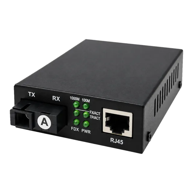
A 10/100/1000 Gigabit Fiber Media Converter — Single-Mode running a 1310 nm transmitter delivers typical transmission distances of 20 km over standard single-mode fiber (SMF). In metropolitan networks, long-reach 1550 nm DFB optics operating over ITU-T G.652.D single-mode fiber reduce attenuation to approximately 0.20 dB/km, extending continuous links up to 80 km or 120 km. Selecting a fiber media converter single mode model ensures that campus backbones remain immune to modal bandwidth bottlenecks while maintaining forward compatibility with future optical transceiver upgrades.
04Fiber to ethernet converter: fixed transceivers versus modular SFP slots
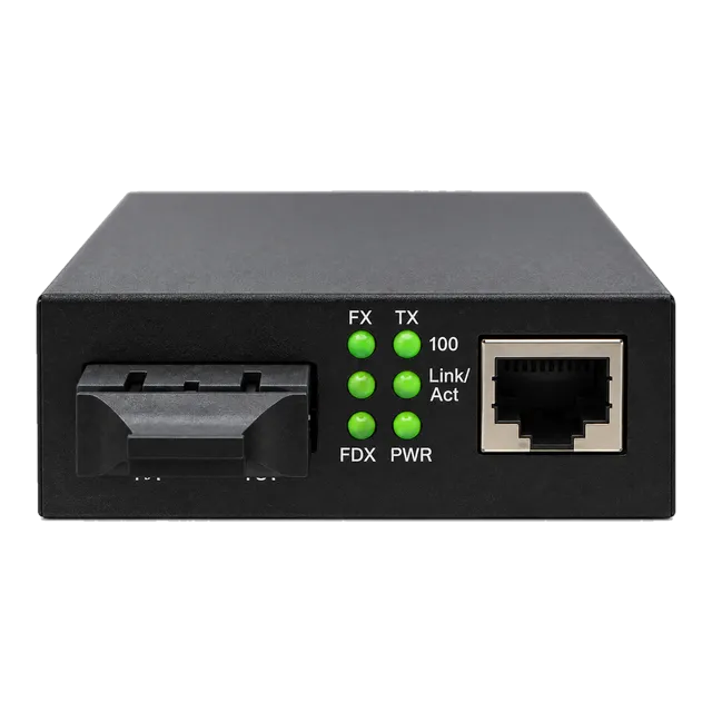
When specifying a fiber to ethernet converter, network engineers must choose between fixed onboard transceivers and modular Small Form-Factor Pluggable (SFP) transceiver cages. Fixed-transceiver converters incorporate integrated optical transmitter and receiver sub-assemblies (TOSA/ROSA), typically terminated with dual-fiber SC or ST optical connectors. These units offer lower initial acquisition costs and robust mechanical housing, making them ideal for high-volume, static installations where transmission distances and wavelengths are permanently fixed.
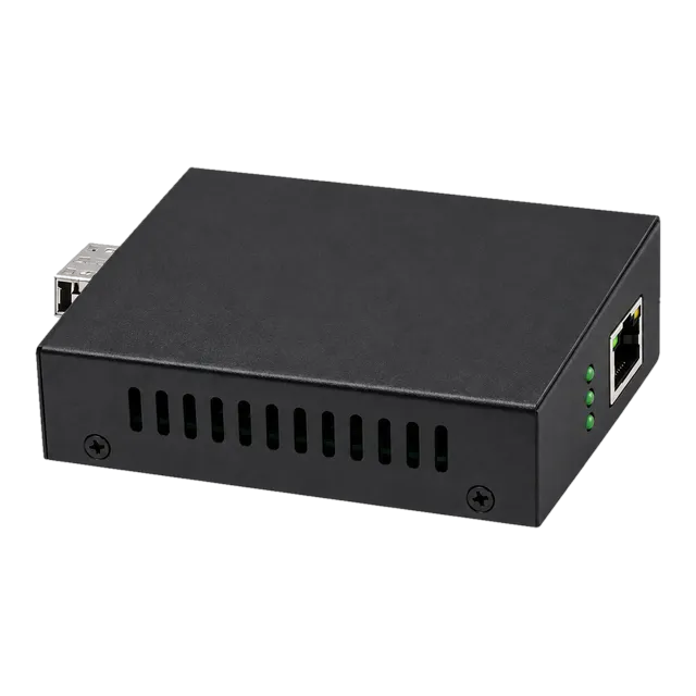
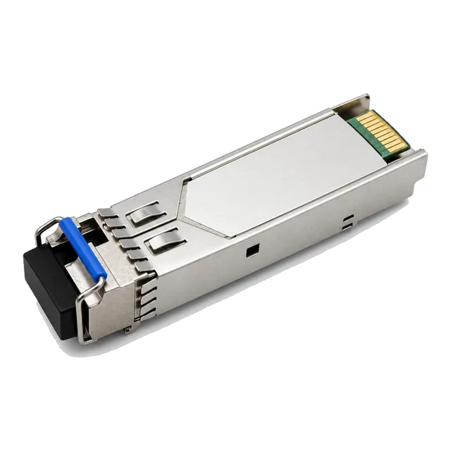
Conversely, an SFP-based ethernet fiber optic media converter offers modular adaptability by replacing the fixed optical port with an open MSA-compliant (Multi-Source Agreement) socket. An engineer can populate the cage with a 1000BASE-SX multimode transceiver, a 1000BASE LX SFP transceiver for 10 km single-mode links, or an extended-reach CWDM module. Modular SFP cages simplify maintenance; if an optical laser degrades or link requirements extend from 10 km to 40 km, the engineer replaces only the pluggable optic without unmounting the media converter or disrupting primary copper cabling.
05Fiber optic to Cat6 converter deployments and copper interfaces
A fiber optic to cat6 converter terminates high-speed optical lines and outputs onto Category 6 balanced twisted-pair copper cable, adhering to ANSI/TIA-568.2-D and ISO/IEC 11801 standards. While standard Cat5e supports 1000BASE-T up to 100 m, deploying Category 6 or Category 6A cabling alongside an ethernet converter provides significantly reduced alien crosstalk, tighter twist rates, and up to 250 MHz or 500 MHz of channel bandwidth. This structural margin ensures zero packet dropouts in dense equipment racks subject to adjacent electromagnetic interference.
The copper RJ45 port on a modern gigabit ethernet media converter features automatic MDI/MDI-X (Medium Dependent Interface Crossover) detection, eliminating the requirement for specialised crossover patch cables. The port automatically configures its transmitter and receiver pairs to match the connected network switch, router, or edge host. When deploying a fiber to cat6 converter, engineers must strictly observe the 100-metre maximum channel length rule for the copper segment, which comprises up to 90 m of solid horizontal cabling and a cumulative 10 m of stranded patch cords.
06Single-strand BiDi links: reducing infrastructure overhead
Bi-directional (BiDi) optical conversion transmits and receives data over a single strand of optical glass, effectively doubling the usable capacity of existing physical fiber plants. Standard dual-fiber links dedicate one strand to transmission (Tx) and the second strand to reception (Rx). A single mode media converter using BiDi technology incorporates an internal Wavelength Division Multiplexing (WDM) diplexer filter that isolates two distinct wavelengths traveling in opposite directions through a single fiber core.
BiDi links require complementary, matched pairs of optical transceivers. As outlined in our BiDi pairing checklist, an upstream converter transmitting at 1310 nm must receive at 1550 nm, while the downstream converter transmits at 1550 nm and receives at 1310 nm. Deploying a single mode fiber to ethernet media converter with BiDi capability saves significant operational expenditure by halving the strand leasing costs charged by telecommunications carriers and allowing service providers to provision new gigabit drops without pulling additional underground fiber cables.
07Link Fault Pass-Through (LFPT) and carrier management
Link Fault Pass-Through (LFPT) prevents silent link failures by coordinating link status between the copper RJ45 port and the optical fiber port. In basic unmanaged converters lacking LFPT, if the remote optical cable is cut, the local fiber converter detects optical carrier loss on its optical receiver but maintains an active electrical link on its copper RJ45 port. Consequently, the attached Ethernet switch continues forwarding traffic into a dead optical channel, preventing spanning tree protocols (STP/RSTP) or dynamic routing algorithms from activating redundant paths.
When LFPT is enabled via hardware DIP switches or management software, the media converter immediately shuts down the copper transmitter if its optical receiver loses light. The host switch detects an immediate link-down event on its RJ45 port and fails over traffic within milliseconds. Correspondingly, Far End Fault (FEF) signaling, defined in IEEE 802.3u Clause 24 and IEEE 802.3z Clause 37, allows a converter to transmit a designated out-of-band fault pattern over the surviving fiber strand when one strand of a duplex pair breaks, informing the remote node to isolate the connection.
08PoE-enabled fiber to RJ45 media converter options at the edge
A PoE-enabled fiber to rj45 media converter delivers both network connectivity and electrical power over a single Cat6 copper patch lead to edge field devices. In perimeter security, transportation monitoring, and large-scale manufacturing sites, edge hardware such as pan-tilt-zoom (PTZ) IP surveillance cameras, VoIP intercoms, and wireless access points (WAPs) are frequently installed on light poles or exterior walls where dedicated AC mains power is unavailable.
Integrating Power over Ethernet functionality simplifies these field deployments. Devices like the 1.25G SFP UTP PoE Media Converter combine an SFP optical transceiver cage with an IEEE 802.3af/at Power Sourcing Equipment (PSE) port capable of supplying up to 30W of 48V–57V DC power. To evaluate maximum line losses and terminal device operating budgets before specifying field hardware, engineers should reference our PoE switch power budget guide.
09Optical power budget calculation for an extended single-mode link
Calculating the optical link budget ensures that total channel attenuation does not exceed the optical dynamic range between the transmitter and receiver. The available link budget (PB) is the difference between minimum transmitter launch power (PTx_min) and maximum receiver sensitivity (PRx_sens):
PB = PTx_min - PRx_sens
Consider a gigabit ethernet to fiber converter deployment spanning 25 km of single-mode fiber operating at 1310 nm:
- Transmitter Launch Power (PTx_min): -9.0 dBm
- Receiver Sensitivity (PRx_sens): -21.0 dBm
- Available Optical Budget (PB): -9.0 dBm - (-21.0 dBm) = 12.0 dB
The total cable plant loss (Ploss) includes fiber cable attenuation (0.35 dB/km at 1310 nm), connector interface losses, and fusion splice losses:
- Fiber attenuation: 25 km × 0.35 dB/km = 8.75 dB
- Connector losses (4 mated pairs × 0.4 dB each): 1.6 dB
- Fusion splices (6 splices × 0.08 dB each): 0.48 dB
- Total channel insertion loss: 8.75 + 1.6 + 0.48 = 10.83 dB
The remaining safety margin is calculated as: Margin = PB - Ploss = 12.0 dB - 10.83 dB = 1.17 dB. Because industry standards recommend an engineering safety margin of at least 3.0 dB to account for optical component aging, temperature drift, and future field maintenance splices, this specific link requires either a higher-power optical transceiver (such as a 40 km variant with a 17 dB budget) or migration to the 1550 nm window where glass attenuation drops to 0.22 dB/km.
10Technical comparison: media converter configurations and specifications
Selecting an optical to copper converter requires matching physical port types, wavelengths, operational temperature ranges, and transmission protocols across target environments. The following comparison highlights structural parameters across standard converter classes:
| Converter Classification | Optical Port & Polish | Copper Port & Standard | Typical Wavelength (nm) | Maximum Distance | Operating Temp (°C) |
|---|---|---|---|---|---|
| Fixed SMF Gigabit | Duplex SC / UPC | RJ45 / 1000BASE-T | 1310 | 20 km | 0 to +50 |
| Modular SFP Gigabit | SFP Cage (LC / UPC) | RJ45 / 1000BASE-T | 850 / 1310 / 1550 | 0.55 km to 120 km | -10 to +60 |
| BiDi WDM Simplex | Simplex SC or LC | RJ45 / 1000BASE-T | 1310 Tx / 1550 Rx | 20 km to 40 km | 0 to +50 |
| Multigigabit SFP | SFP+ Cage (LC) | RJ45 / 2.5GBASE-T | 850 / 1310 | 0.3 km to 40 km | -10 to +60 |
| PoE+ Industrial SMF | Duplex SC or SFP | RJ45 / 802.3at (30W) | 1310 | 20 km | -40 to +75 |
For industrial cabinets subject to extreme ambient thermal fluctuations, engineers should specify wide-temperature models rated from -40°C to +75°C with dual redundant DC terminal blocks rather than standard commercial AC desktop adapters.
11Troubleshooting link loss, duplex mismatches, and DDM diagnostics
Troubleshooting intermittent drops on a media converter for fiber optic cable requires isolating whether the failure originates in the optical domain, the copper channel, or PHY auto-negotiation. Common issues emerge from improper configuration of speed and duplex settings. If a managed switch port is forced to 1000 Mbps Full Duplex while the connected converter operates in auto-negotiation mode, a duplex mismatch occurs, generating excessive frame check sequence (FCS) errors and severe packet loss under heavy load.
- Verify physical fiber polarity: ensure that the local transmitter (Tx) connects to the remote receiver (Rx). Reversing duplex LC or SC connectors is the most common cause of optical link failure.
- Inspect optical power levels: using an optical power meter or Digital Diagnostic Monitoring (DDM) on SFP models, verify that received light falls between the receiver sensitivity and optical saturation (overload) thresholds.
- Examine copper cable lengths: ensure Cat6 patch runs do not exceed 100 m total channel length, and confirm termination conforms to ANSI/TIA-568-B pinouts using an automated cable certifier.
- Validate DIP switch settings: confirm that Link Fault Pass-Through (LFPT) is configured identically at both ends of the fiber circuit to prevent false-positive carrier drops during initial commissioning.
12Engineering checklist for your next fiber converter procurement
Before submitting a formal Request for Quotation (RFQ) for an ethernet fiber optic converter or a larger network expansion, review this engineering checklist to ensure hardware compatibility and long-term operational stability:
- Interface Modularity: Determine whether fixed optical connectors (SC/ST) or hot-swappable SFP transceiver cages better serve long-term network flexibility and spare parts logistics.
- Fiber Cable Type: Confirm existing physical cabling is 9/125 µm single-mode (OS2) or 50/125 µm multimode (OM4) to prevent severe modal mismatch attenuation (often exceeding 10 dB).
- Optical Power Budget: Calculate total fiber channel loss, including cable attenuation, connector mated pairs, and fusion splices, retaining an engineering safety margin of at least 3.0 dB.
- Fault Management: Verify that hardware supports Link Fault Pass-Through (LFPT) and Far End Fault (FEF) signaling to ensure immediate switch failover upon fiber severance.
- Environmental Specs: Specify commercial grade (0°C to 50°C) or hardened industrial grade (-40°C to 75°C) with DIN-rail mounting and 12V–48V DC redundant power terminal inputs.
- Power Requirements: Establish whether edge copper drops require IEEE 802.3at PoE+ power injection to drive remote surveillance cameras, access points, or industrial sensors.
For large enterprise rollouts, browsing the complete media converter product catalogue allows procurement teams to match chassis-mount multi-slot card systems with standalone edge converters, maintaining operational consistency across the network topology.
13Frequently asked questions
What is the difference between single-mode and multimode fiber to ethernet converters?
Single-mode converters use narrow 9/125 µm core fiber with 1310 nm or 1550 nm lasers to achieve transmission distances up to 120 km. Multimode converters use 50/125 µm or 62.5/125 µm core fiber with 850 nm LEDs or VCSELs, limiting link lengths to a maximum of 550 m due to modal dispersion.
Does a fiber to ethernet converter add latency to the network?
Latency depends on converter architecture. Layer 1 physical converters introduce negligible sub-microsecond latency as they convert raw bits directly. Layer 2 store-and-forward switching converters buffer incoming packets to verify frame integrity and adapt speeds, introducing a modest delay typically ranging between 2 and 5 microseconds per frame.
Can I connect a 1000BASE-T copper switch to a 100BASE-FX optical converter?
Only if the media converter supports multi-rate Layer 2 switching. A Layer 1 converter requires identical speeds on both interfaces. A multi-rate 10/100/1000Base-T to 100Base-FX switching converter can negotiate 1000 Mbps with the switch over Cat6 while translating frames to 100 Mbps optical output over the fiber link.
What is Link Fault Pass-Through (LFPT) on a media converter?
Link Fault Pass-Through (LFPT) is a diagnostic feature that links the carrier status of copper and optical ports. If the fiber link breaks, the converter automatically disables its copper port. This signals the connected network switch to drop the port immediately, triggering fast spanning tree or routing failover.
Do I need to install fiber to ethernet converters in pairs?
Not always. While standalone converters are frequently deployed in pairs to bridge two copper devices across a dedicated fiber cable, an ethernet converter can also connect directly to a switch equipped with an optical SFP port, provided speed, wavelength, and optical mode match exactly.
Technical review note: confirm model-specific specifications with the product datasheet and the intended host documentation. Product images and application photographs are illustrative.
Discuss this with our team