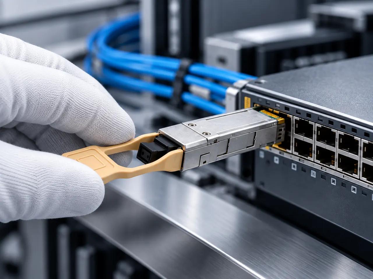
Selecting an ethernet media converter requires matching physical-layer forwarding modes to latency tolerances, calculating real optical attenuation budgets, verifying Link Fault Pass-Through support, and auditing power supply reliability against industrial environmental baselines.
01What is an ethernet media converter and how does it function?
An ethernet media converter is a dedicated physical-layer hardware device that interconnects disparate transmission media—most commonly copper twisted-pair cabling and optical fibre. In accordance with IEEE 802.3 standards, local area network copper interfaces such as 1000BASE-T are physically bound by an insertion loss limit that caps operational channel lengths at 100 metres over Category 5e, Category 6, or Category 6A cabling. Media converters eliminate this distance barrier by translating the electrical differential signals transmitted over copper into modulated photonic pulses carried across optical fibre cables.
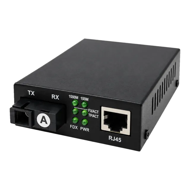
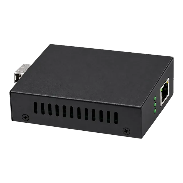
Internally, a standard converter comprises an RJ45 physical layer transceiver (PHY), a media access control (MAC) packet processor or repeat-state logic, and an optical transceiver port. The optical port is implemented either as a fixed optical sub-assembly (such as dual SC or simplex BiDi ST/SC connectors) or as a modular Small Form Factor Pluggable (SFP) socket governed by SFF Committee specifications. Modern network architectures deploy standalone units, high-density modular chassis platforms, or DIN-rail industrial devices to extend campus backbones, link remote surveillance cameras, and integrate isolated operational technology (OT) networks without requiring complete core switch upgrades. For engineers planning modular uplinks, using standard 1.25G SFP transceivers inside open-slot converters provides future-proof flexibility across variable site distances.
02Layer 1 physical translation versus Layer 2 switching architecture
Media converters operate using either pure Layer 1 physical translation or Layer 2 store-and-forward switching architectures. The internal architecture determines forwarding latency, buffer handling, frame size support, and duplex negotiation behaviour across the network boundary.
Pure Layer 1 converters function as transparent bit-level repeaters. They do not parse frame preambles, inspect MAC addresses, or buffer packets in memory. Consequently, a Layer 1 converter delivers absolute minimum propagation latency—typically between 50 and 100 nanoseconds—making it the preferred architecture for time-sensitive financial execution fabrics and synchronous industrial control loops. However, pure Layer 1 devices require identical data rates and duplex modes on both sides; a 1000BASE-T copper interface cannot link to a 100BASE-FX optical link via a physical-layer repeater.
Conversely, Layer 2 media converters incorporate an integrated dual-port bridge switch with an internal SRAM packet buffer. They receive complete Ethernet frames, run a cyclic redundancy check (CRC) to discard corrupted frames, and forward valid packets between mismatched rates (for instance, autonegotiating 10/100/1000BASE-T on copper while driving a fixed 1.25 Gb/s optical interface). This store-and-forward mechanism introduces variable packet latency, typically ranging from 3 to 15 microseconds depending on frame length. Devices like the 10/100/1000 Gigabit Fiber Media Converter — Single-Mode leverage Layer 2 architectures to adapt legacy 100 Mbps edge endpoints into modern Gigabit aggregation topologies with minimal engineering intervention.
03Fixed optical transceivers versus modular SFP media converters
Choosing between fixed-optics converters and modular SFP media converters impacts network maintainability, optical troubleshooting workflows, and total lifecycle capital expenditure. Fixed-interface units incorporate a factory-soldered transmitter optical sub-assembly (TOSA) and receiver optical sub-assembly (ROSA) with external connector barrels, whereas modular converters supply an unpopulated MSA-compliant cage.
| Engineering Metric | Fixed-Optics Converter | Modular SFP Converter |
|---|---|---|
| Optical Interface | Dual SC, ST, or Simplex SC | Pluggable LC / SC via SFP (SFF-8472) |
| Diagnostic Visibility | Basic LED Carrier Detect only | Full Digital Diagnostics Monitoring (DDM) |
| Inventory Spares Ratio | 1 spare unit per optical variant | 1 common chassis + discrete SFP modules |
| Wavelength Upgradability | Requires complete hardware replacement | Hot-swappable module swap in under 1 minute |
| Failure Isolation | Unit discard on optical burn-out | Independent module or chassis replacement |
| Upfront Hardware Cost | Lower initial cost (fixed bill of materials) | Slightly higher initial investment |
While fixed-optics units serve predictable, static point-to-point routes, modular SFP platforms provide vital link-level instrumentation. The SFF-8472 specification exposes internal temperature, transmitter bias current, transmit optical power, and received optical power (Rx power) over a 2-wire serial I2C bus. Modular systems allow technicians to verify degradation prior to complete link loss, an essential capability detailed in our guide to what DDM can tell you about an optical link.
04Calculating the optical power budget for an ethernet media converter
A media converter link must maintain an optical power budget sufficient to overcome cumulative attenuation across the physical cable plant without overloading the receiving photodiode. Calculating this margin ensures reliable operation over the target distance.
The optical power budget ($P_{\text{budget}}$) represents the difference between the minimum optical transmitter output power ($P_{\text{Tx\_min}}$) and the maximum receiver sensitivity ($P_{\text{Rx\_sens}}$):
$$P_{\text{budget}} = P_{\text{Tx\_min}} - P_{\text{Rx\_sens}}$$
Total link attenuation ($A_{\text{total}}$) is calculated by summing fibre cable attenuation, connector insertion losses, splice losses, and an engineering safety margin:
$$A_{\text{total}} = (L \times \alpha) + (N_{\text{conn}} \times L_{\text{conn}}) + (N_{\text{splice}} \times L_{\text{splice}}) + M_{\text{safety}}$$
Consider an actual campus deployment spanning 18.5 km using standard single-mode ITU-T G.652.D fibre at 1310 nm, connecting a modular media converter running a standard 20 km optical module:
- Transmitter minimum output power ($P_{\text{Tx\_min}}$): -9.0 dBm
- Receiver sensitivity ($P_{\text{Rx\_sens}}$): -20.0 dBm
- Receiver saturation damage threshold: -3.0 dBm
- Available Power Budget: $-9.0\text{ dBm} - (-20.0\text{ dBm}) = 11.0\text{ dB}$
- Fibre cable attenuation ($\alpha$ at 1310 nm): 0.35 dB/km $\times$ 18.5 km = 6.475 dB
- Connector losses ($N_{\text{conn}}$): 4 patch connections $\times$ 0.4 dB/connector = 1.6 dB
- Fusion splice losses ($N_{\text{splice}}$): 2 splices $\times$ 0.1 dB/splice = 0.2 dB
- Engineering safety margin ($M_{\text{safety}}$): 2.5 dB (covering temperature flux and component ageing)
- Total Link Attenuation: $6.475 + 1.6 + 0.2 + 2.5 = 10.775\text{ dB}$
The available budget of 11.0 dB exceeds the total calculated attenuation of 10.775 dB by a residual margin of 0.225 dB, confirming the 18.5 km span will operate stably. For links exceeding 20 km, engineers should reference our methodology for calculating optical link budgets to avoid signal degradation.
05Single-mode versus multimode fibre selection criteria
Fibre selection dictates both transceiver component costs and maximum reachable transmission distances. Network planners must align converter transceivers with the installed optical infrastructure.
Multimode optical fibre (OM1 through OM5) possesses a wider core diameter (typically 50 μm or 62.5 μm), allowing multiple spatial light modes to propagate simultaneously. While multimode media converters utilise economical vertical-cavity surface-emitting lasers (VCSELs) operating at 850 nm, modal dispersion limits 1 Gb/s transmission distances to 550 metres over OM2, OM3, or OM4 infrastructure. Multimode links remain confined to intra-building risers, legacy data halls, and local server rooms.
Single-mode optical fibre (ITU-T G.652.D or bend-insensitive G.657.A1) features a narrow core diameter of 8.2 to 9.2 μm, restricting light propagation to a single transverse mode and virtually eliminating modal dispersion. Single-mode media converters utilise Fabry-Pérot (FP) or Distributed Feedback (DFB) laser diodes emitting at 1310 nm or 1550 nm. This profile permits transmission reaches ranging from 10 km up to 120 km. Single-mode fibre is standard practice for inter-building campus loops, metropolitan ring distribution, and perimeter surveillance feeds.
06Single-strand BiDi optical transmission architecture
Bidirectional (BiDi) media converters transmit and receive downstream and upstream data over a single optical fibre strand using wavelength-division multiplexing (WDM). By partitioning optical paths by wavelength, BiDi hardware cuts external fibre core consumption by 50% across saturated conduit paths.
BiDi transceivers incorporate an integrated diplexer filter that routes incoming and outgoing light along distinct optical bands. In Gigabit topologies, standards dictate matched transceiver pairs operating at 1310 nm and 1550 nm, or 1310 nm and 1490 nm:
- Side A Device: Transmits on 1310 nm ($\lambda_1$) using an internal laser diode; receives on 1550 nm ($\lambda_2$) through the diplexer.
- Side B Device: Transmits on 1550 nm ($\lambda_2$) using an internal laser diode; receives on 1310 nm ($\lambda_1$) through the diplexer.
BiDi links require strict point-to-point pairing discipline. Deploying identical transceivers on both sides results in receiver blindness, as both devices transmit on the same wavelength while listening on the unilluminated frequency. Network engineers can consult our BiDi module pairing checklist to verify site allocations before dispatching field technicians.
07Deploying an ethernet media converter with Power over Ethernet
A Power over Ethernet (PoE) media converter injects DC operating power directly into Category-rated balanced copper cabling while concurrently converting the upstream optical signal. This dual-purpose architecture eliminates the expense of running localized AC mains lines to remote peripheral field hardware.
Commercial PoE media converters conform to standardized IEEE operational tiers:
- IEEE 802.3af (PoE): Delivers up to 15.4 W at the source port, guaranteeing a minimum of 12.95 W to the Powered Device (PD) across 100 metres of twisted pair.
- IEEE 802.3at (PoE+): Delivers up to 30.0 W at the source port, guaranteeing 25.5 W to the PD; ideal for motorized Pan-Tilt-Zoom (PTZ) optical cameras, dual-band Wi-Fi access points, and remote access controllers.
- IEEE 802.3bt (Type 3 / Type 4 PoE++): Uses all four cable pairs to inject 60 W to 90 W, powering outdoor heated camera enclosures, digital signage, and remote thin clients.
The 1.25G SFP UTP PoE Media Converter combines a flexible optical SFP slot with an internal 48V–57V power supply capable of supplying 30 W over RJ45. This setup allows technicians to terminate remote surveillance runs over single-mode fibre backbones without needing a local electrical supply at each drop pole.
08Industrial versus commercial environmental specifications
Environmental operating conditions dictate the component engineering and form factor of a media converter. Commercial converters suit climate-controlled data closets, whereas industrial units withstand extreme temperatures, electromagnetic noise, and physical shock.
Commercial units rely on sheet-metal enclosures, commercial-grade silicon rated from 0°C to +50°C, internal switching power supplies with modest MTBF figures, and external plug-in AC-to-DC desktop transformers. These devices mount into standard rack trays or rest directly on office shelves.
Industrial media converters feature ruggedised, fanless cast-aluminium chassis rated to IP30 or IP40, distributing heat purely through convection. Internal components must hold operational stability across a hardened thermal window from -40°C to +85°C. Critical electrical additions include redundant DC power inputs (typically dual 12–48 VDC terminal blocks), heavy-duty reverse polarity protection, and optical galvanic isolation. Industrial platforms must also meet stringent electromagnetic compatibility (EMC) standards, such as IEC 61000-4-2 (Electrostatic Discharge), IEC 61000-4-4 (Electrical Fast Transient/Burst), and IEC 61000-4-5 (Surge Immunity), ensuring uninterrupted packet forwarding alongside variable frequency drives and high-voltage relays.
09Critical fault detection: Link Fault Pass-Through and Far End Fault
Link Fault Pass-Through (LFPT) and Far End Fault (FEF) prevent silent connection failures across heterogeneous media boundaries. Without these mechanisms enabled, a converter acts as an unmanaged isolation barrier that blinds connected host switches to remote cable breaks.
In standard asynchronous operation, if an optical strand cuts out between two remote buildings, the local media converter maintains its copper link integrity to the core switch. The switch treats the interface as up, continuing to route packets into an unmonitored physical void. This creates black-hole routing loops that defeat Spanning Tree Protocol (STP), Rapid Spanning Tree Protocol (RSTP), and Link Aggregation Group (LAG) failover states.
- Link Fault Pass-Through (LFPT): When the media converter detects a loss of signal (LOS) on its optical receiver, it disables the transmitter on its local copper RJ45 port. The host switch detects the immediate physical link-down event and automatically triggers an STP/RSTP reconvergence path within milliseconds.
- Far End Fault (FEF): Defined in IEEE 802.3u, FEF detects directional signal loss on dual-fibre circuits. If Side A loses its receive signal from Side B, Side A alters its transmitted carrier signal to send an explicit FEF code group back to Side B. This informs Side B that its transmit path is severed, instructing both ends to take their copper links offline.
10Multi-rate migration: 100M, 1G, 2.5G, and 10G topologies
Modern network backbones increasingly require bandwidth beyond standard 1 Gb/s links. Deploying multi-rate media converters provides scalable upgrade paths across corporate and industrial physical networks.
While standard 10/100/1000BASE-T units suffice for basic building management and legacy PLCs, enterprise access networks face bandwidth constraints driven by Wi-Fi 6/6E access points and 4K machine vision cameras. The IEEE 802.3bz standard establishes 2.5GBASE-T and 5GBASE-T, delivering multi-gigabit transport over existing Cat5e and Cat6 structured plant cabling. Media converters equipped with multi-rate copper and optical interfaces bridge this intermediate gap efficiently.
Using the 2.5G Fiber to Ethernet Media Converter, an engineer can accept 100M, 1000M, or 2.5G copper connections from an enterprise access point and push that traffic directly across a 2.5 Gb/s optical SFP link back to an aggregation switch, bypassing the need for end-to-end multi-gigabit switch overhauls. At the core, 10GBASE-T to 10GBASE-SR/LR converters link high-capacity storage servers directly into 10 Gigabit campus cores.
11Alternative physical media: IP ethernet over legacy coaxial infrastructure
Upgrading legacy analog security networks does not always necessitate stripping out installed coaxial cabling. In historic buildings, maritime vessels, and underground rail links, pulling new Cat6A or optical fibre lines is frequently cost-prohibitive.
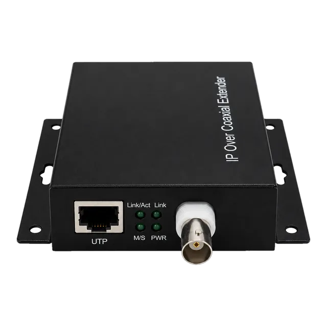
Ethernet-over-Coax (EoC) media converters overcome this physical constraint by converting standard IEEE 802.3 baseband packets into high-frequency orthogonal frequency-division multiplexing (OFDM) modulated RF carriers. Running over 75-ohm coaxial cable (such as RG59, RG6, or RG11), hardware such as the IP Ethernet to Coax Media Converter — RJ45 to BNC delivers 10/100 Mbps full-duplex Ethernet data over continuous distances reaching up to 1,500 metres. This reach significantly outperforms twisted-pair copper limits while protecting capital budgets during physical IP migration phases.
12Troubleshooting physical layer converter faults and optical loss
Systematic troubleshooting of an ethernet media converter requires isolating whether an intermittent fault originates across the copper run, the optical plant, or the transceiver conversion logic. Field engineers should follow an ordered diagnosis procedure.
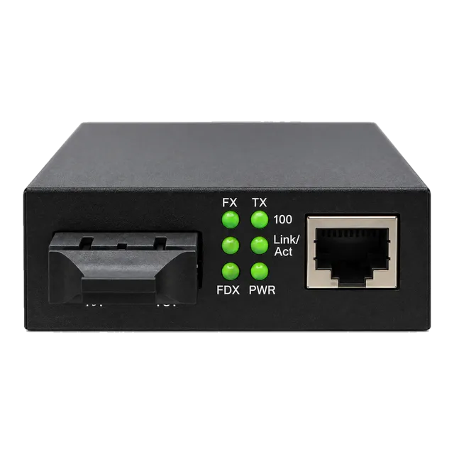
- Inspect Front-Panel Diagnostics: Observe the LED carrier indicators for PWR (power integrity), FDX/COL (duplex status), TP LNK/ACT (copper link established and frame activity), and FX LNK/ACT (optical carrier detect). If TP is solid while FX is unlit, the fault lies entirely within the optical path.
- Verify DIP Switch Configuration: Ensure hardware DIP switches for Link Fault Pass-Through (LFPT), autonegotiation, and full/half duplex settings match between paired local and remote endpoints. Mismatched LFPT settings can prevent one port from linking up.
- Measure Receiver Optical Power: Connect an optical power meter calibrated to the operational wavelength (850, 1310, or 1550 nm) directly to the receiving connector barrel. Compare this measurement against the sensitivity specification. If the reading drops below sensitivity (e.g., -23 dBm on a -20 dBm threshold), run visual fault locating (VFL) to inspect for physical bend limits or crushed jackets.
- Clean Optical Connector End-Faces: Clean all male LC or SC ferrule tips using a clean-room grade lint-free 1.25 mm or 2.5 mm optical click cleaner. Inspect end-faces using a 400x optical fibre scope; particulate contamination accounts for over 70% of field insertion losses.
- Perform Loopback Testing: For modular SFP converters, install an optical loopback plug between the transmitter and receiver ports. If the FX LED lights up immediately and the host switch reports zero frame alignment errors on that interface, the transceiver and converter electronics are operating within spec.
13Procurement cost breakdown: evaluating media converter fiber price and TCO
A realistic evaluation of total cost of ownership (TCO) extends beyond the base media converter fiber price to incorporate optic modules, thermal chassis, and maintenance reserves. Strategic bulk procurement hinges on identifying cost trade-offs between unmanaged edge converters and chassis-managed core hardware.
Standalone unmanaged fixed-optics converters represent the lowest upfront unit cost. However, they carry higher operational maintenance costs due to zero remote diagnostic capability. Open-slot modular SFP converters carry a minor initial hardware premium (15% to 25%), but yield lower aggregate costs across multi-site rollouts because standard transceivers can be bulk-sourced and hot-swapped as network bandwidth requirements evolve.
For enterprise distribution centres and telco headends, high-density 19-inch 14-slot or 16-slot rackmount chassis yield significant savings over discrete desktop units. Centralised chassis systems supply redundant AC/DC hot-swap power bays, eliminating dozens of external power adapters while centralising Simple Network Management Protocol (SNMP) monitoring over an out-of-band management module.
14Engineering checklist for specifying an ethernet media converter RFQ
Engineers and procurement teams should use this technical checklist to compile an unambiguous Request for Quotation (RFQ) for media converters and related transceivers.
- Throughput Data Rate: Fixed 100BASE-FX, 1000BASE-T/1000BASE-X, multi-rate 2.5 Gb/s, or 10GBASE-T to 10GBASE-R.
- Optical Form Factor: Fixed dual SC/ST, simplex BiDi SC, or open SFF MSA-compliant SFP/SFP+ cage.
- Fibre Channel Plant: Single-mode (9/125 μm ITU-T G.652.D / G.657.A1) or Multimode (50/125 μm OM3 or OM4).
- Optical Budget Metrics: Transmission distance (e.g., 550 m, 20 km, 40 km, 80 km), operational wavelength (850 nm, 1310 nm, 1550 nm, or CWDM), and receiver saturation safety floor.
- Advanced Layer 1/2 Control: Hardware DIP switch support for Link Fault Pass-Through (LFPT), Far End Fault (FEF), and frame size support (standard 1518 bytes versus 9K/10K Jumbo frames).
- Power & Environment: Commercial (0°C to 50°C) with AC adapter, or Industrial (-40°C to +85°C) with dual 12–48 VDC terminal inputs, DIN-rail mounting bracket, and IP30 metal casing.
- Power Delivery Options: Non-PoE, IEEE 802.3af (15.4 W), IEEE 802.3at (30 W), or IEEE 802.3bt (60 W / 90 W).
For modular deployments, engineering teams can consult our guide on which documents should accompany your optics RFQ to verify testing, burn-in validation, and compliance parameters before finalizing volume purchase contracts.
15Frequently asked questions
What is the maximum distance supported by an ethernet media converter?
An ethernet media converter supports links ranging from 550 metres over multimode fibre up to 120 kilometres over single-mode fibre using 1550 nm DFB laser transmitters. Actual supported reach depends entirely on the link's optical power budget, cable attenuation per kilometre, and connector insertion loss.
Does an ethernet media converter increase network latency?
Pure Layer 1 physical-layer media converters add negligible propagation delay, typically between 50 and 100 nanoseconds. Layer 2 store-and-forward media converters introduce slightly more latency, averaging between 3 and 15 microseconds, because the integrated switch chip buffers and inspects complete Ethernet frames before forwarding.
Can a media converter connect single-mode fibre to multimode fibre?
Yes, dual-slot modular media converters can bridge single-mode to multimode fibre directly. By populating one SFP cage with an 850 nm multimode module and the other with a 1310 nm single-mode module, the converter handles optical-electrical-optical (O-E-O) wavelength regeneration across both physical cable plants.
Why is Link Fault Pass-Through (LFPT) critical on media converters?
Link Fault Pass-Through ensures that a physical cable break on the optical side causes the converter to shut down its corresponding copper link. This notifies connected host switches of the failure immediately, triggering rapid Spanning Tree (RSTP) failover instead of silently black-holing network traffic.
Can I use any SFP transceiver in a modular media converter?
Most modular media converters accept any MSA-compliant SFP module operating at the matching data rate. Unlike vendor-locked switches, unmanaged open-architecture converters do not require custom EEPROM vendor coding, though industrial-rated installations require industrial temperature-grade SFP optics to avoid thermal failure.
Technical review note: confirm model-specific specifications with the product datasheet and the intended host documentation. Product images and application photographs are illustrative.
Discuss this with our team