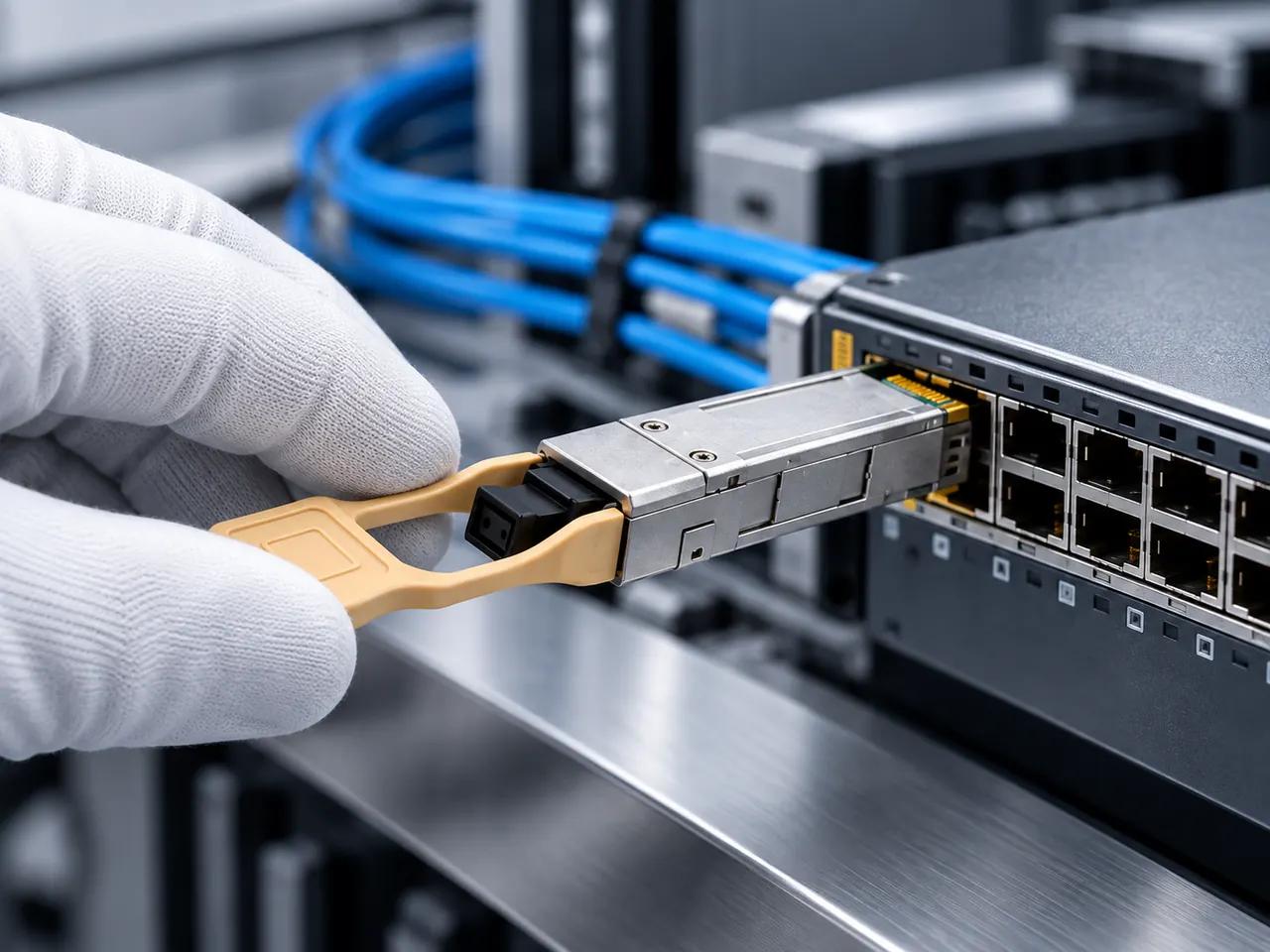
A managed switch ensures deterministic throughput and network isolation via hardware-based Layer 2/3 forwarding, 802.1Q segmentation, and SFF-8472 optical diagnostics, balancing management depth with strict wire-speed backplane sizing.
01Managed switch architecture and core operation
A managed switch provides granular administrative control, protocol monitoring, and deterministic packet handling across local network segments. Unlike transparent bridging devices, a managed switch separates the control plane from the data plane, allowing network engineers to configure port parameters, shape traffic, isolate traffic flows via IEEE 802.1Q Virtual Local Area Networks (VLANs), and monitor link health remotely. In modern facilities, deploying a managed switch guarantees that mission-critical supervisory control, voice, and storage frames receive dedicated queuing priority over bulk data transfers.
At its physical foundation, a managed switch integrates an Application-Specific Integrated Circuit (ASIC) packet processor paired with an onboard microprocessor running an embedded operating system. The ASIC executes wire-speed frame parsing, Media Access Control (MAC) address table lookups, and Access Control List (ACL) filtering directly in hardware. Meanwhile, the central processor handles network management protocols including Simple Network Management Protocol (SNMPv2c/v3), Secure Shell (SSH), Link Layer Discovery Protocol (LLDP, IEEE 802.1AB), and spanning tree convergence algorithms. For enterprise backbones and industrial substations, this architectural partitioning prevents control plane traffic storms from starving user-plane transit packets.
02Managed switch vs unmanaged switch: architectural comparison
The core distinction between a managed switch and an unmanaged switch lies in administrative visibility, loop mitigation mechanisms, and traffic isolation capabilities. An unmanaged switch operates purely as a plug-and-play device using a fixed MAC learning state machine, forwarding broadcast, unknown unicast, and multicast (BUM) traffic to all active ports on the same broadcast domain without filtration. In contrast, a managed ethernet switch allows operators to subdivide physical hardware into isolated broadcast domains, apply rate limiting, and track physical layer errors using remote telemetry.
In topologies prone to physical cable manipulation or redundant cabling loops, unmanaged switches lack loop detection mechanisms like Spanning Tree Protocol (STP), leading to catastrophic network-wide broadcast storms within milliseconds. While unmanaged units suffice for basic desktop drops or isolated edge endpoints, critical infrastructure requires the administrative control of a managed unit. A side-by-side technical comparison illustrates the baseline trade-offs across deployment tiers:
| Capability | Unmanaged Switch | Smart Managed Switch | Fully Managed Switch |
|---|---|---|---|
| Management Interfaces | None (Fixed ASIC) | HTTP/HTTPS Web GUI | CLI (Console/SSH), SNMPv3, REST API |
| VLAN Support (IEEE 802.1Q) | None (Single Domain) | Basic Port/Tag-based (up to 64–128 VIDs) | Full 4,094 VIDs, Private VLANs, QinQ |
| Loop Prevention | None or rudimentary loop detect | RSTP (IEEE 802.1w) | RSTP, MSTP (802.1s), ITU-T G.8032 ERPS |
| Transceiver Diagnostics | None | Basic link status | Full SFF-8472 DDM/DOM optical telemetry |
| Forwarding Control | Standard Store-and-Forward | Store-and-Forward, basic QoS | L2/L3 Line-rate forwarding, Dynamic ACLs |
Engineers evaluating basic infrastructure can review our unmanaged ethernet switch guide to identify specific environments where unmanaged hardware remains commercially viable.
03Smart managed switch vs fully managed ethernet switch
A smart managed switch provides an intermediate operational tier between plug-and-play devices and enterprise-grade switches, offering essential Layer 2 configuration through a web browser interface without the overhead of a full Command Line Interface (CLI). Often designated as a "smart-lite" or "web-managed" unit, a smart managed switch incorporates essential features such as port mirroring, Quality of Service (QoS) prioritization, and 802.1Q tagging, but deliberately omits complex routing protocols, deep command automation, and multi-instance spanning tree engines.
For network engineers managing distributed branch offices or discrete automation cells, choosing between a smart managed switch and a fully managed ethernet switch hinges on configuration scale and orchestration requirements. Fully managed platforms incorporate comprehensive console CLI access via RS-232/USB, robust SNMP MIB support for enterprise Network Management Systems (NMS), TACACS+/RADIUS authentication, and Layer 3 static or dynamic routing (OSPF, BGP). When managing deployments across hundreds of sites, a smart switch requires manual web-form updates, whereas a fully managed switch supports automated configuration deployment via Ansible, Netconf, or Python scripts over SSH.
04Selecting a small managed switch for edge and cabinet deployments
A small managed switch delivers compact port counts—typically 4 to 10 ports—specifically designed for edge installations, roadside cabinets, and industrial DIN-rail enclosures. Deploying enterprise 19-inch 48-port switches into tight field enclosures is physically impossible due to depth and cooling constraints. A small managed switch packs Layer 2 management features, redundant direct current (DC) power inputs, and extended temperature tolerances into an enclosure occupying minimal cabinet footprint.
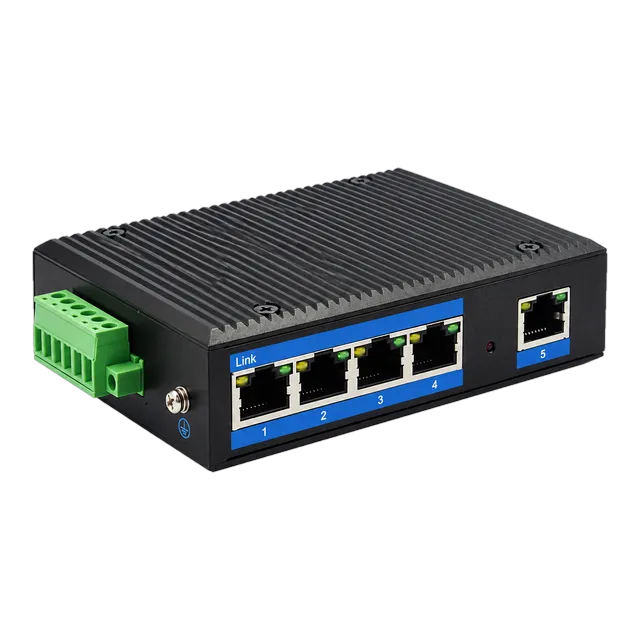
For field engineers building remote surveillance or industrial telemetry links, devices like the Outdoor Industrial Gigabit Ethernet Switch — 5× RJ45 Port provide ruggedized operation across -40°C to +85°C environments without relying on failure-prone internal fans. When selecting an edge managed switch, always verify whether the unit uses convection cooling, requires external DIN-rail power supplies (typically 12–48V DC), and includes surge immunity compliant with IEC 61000-4-5 standards to survive utility-grade transient surges.
05Low cost managed switch engineering: evaluating cheap managed switch trade-offs
A low cost managed switch achieves an accessible price point by utilizing highly integrated system-on-chip (SoC) architectures and plastic or lightweight metal housings, but introduces performance limits that require scrutiny. When procurement teams seek a cheap managed switch or inexpensive managed switch to meet capital expenditure limits, they must evaluate the hardware specifications that switch manufacturers trim to hit aggressive price targets.
The primary compromise in an inexpensive managed switch involves packet buffer memory and control plane processing power. While high-tier industrial switches incorporate deep shared packet buffers (2 MB to 12 MB) to prevent packet loss during micro-bursts, a low cost managed switch frequently allocates 512 KB or less across all ports. In environments handling intermittent high-bandwidth video streams or industrial sensor polling, these shallow buffers overflow, resulting in dropped frames. Furthermore, cheap managed switches often restrict their MAC address table capacity to 2,000–4,000 entries and rely on low-power CPUs that introduce significant latency when processing SNMP queries or parsing management web pages under heavy network traffic loads.
06Switching fabric capacity and packet forwarding calculations
A managed switch provides true non-blocking line-rate performance only when its internal backplane bandwidth equals or exceeds the aggregate theoretical throughput of all physical ports operating simultaneously in full-duplex mode. Network designers must calculate both switching capacity (in gigabits per second, Gbps) and forwarding rate (in million packets per second, Mpps) to ensure the internal ASIC fabric does not introduce packet delay or frame loss under maximum load.
To evaluate a switch architecture, consider an 8-port Gigabit switch equipped with 2 additional 1.25 Gbps SFP uplink ports. The calculation proceeds as follows:
- Calculate Non-Blocking Switching Fabric: Every port transmits and receives concurrently in full-duplex. Multiply the number of ports by their physical port speed and double the result:
Fabric Bandwidth = (8 × 1 Gbps × 2) + (2 × 1.25 Gbps × 2) = 16 Gbps + 5 Gbps = 21 Gbps. The switch backplane must provide at least 21 Gbps to guarantee non-blocking throughput. - Calculate Wire-Speed Packet Forwarding Rate: Standard Ethernet frames require an 8-byte preamble/start-frame-delimiter and a 12-byte inter-frame gap (IFG). The smallest valid Ethernet frame is 64 bytes. Thus, a minimum-sized frame occupies 84 bytes (672 bits) on the physical wire.
At 1 Gbps (1,000,000,000 bps), the maximum packet rate per port is:1,000,000,000 bps / 672 bits = 1,488,095 pps ≈ 1.488 Mpps.
For our 10-port switch (8 GbE ports + 2 SFP uplinks running at 1.25 Gbps line rate with 1.488 Mpps effective throughput per 1000BASE link):Total Forwarding Rate = 10 × 1.488 Mpps = 14.88 Mpps.
If the vendor datasheet specifies a forwarding rate lower than 14.88 Mpps or a switching fabric below 21 Gbps, the switch uses an oversubscribed architecture that drops minimum-sized frames under saturated conditions. Complete design criteria for backbone and access switching fabrics can be reviewed in our ethernet switch selection and RFQ guide.
07Traffic segmentation and priority mapping in a managed lan switch
A managed lan switch establishes deterministic boundaries across enterprise networks through IEEE 802.1Q tag-based VLANs and IEEE 802.1p Quality of Service (QoS) queuing. By inserting a 4-byte VLAN tag into standard Ethernet frame headers—containing a 12-bit VLAN Identifier (VID) and a 3-bit Priority Code Point (PCP)—the managed switch categorises traffic into distinct broadcast domains across shared physical infrastructure.
Hardware-level queuing on a managed LAN switch prevents bulk backup routines or public Internet requests from interrupting latency-sensitive Voice over IP (VoIP) or Programmable Logic Controller (PLC) packets. Managed switches implement strict priority (SP) or Weighted Round Robin (WRR) scheduling across physical port egress buffers. For example, assigning industrial control traffic to CoS queue 7 (PCP value 111) ensures that control packets exit the egress port immediately, bypassing lower-priority file transfer frames in queue 0 or 1. This deterministic traffic segregation is essential when running mixed networks containing IP cameras, office workstations, and automated machinery.
08Ring redundancy and loop prevention: RSTP, MSTP, and ITU-T G.8032
Ring topology redundancy in managed switches prevents single-point cable cuts from isolating remote network nodes, achieving failover convergence in fractions of a second. While standard IEEE 802.1D Spanning Tree Protocol (STP) requires 30 to 50 seconds to unblock alternate ports during a link failure, modern managed switches deploy Rapid Spanning Tree Protocol (RSTP, IEEE 802.1w) to restore connectivity within 1 to 2 seconds by using explicit handshake mechanisms between neighboring bridges.
In critical industrial networks, automation systems require sub-50 millisecond recovery times that Spanning Tree protocols cannot guarantee. In these environments, managed switches execute ITU-T G.8032 Ethernet Ring Protection Switching (ERPS). Under ERPS, one link is designated as the Ring Protection Link (RPL) and remains blocked under normal operating conditions. When a fibre segment breaks, the adjacent nodes send a Ring Automatic Protection Switching (R-APS) signal over the ring, instructing the RPL owner node to unblock its port and restore end-to-end connectivity in less than 50 ms. For engineering teams evaluating industrial ring architectures, our industrial switch engineering guide details complete ring deployment parameters.
09Optical uplinks and transceiver monitoring via SFF-8472
Optical SFP and SFP+ uplink ports on a managed switch provide galvanic isolation and long-distance connectivity between regional control cabinets, server rooms, and campus distribution facilities. Unlike copper twisted-pair lines limited to 100 metres by IEEE 802.3ab standards, optical transceivers allow a managed switch to extend links across single-mode fibre (SMF) runs spanning up to 120 kilometres.
A critical advantage of a managed switch over unmanaged hardware is real-time transceiver telemetry accessed via the SFF-8472 specification for Digital Diagnostic Monitoring (DDM). Through CLI commands or SNMP Object Identifiers (OIDs), the switch processor interrogates the module's internal micro-controller over an I2C serial bus (address A2h). The switch monitors five essential physical metrics:
- Optical Transmit Power (dBm): Indicates the operational output of the internal laser diode; drops indicate transmitter degradation.
- Optical Receive Power (dBm): Measures inbound signal strength, allowing engineers to verify link margin against calculated fiber attenuation.
- Laser Bias Current (mA): Tracks the current required to drive the laser threshold; elevated current highlights aging semiconductor emitters.
- Transceiver Internal Temperature (°C): Alerts monitoring systems before thermal boundaries cause frequency drift or component failure.
- Supply Voltage (V): Verifies that the switch SFP cage delivers clean 3.3V power within the standard ±5% operational window.
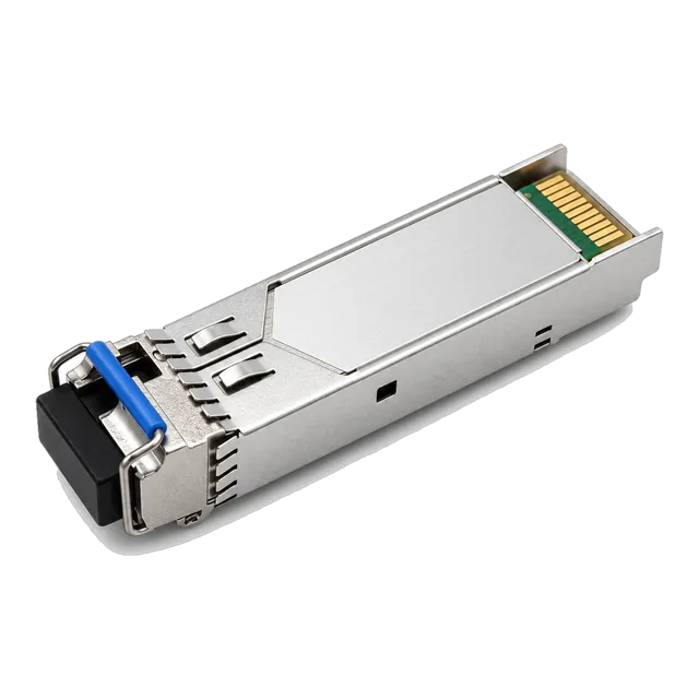
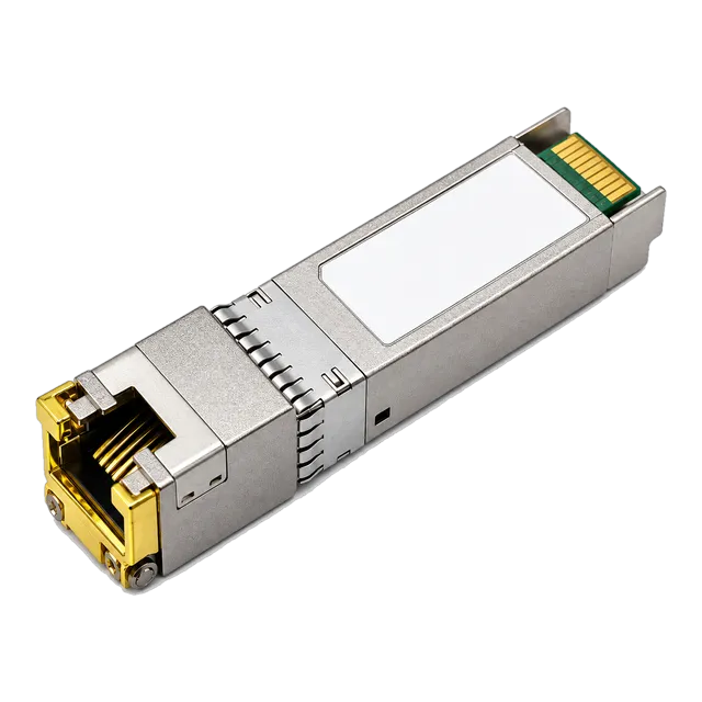
For standard Gigabit fibre aggregation, pairing the switch with a proven 1.25G Gigabit SFP Transceiver ensures full DDM compatibility and link budget reliability. When copper drops are needed inside an optical SFP port, an Affordable 1000BASE-T SFP Copper RJ45 Module provides flexible multi-rate media interconnections.
10Layer 2 access control and switch security hardening
A managed switch protects local access segments by enforcing device authentication, blocking rogue Dynamic Host Configuration Protocol (DHCP) servers, and binding physical ports to authorised MAC addresses. In an unsecured local network, any malicious or misconfigured device can initiate Address Resolution Protocol (ARP) cache poisoning attacks or broadcast rogue IP allocations that disrupt all local hosts.
Managed switches resolve these vulnerabilities by implementing hardware-enforced Layer 2 security suites. Key hardening features include:
- IEEE 802.1X Port-Based Authentication: Interacts with an upstream RADIUS server using Extensible Authentication Protocol (EAP), keeping physical switch ports disabled until the client presents valid certificates or credentials.
- Port Security (MAC Limiting): Restricts the number of dynamic MAC addresses learned on a specific port; exceeding the limit triggers an immediate port shutdown or administrative trap.
- DHCP Snooping: Designates switch ports as "trusted" (uplinks to legitimate DHCP servers) or "untrusted" (downlinks to user endpoints), discarding rogue DHCP Offer packets originating on untrusted access ports.
- Dynamic ARP Inspection (DAI): Validates ARP requests against the DHCP snooping binding database, dropping invalid IP-to-MAC spoofing attempts at wire speed.
11PoE allocation and dynamic power budgeting
Managed switches equipped with Power over Ethernet (PoE) deliver direct-current operating voltage to connected devices alongside Ethernet data over standard Category 5e/6 cabling. Unlike unmanaged PoE injectors that push unmonitored power down the line, a managed switch actively negotiates power delivery using IEEE 802.3af (PoE, up to 15.4W), IEEE 802.3at (PoE+, up to 30W), and IEEE 802.3bt (PoE++, up to 60W or 90W) handshakes.
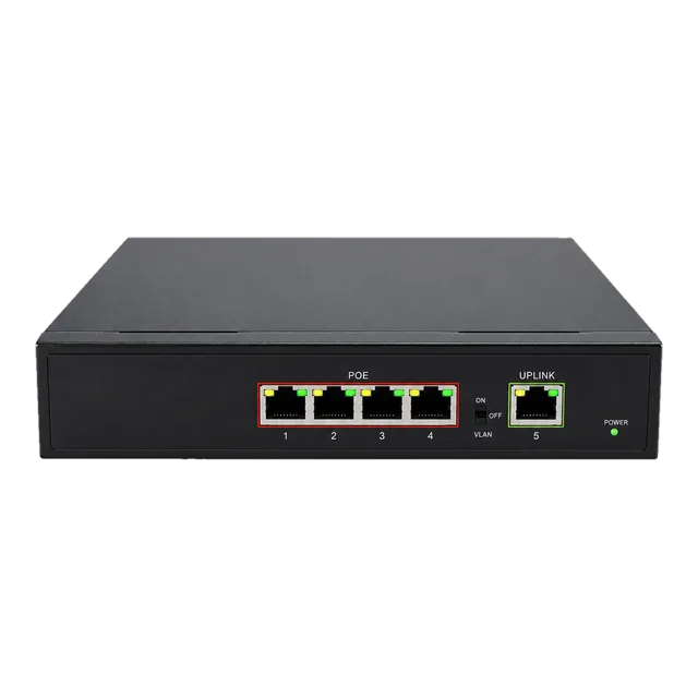
Through administrative interfaces, engineers can configure power classification limits per port, monitor real-time consumption in watts, and schedule power cycles for remote endpoints such as PTZ surveillance cameras or wireless access points. For edge surveillance installations requiring dedicated power delivery, the Gigabit PoE IP Ethernet Switch — 4 PoE Ports + 1 Uplink provides up to 30W per port with built-in power allocation protections. When total attached load exceeds the internal power supply's capacity, the managed switch automatically sheds load from lowest-priority ports to prevent switch reboots. Further guidelines on calculating thermal dissipation and power overhead are detailed in our PoE switch power budget guide.
12Specifying a managed ethernet switch: procurement and RFQ checklist
Procurement teams sourcing a managed ethernet switch must establish rigorous technical specifications in their Request for Quotation (RFQ) documentation to ensure the hardware aligns with exact operational requirements. Relying solely on port count and gigabit ratings frequently results in delivery of under-provisioned switches lacking necessary protocol stacks or environmental hardening.
Ensure your procurement documentation includes the following technical parameters:
- Port Configuration & Line Rates: Number of 10/100/1000BASE-T RJ45 ports and dedicated SFP/SFP+ optical cages (avoid shared "combo" ports if simultaneous operation is required).
- Switching Capacity & Forwarding Throughput: Minimum switching fabric bandwidth (Gbps) and packet forwarding rate (Mpps) calculated for 64-byte minimum frames to confirm non-blocking operation.
- Management & Security Protocol Support: Explicit requirements for SNMPv3, SSHv2, CLI console, IEEE 802.1Q (full 4,094 VLAN range), IEEE 802.1X, DHCP Snooping, and Dynamic ARP Inspection.
- Redundancy & Failover Timers: Support for IEEE 802.1w (RSTP), IEEE 802.1s (MSTP), and sub-50 ms ring protocols (ITU-T G.8032 ERPS) where applicable.
- Physical & Environmental Standards: Operating temperature rating (Commercial 0°C to 50°C vs Industrial -40°C to +85°C), power supply topology (dual redundant DC inputs vs AC mains), and chassis mounting formats (DIN-rail, wall mount, or 19-inch rackmount).
- Optical Diagnostics: Mandatory support for SFF-8472 DDM telemetry on all optical transceiver cages.
For complex deployments or customized switch firmware builds, contact our engineering support team directly at inquiry@optical-module-factory.com for architectural reviews and tailored volume quotation.
13Frequently asked questions
What is the primary difference between a managed switch and an unmanaged switch?
A managed switch provides administrative control over traffic routing, VLAN creation, loop prevention protocols (RSTP/ERPS), and transceiver monitoring. An unmanaged switch operates with a fixed hardware configuration, forwarding all traffic across a single unsegmented broadcast domain without configuration or diagnostic visibility.
Can a smart managed switch replace a fully managed switch?
A smart managed switch can replace a fully managed switch only in smaller, non-critical networks. It provides essential VLANs and QoS via a web GUI, but lacks command-line automation, advanced Layer 3 dynamic routing, SNMP MIB depth, and enterprise authentication like TACACS+.
Why is packet forwarding rate in Mpps important when choosing a managed switch?
Forwarding rate measured in million packets per second (Mpps) defines how quickly the internal ASIC processes minimum-sized 64-byte Ethernet frames. If the Mpps rating is below wire speed, the switch drops packets during heavy network loads or micro-bursts despite having a high gigabit port rating.
How does a managed switch use SFF-8472 digital diagnostic monitoring?
A managed switch reads transceiver memory over an I2C serial bus according to SFF-8472 standards. This provides real-time data on optical transmit power, optical receive power, laser bias current, internal module temperature, and supply voltage, enabling predictive link failure detection.
What is non-blocking switching fabric capacity?
Non-blocking switching capacity means the internal switch backplane bandwidth equals or exceeds the total full-duplex bandwidth of all ports combined. This guarantees that the switch forwards traffic at full wire speed across all ports simultaneously without internal throughput bottlenecks.
Technical review note: confirm model-specific specifications with the product datasheet and the intended host documentation. Product images and application photographs are illustrative.
Discuss this with our team