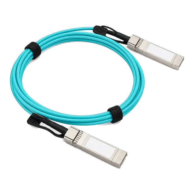
Active optical cables eliminate exposed optical interfaces and link budget calculations by factory-terminating multimode fibre to integrated transceivers, delivering low power consumption, tight bend radiuses, and zero field contamination across 1 to 100 metre runs.
01What are aoc cables and how do they function?
AOC cables are factory-terminated, fixed-length assemblies that integrate optical transceivers directly onto multimode optical fibre to transmit high-speed data across data centre fabrics. An active optical cable converts electrical signals from the host switch or network interface card (NIC) into optical photons within the connector housing using vertical-cavity surface-emitting lasers (VCSELs). The signal traverses 50/125 µm graded-index multimode fibre before a PIN photodiode array at the receiving connector converts the light back into an electrical digital stream conforming to SFF-8431 or SFF-8636 electrical interface standards.
Because the optical interfaces reside entirely inside hermetically sealed connector shells, engineers never handle exposed LC or MPO optical endfaces. This sealed build completely bypasses the dust contamination, optical cleaning protocols, and link budget calculations associated with discrete optical modules. Systems treat the active optical cable as a standard direct-attach connection while gaining the electromagnetic interference (EMI) immunity, light weight, and reach of optical media across high-density aggregation architectures.
02Anatomy of an active optical cable: internal optoelectronics and fiber
Every active optical cable incorporates four core functional components: the electrical connector interface, an optoelectronic conversion engine, micro-optical coupling lenses, and an internal multimode fibre bundle. The electrical connector housing holds an internal printed circuit board (PCB) featuring host-facing gold fingers, an EEPROM chip containing Multi-Source Agreement (MSA) identification data, and a driver/receiver integrated circuit (IC) that conditions the high-speed differential signal.
The electro-optic transmitter utilises an 850 nm VCSEL array powered by an integrated laser driver, which provides temperature-compensated drive currents. On the receiver side, a transimpedance amplifier (TIA) and limiting amplifier process the micro-ampere photocurrent generated by the PIN photodetector into standard host voltage levels. Between the active semiconductors and the OM3 or OM4 optical fibre cores, precision micro-lenses focus the optical paths. A protective polyolefin outer jacket, aramid yarn strength members, and internal bend-insensitive fibre (compliant with ITU-T G.657.A1 or IEC 60793-2-10 category A1a.2/A1a.3) ensure mechanical survival under high-tension cable pulling and tight bend configurations.
03Aoc cables vs direct attach copper (DAC): physical and electrical differences
Choosing between an active optical cable and direct attach copper (DAC) hinges on distance, weight, mechanical flexibility, and airflow impedance in high-density switching racks. Passive direct attach copper uses twinaxial copper conductors (typically 30 AWG to 24 AWG) to transmit high-frequency electrical signals directly between switches without optical conversion, as detailed in our DAC cable engineering guide. While passive DAC produces near-zero latency and requires no power at the connector, copper cables suffer severe high-frequency attenuation, which limits reliable transmission at 25 Gbps or 100 Gbps to approximately 3 to 5 metres.
AOC cables overcome this electrical attenuation by routing optical signals through thin glass cores, sustaining 10 Gbps, 25 Gbps, 40 Gbps, and 100 Gbps streams over lengths reaching 100 metres. A 5-metre 100G passive copper cable weighs roughly 450 grams and measures 7 to 9 mm in outer diameter, whereas an equivalent 100G QSFP28 AOC weighs under 80 grams with an outer diameter of only 3.0 mm. This reduction in physical bulk lowers rack weight loading and eliminates the thermal air dams created by thick copper bundles running across hot-aisle switch exhausts. For a direct procurement comparison of these formats, review our practical guide on DAC or AOC selection criteria.
04Active optical cable vs discrete optical transceivers: operational trade-offs
An active optical cable integrates the transceiver electronics and the optical patch lead into a single permanent assembly, whereas discrete optics rely on independent transceivers joined by separable LC or MPO patch cables. Discrete transceivers, such as standard High Speed 10G SFP+ AOC Active Optical Cable alternatives or optical modules described in our SFP 10G SR transceiver guide, allow structured cabling patching through intermediate distribution frames (IDFs) and patch panels. However, discrete configurations present field vulnerability: dust caps must be pulled, ferrule endfaces inspected with optical microscopes, and scratches polished out.
AOC assemblies eliminate these labour overheads by sealing the optics within factory cleanrooms, achieving lower insertion losses and tighter optical alignment tolerances. Because manufacturers do not need to over-engineer optical launch power to tolerate dirty field-mated connections, AOC optical engines run at lower bias currents. This reduces total power consumption per end by 15% to 25% relative to discrete optical transceiver modules. The primary operational trade-off remains maintenance modularity: if a technician damages an AOC cable sheath, the entire assembly must be replaced, whereas structured systems allow replacing just the patch lead.
05Bit error rate, power consumption, and thermal dynamics in high-density racks
AOC assemblies deliver native pre-forward error correction (pre-FEC) bit error rates (BER) exceeding 1 × 10-15, which easily surpasses the IEEE 802.3 standard baseline requirement of 1 × 10-12. This raw signal integrity stems from matching the VCSEL transmitter, optical fiber core, and receiver circuitry under controlled manufacturing parameters. Signal attenuation along the internal multimode glass is practically negligible over short data centre runs (approximately 3.0 dB/km at 850 nm), meaning cable length variations from 1 metre to 30 metres generate negligible jitter or insertion degradation.
Thermal dissipation remains a critical advantage in 1RU top-of-rack (ToR) leaf switches operating with 32, 48, or 64 ports. A standard 100GBASE-SR4 discrete optical transceiver typically consumes between 2.5 W and 3.5 W per port, yielding up to 224 W of pure optical transceiver heat in a 64-port switch. A 100G QSFP28 active optical cable operates at approximately 1.8 W to 2.2 W per end. This 30% reduction in thermal envelope lowers internal switch die temperatures, reduces cooling fan duty cycles, and stabilises MTBF (Mean Time Between Failures) metrics across enterprise server cabinets.
06Transmission distances and multimode fiber grades (OM3, OM4, OM5)
The maximum functional reach of an active optical cable depends on the internal multimode fibre grade and the signalling rate of the host transceivers. Multimode fibre is categorised by its effective modal bandwidth (EMB), measured in MHz·km at 850 nm. High-bandwidth optical cores prevent intermodal dispersion, which occurs when distinct light modes travel along the core at varying velocities and cause pulse spreading at high baud rates.
| Fibre Grade | Core / Cladding Diameter (µm) | Overfilled Launch Bandwidth (MHz·km) | Effective Modal Bandwidth (MHz·km) | Max Reach @ 10 Gbps (m) | Max Reach @ 25 Gbps / 100 Gbps (m) |
|---|---|---|---|---|---|
| OM2 | 50 / 125 | 500 | Not Rated | 82 | Not Recommended |
| OM3 | 50 / 125 | 1500 | 2000 | 300 | 70 |
| OM4 | 50 / 125 | 3500 | 4700 | 400 | 100 |
| OM5 | 50 / 125 | 3500 | 4700 (850 nm) / 2470 (953 nm) | 400 | 100 (Optimised for SWDM) |
Standard commercial AOC assemblies deploy OM3 fibre for cost-effective lengths up to 20 or 30 metres, switching to OM4 for extended runs between 30 and 100 metres. While OM5 accommodates short wavelength division multiplexing (SWDM4), OM4 remains the primary industry standard for high-speed single-wavelength VCSEL arrays operating at 850 nm across standard Ethernet architectures.
07Bend radius, cable management, and tensile limits of active fiber cable
Maintaining the structural integrity of an active fiber cable requires strict adherence to dynamic and static bend radius limits to prevent micro-bending and macro-bending attenuation. When glass cores bend past their critical angle, higher-order optical modes radiate outward into the cladding, triggering immediate packet dropouts. AOC cables incorporate bend-insensitive multimode fibre (BIMMF) with a refractive index trench around the core, keeping light trapped even during sharp turns.
The mechanical operational thresholds for standard AOC assemblies conform to the following engineering parameters:
- Static bend radius (installed): 30 mm minimum (or 10× outer cable diameter).
- Dynamic bend radius (installation routing): 60 mm minimum (or 20× outer cable diameter).
- Maximum pulling tension: 150 N (approx. 15 kg force) during pathway pulling. Excessive pulling force transfers strain to internal micro-optical bonds, causing permanent transmitter misalignment.
- Crush resistance: 1000 N / 100 mm short-term; mechanical protection requires avoiding direct clamping under metal zip-ties. Use hook-and-loop (Velcro) straps exclusively.
08Form factors: SFP+, SFP28, QSFP+, QSFP28, and breakout configurations
AOC cables are manufactured across multiple physical form factors defined by the Small Form Factor Committee (SFF) to accommodate generational data rates and leaf-spine architectures. SFP+ assemblies provide single-lane 10 Gbps connectivity governed by SFF-8431, while SFP28 extends the physical housing to support 25 Gbps transmission via 28 Gbps NRZ modulation defined in SFF-8402 and IEEE 802.3by.
For higher aggregation nodes, four-channel form factors dominate:
- 40G QSFP+ AOC: Houses 4 × 10 Gbps lanes conforming to SFF-8436, operating over an 8-fibre multimode optical ribbon.
- 100G QSFP28 AOC: Utilises 4 × 25 Gbps lanes per SFF-8665, running over internal OM4 ribbon cable. For architectural planning at these data rates, explore our technical guide on planning 100G SR4 multimode links.
- Breakout AOC assemblies: Feature an aggregation head on one side (such as a 100G QSFP28) splitting into four discrete tails (such as 4 × 25G SFP28). An optical transition block houses the physical breakout joint, allowing network architects to connect high-radix spine ports directly to 25G compute nodes without separate breakout cassettes.
09Worked calculation: power dissipation and weight savings across a 42U rack
Installing high-density active assemblies generates measurable financial and physical improvements in power dissipation, structural weight, and thermal cooling loads compared to passive copper or discrete optical modules. Consider a standard 42U rack containing two ToR switches with 48 server downlinks each, requiring 96 total cross-rack interconnects at 25 Gbps over an average cable length of 5 metres.
Parameters for Comparison:
- Option A: 25G Direct Attach Passive Copper (30 AWG, 5 m). Cable weight: 0.32 kg per assembly. Power per port: 0.1 W. Outer diameter: 6.2 mm.
- Option B: 25G Discrete Transceivers (2 × 25GBASE-SR modules + 5 m OM4 duplex patch cord). Module weight: 0.04 kg × 2; cable weight: 0.04 kg (Total 0.12 kg). Power per port: 1.2 W × 2 = 2.4 W per link.
- Option C: 25G SFP28 Active Optical Cable (5 m OM4). Cable weight: 0.08 kg per assembly. Power per link: 0.8 W total (0.4 W per end). Outer diameter: 3.0 mm.
Total Cable Weight Calculation:
- Copper Weight: 96 × 0.32 kg = 30.72 kg in the cable arm.
- AOC Weight: 96 × 0.08 kg = 7.68 kg in the cable arm.
- Result: AOC reduces the overhead cable tray mechanical load by 23.04 kg (a 75% structural weight reduction).
Thermal Power Dissipation Calculation:
- Discrete Optics Power: 96 links × 2.4 W = 230.4 W dissipated inside the switch chassis.
- AOC Power: 96 links × 0.8 W = 76.8 W dissipated inside the switch chassis.
- Result: AOC reduces rack thermal loading by 153.6 W. Over an operational year (8,760 hours), this yields a direct electricity reduction of 1,345.5 kWh per rack, excluding additional savings from reduced computer room air handler (CRAH) refrigeration workloads.
10Decision table: selecting between DAC, AOC, and optical transceivers
Selecting the optimal physical medium requires balancing distance, capital expenditure, power availability, and operational environment constraints. The following engineering matrix outlines the specific deployment envelope for each high-speed interconnect technology:
| Interconnect Technology | Reach (m) | Power / Port (W) | Latency (ns) | Cable Diameter (mm) | EMI Immunity | Relative Cost |
|---|---|---|---|---|---|---|
| Passive DAC | 0.5 – 3.0 (at 25G/100G) | < 0.1 | < 10 | 6.0 – 11.0 | Moderate | Low |
| Active Copper (ACC) | 3.0 – 7.0 | 0.5 – 1.5 | < 20 | 5.5 – 8.5 | Moderate | Medium |
| AOC (Active Optical) | 1.0 – 100.0 | 0.6 – 2.2 | ~ 15 – 30 | 3.0 – 4.0 | Immune | Medium |
| Discrete SR Transceiver | 0.5 – 100.0 (OM4) | 1.2 – 3.5 | ~ 15 – 30 | 2.0 – 3.0 (Patch) | Immune | High |
| Discrete LR Transceiver | Up to 10,000 | 2.5 – 4.5 | ~ 20 – 35 | 2.0 – 3.0 (SMF) | Immune | Very High |
Active optical cables represent the primary engineering choice for cross-rack, inter-row (middle-of-row and end-of-row), and high-density compute interconnects where copper exceeds distance or weight limits, and structured optics add unnecessary operational complexity.
11EEPROM programming, MSA compliance, and multi-vendor host coding
Both ends of an active optical cable contain an integrated microcontroller with EEPROM memory structured in compliance with SFF-8472 (for SFP/SFP28) or SFF-8636 (for QSFP+/QSFP28) specifications. This memory structure informs host network operating systems (NOS) regarding transceiver type, maximum link length, vendor identification, part numbering, serialisation, and laser drive parameters. If the EEPROM registers fail to match the host platform's internal security tables, the port will flag an unsupported transceiver alarm and disable the link.
Because active optical cables directly bridge two discrete pieces of hardware, engineers frequently require multi-vendor coding on a single assembly. For instance, linking a server equipped with a generic NIC to an enterprise aggregation leaf switch requires coding End A with generic MSA parameters and End B with proprietary vendor-specific microcode and checksum calculations. MARS provides customised multi-vendor EEPROM programming across our catalogue of DAC & AOC Cable assemblies to ensure uncompromised interoperability across heterogeneous switching environments.
12Active fiber optic cable testing and link diagnostics (DDM/DOM realities)
Digital Diagnostic Monitoring (DDM), alternatively termed Digital Optical Monitoring (DOM), functions differently inside an active fiber optic cable than inside discrete optical transceivers. SFF-8472 and SFF-8636 standards define five core operational metrics: internal module temperature, operating supply voltage, laser bias current, optical transmit power (Tx), and optical receive power (Rx). In discrete optical transceivers, continuous monitoring of Tx and Rx power allows technicians to pinpoint optical connector attenuation and calculate link margin degradation.
In standard AOC assemblies, optical transmit and receive paths are sealed and fixed at the factory. Consequently, many AOC controller microchips provide full monitoring for temperature, operating voltage, and laser bias current, but may report static or dummy values for optical Tx and Rx power via the command-line interface (CLI). When validating active assemblies in the lab, testing must rely on real-time Bit Error Rate Testers (BERT) with pseudorandom binary sequence (PRBS31) stress testing, frame loss analysis, and eye-diagram validation rather than optical power meters.
13Technical RFQ specification checklist for active optical cable aoc procurement
Engineers preparing a request for quotation (RFQ) for an active optical cable aoc deployment must specify exact operational and physical requirements to prevent interoperability failures. Copy and apply this technical checklist during the procurement scoping phase:
- Data Rate and Protocol: Define the baseline signalling standard (e.g., 10GBASE-AOC, 25GBASE-AOC per IEEE 802.3by, 100GBASE-AOC per IEEE 802.3bm, or InfiniBand EDR/HDR).
- Form Factor Configuration: Specify straight (SFP28-to-SFP28, QSFP28-to-QSFP28) or breakout assemblies (QSFP28 to 4 × SFP28) along with the breakout breakout-tail length split (standard: 0.5 m).
- Physical Length: Measure precise inter-rack routing paths including cable management arms, adding 0.5 metres of service loop slack. Standard AOC lengths: 1 m, 2 m, 3 m, 5 m, 7 m, 10 m, 15 m, 20 m, 30 m, 50 m, 100 m.
- Fibre Jacket Flame Rating: Specify OFNP (Plenum) for overhead air-handling plenums, OFNR (Riser) for vertical shafts, or Low Smoke Zero Halogen (LSZH) for European building code compliance.
- Host Platform Vendor Coding: List the exact switch and NIC models on both ends (End A vendor/model and End B vendor/model) to mandate pre-shipment EEPROM flashing.
- Operating Temperature Grade: Standard commercial grade (0°C to +70°C) for climate-controlled data centres, or industrial grade (-40°C to +85°C) for edge cabinets.
14Specifying and deploying aoc cables in your fabric
To execute a successful rollout of active optical cables across your enterprise network or data centre fabric, finalize your physical routing pathways and cable lengths using physical mock-ups before placing production orders. Active optical cables cannot be cut, field-terminated, or respliced; ordering an assembly that is 50 centimetres too short stalls deployment, while excess length forces bulky service loops that obstruct rack airflow. Cross-reference your intended cable runs against our interactive tools, such as the transceiver and cable selector, to match switch architectures with validated physical assemblies.
If your deployment involves heterogeneous switching fabrics requiring dual-personality EEPROM coding, consult our applications engineering team directly. Submit your port mapping specifications and hardware inventory through our contact page or reach out via WhatsApp at +86 176 2154 1688 to arrange lab testing, sample evaluations, and pre-programmed validation units tailored to your production leaf-spine topology.
15Frequently asked questions
What is the difference between DAC and AOC cables?
Direct attach copper (DAC) cables use copper twinaxial wires to transmit electrical signals over short distances (up to 5 metres), consuming almost no power. AOC cables use optical multimode fibre with integrated transceivers to convert electrical signals to light, enabling low-weight, flexible links up to 100 metres with complete EMI immunity.
Can active optical cables be cut and re-terminated in the field?
No, active optical cables cannot be cut, spliced, or field-terminated. The multimode optical fibres are permanently aligned and sealed inside the connector housing with micro-lenses and optoelectronic components during factory manufacturing. Any mechanical cut destroys the internal optical circuits, requiring full assembly replacement.
Do AOC cables generate more heat than copper DACs?
Yes, AOC cables consume more power than passive DAC cables because their integrated transceivers require electrical energy to drive VCSEL lasers and transimpedance amplifiers. An active optical cable typically consumes between 0.6 W and 2.2 W per end, whereas a passive copper DAC consumes less than 0.1 W total.
Why use an active optical cable instead of optical transceivers and patch cords?
AOC cables eliminate exposed optical connectors, removing the risk of optical dust contamination and the need for inspection microscopes or cleaning pens. They provide lower power consumption, reduce overall link cost, and simplify inventory management by integrating the cable and transceivers into a single, pre-tested part number.
Can an AOC cable connect two switches from different manufacturers?
Yes, active optical cables can connect switches from different manufacturers if the cable is programmed with dual-vendor compatibility. The EEPROM microchip at End A is coded to match the first switch vendor, while End B is coded with the specific firmware profile required by the second host platform.
Technical review note: confirm model-specific specifications with the product datasheet and the intended host documentation. Product images and application photographs are illustrative.
Discuss this with our team