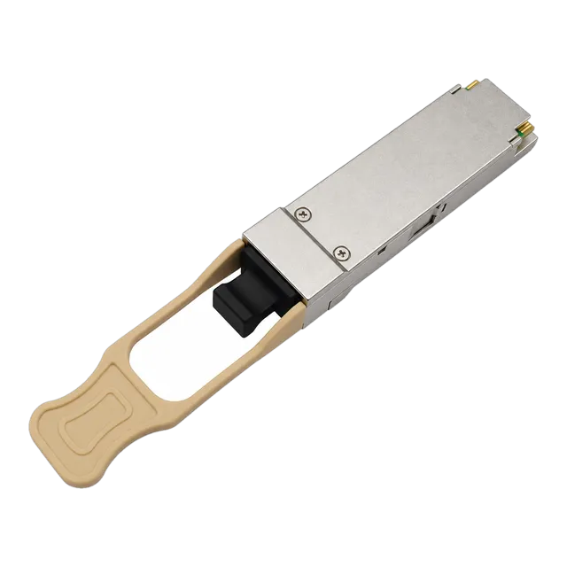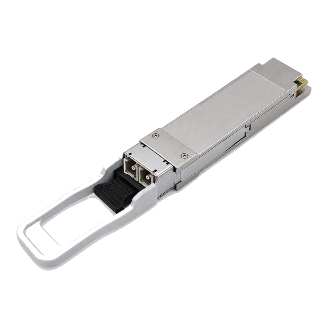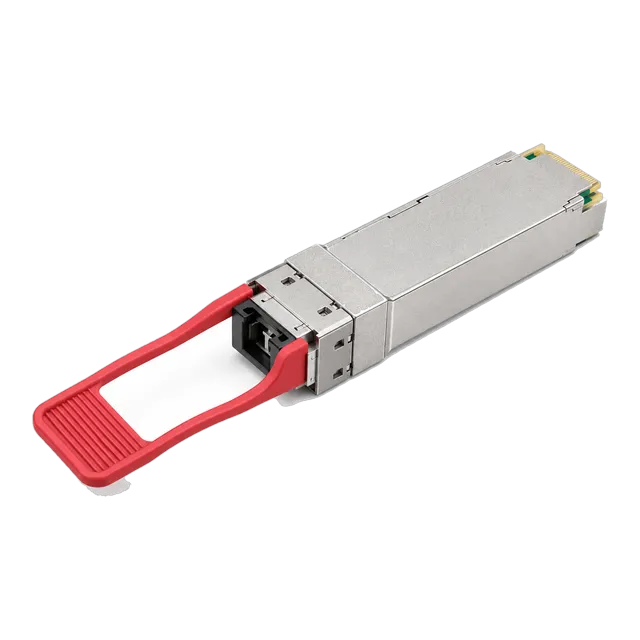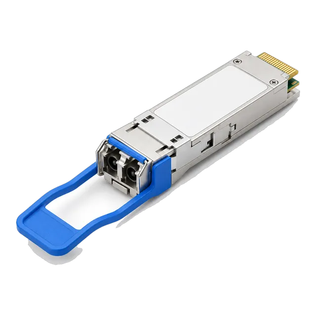
Selecting the right QSFP28 transceiver requires matching host RS-FEC requirements, lane architecture, and insertion loss limits to the cable plant, preventing costly interface mismatches and ensuring reliable 100 Gbps line-rate operation across modern data centre switches.
01What is a QSFP28 transceiver?
A qsfp28 transceiver is a hot-pluggable optical or electrical interface module designed for 100 Gigabit Ethernet (100GbE), InfiniBand EDR, and 32G/128G Fibre Channel applications. Engineered to handle four differential electrical lanes transmitting at up to 28 Gbps each, the Quad Small Form-factor Pluggable 28 (QSFP28) package delivers aggregate throughput of 103.125 Gbps for standard Ethernet framing. Governed mechanically and electrically by the SFF-8665 and SFF-8636 multi-source agreements (MSA), the form factor preserves the compact footprint of earlier 40G QSFP+ designs while delivering a 250 percent increase in interface density across networking switch faceplates.
Network architects deployed in enterprise aggregation and hyperscale leaves rely on 100G QSFP28 transceivers because they reduce per-gigabit power draw compared to older CFP, CFP2, and CFP4 form factors. The electrical host interface relies on four transmitter and receiver pairs defined by IEEE 802.3bm CAUI-4 (Chip-to-Chip and Chip-to-Module). Inside the package, high-density optical assemblies route signals using Vertical-Cavity Surface-Emitting Lasers (VCSEL) or Distributed Feedback (DFB) lasers, converting electrical differential signals into optical pulses with negligible latency.
02How do 100G QSFP28 optical interfaces function?
A 100G QSFP28 optical interface functions by multiplexing four discrete 25 Gbps channels across optical fibre infrastructure or by transmitting high-order PAM4 modulations over single wavelengths. In four-lane optics such as 100GBASE-SR4 and 100GBASE-LR4, the host sends four 25.78125 Gbps Non-Return-to-Zero (NRZ) electrical streams over the 38-pin connector. The internal driver circuitry stabilises the signals before feeding laser arrays. Laser signals travel either across parallel ribbon fibres or through integrated optical multiplexers that combine four distinct wavelengths onto a single glass strand.
At the receiving end, incoming optical carriers are either separated by passive optical demultiplexers or collected across parallel photodiode detectors. Transimpedance amplifiers (TIA) convert the optical signals back into CAUI-4 electrical waveforms. Unlike legacy serial transmission, modern 100g optics leverage Digital Diagnostics Monitoring (DDM) per SFF-8636, permitting real-time telemetry extraction for internal temperature, laser bias current, supply voltage, and per-lane optical transmit/receive power values.
03Is a 100 gig SFP the same as a QSFP28 module?
A 100 gig SFP is not identical to a QSFP28 module, although network teams colloquialise both terms when discussing 100G switch ports. In optical terminology, "SFP" refers to single-lane Small Form-factor Pluggable architectures, such as SFP+ (10G) and SFP28 (25G). Conversely, QSFP designates "Quad" architecture running four parallel electrical lanes. While experimental single-lane 100G SFP112 interfaces exist, practically all current enterprise and service provider switches standardise on the 100g qsfp28 footprint to provide backward physical compatibility with legacy QSFP ports.
Confusion frequently arises when engineers compare 100 g sfp references against dual-rate SFP28 sockets. A switch chassis provisioned with native QSFP28 cages cannot physically accept an SFP-form-factor module without a mechanical QSA (QSFP-to-SFP) carrier adapter. Understanding pin layout constraints and physical dimensions prevents serious ordering mistakes during procurement cycles. SFF specifications outline precise mechanical geometries: a standard QSFP28 measures approximately 18.35 mm wide by 8.5 mm high, whereas an SFP28 module measures only 13.4 mm wide by 8.5 mm high.
04What are the common 100G transceivers optical standards?
Common 100g transceivers adhere to distinct IEEE 802.3 and industry MSA standards categorised by transmission reach, fibre type, and optical channel multiplexing. Multimode short-reach runs rely on IEEE 802.3bm 100GBASE-SR4, using 850 nm VCSEL arrays over parallel multimode fibre (MMF) terminated on MPO-12 connectors. For campus backbones and metropolitan links up to 10 km, IEEE 802.3ba 100GBASE-LR4 multiplexes four LAN-WDM wavelengths (1295.56 nm, 1300.05 nm, 1304.58 nm, and 1309.14 nm) across single-mode fibre (SMF) via duplex LC connectors.
Between these boundaries, the CWDM4 MSA fills intermediate 2 km requirements using four Coarse Wavelength Division Multiplexing channels (1271 nm, 1291 nm, 1311 nm, and 1331 nm) without active thermoelectric coolers (TEC), substantially lowering module thermal dissipation. For enterprise links bridging short distances, models like the 100G QSFP28 SR4 100m module provide baseline high-density intra-rack coupling, whereas extended enterprise sites utilise the 100G QSFP28 eZR4 100km transceiver equipped with integrated Semiconductor Optical Amplifiers (SOA) to span inter-city networks.
05Comparing 100G QSFP28 optical specifications
Comparing optical parameters across standard MSA transceiver families reveals significant variations in wavelength allocation, power consumption, and link margins. The table below outlines production performance baselines for mainstream QSFP28 module types deployed in enterprise data centres and telecommunication points of presence.
| Standard | Fibre Type | Wavelength (nm) | Connector | Max Reach (m) | Tx Power (dBm) | Rx Sens. (dBm) | Max Power (W) |
|---|---|---|---|---|---|---|---|
| 100GBASE-SR4 | OM4 MMF | 850 | MPO-12 (Base-8) | 100 | -8.4 to +2.4 | -10.3 | 2.5 |
| 100G-CWDM4 | OS2 SMF | 1271–1331 | Duplex LC | 2,000 | -6.5 to +2.5 | -10.0 | 3.5 |
| 100G-PSM4 | OS2 SMF | 1310 | MPO-12 | 500 | -9.4 to +2.0 | -12.66 | 2.5 |
| 100GBASE-LR4 | OS2 SMF | 1295–1309 (LAN-WDM) | Duplex LC | 10,000 | -4.3 to +4.5 | -10.6 | 3.5 |
| 100GBASE-ER4-Lite | OS2 SMF | 1295–1309 (LAN-WDM) | Duplex LC | 40,000 | -0.5 to +4.5 | -19.0 | 4.5 |
| 100G-eZR4 | OS2 SMF | 1295–1309 (SOA) | Duplex LC | 100,000 | 0.0 to +4.0 | -28.0 | 5.5 |
Engineers evaluating these formats must account for transceiver thermal dissipation. While an SR4 module functions comfortably within a 2.5 W budget, long-reach modules incorporating LAN-WDM lasers and SOAs generate upwards of 4.5 W to 5.5 W. Switch fan profiles and chassis airflow paths must accommodate these higher heat loads to avoid thermal throttling and packet drops across front-panel ports.
06How does RS-FEC impact 100G optical links?
Reed-Solomon Forward Error Correction (RS-FEC) impacts 100G optical links by correcting bit transmission errors before they trigger packet retransmissions, expanding acceptable physical layer link budgets. Defined under IEEE 802.3 Clause 91, RS(528,514) FEC inspects data blocks and corrects up to 7 symbol errors per 528-symbol codeword. The application of RS-FEC improves the pre-FEC Bit Error Ratio (BER) threshold from a strict 10^-12 baseline down to 5x10^-5, enabling transceivers to operate reliably across noisy, high-loss optical channels.
For 100GBASE-SR4 and 100G-CWDM4 variants, host-side RS-FEC is mandatory. If one switch port has Clause 91 FEC enabled while the link partner port disables it or defaults to Clause 74 FireCode FEC, the interface remains down at the physical coding sublayer (PCS) despite full optical power readings on DDM. When drafting RFQ documents, network engineers must specify host platform FEC capability to ensure interoperability between dissimilar network operating systems.
07Calculating a 100GBASE-LR4 optical link budget
Calculating a 100GBASE-LR4 link budget verifies whether transmitter launch power minus channel insertion losses provides adequate margin above receiver sensitivity. Consider an 8.5 km campus link run over ITU-T G.652.D single-mode fibre with four intermediate patch panels (eight mated LC connector pairs) and two fusion splices. We calculate total optical margin using standard loss parameters defined by TIA-568.3-D and IEEE 802.3ba Table 88-7.
The mathematical evaluation executes through the following parameters:
- Transmitter Minimum Optical Output Power (P_tx_min): -4.3 dBm per lane
- Receiver Sensitivity at Stressed BER (P_rx_sens): -10.6 dBm per lane
- Total Available Optical Power Budget (OPB): (-4.3 dBm) - (-10.6 dBm) = 6.3 dB
- Fibre Attenuation at 1310 nm: 8.5 km × 0.35 dB/km = 2.975 dB
- Connector Loss: 8 mated pairs × 0.50 dB/pair (TIA standard) = 4.00 dB
- Splice Loss: 2 fusion splices × 0.10 dB/splice = 0.20 dB
- Total Channel Insertion Loss (CIL): 2.975 dB + 4.00 dB + 0.20 dB = 7.175 dB
Evaluating the margin: Margin = OPB - CIL = 6.3 dB - 7.175 dB = -0.875 dB. This calculation reveals an optical deficit of 0.875 dB, confirming the standard link will fail or encounter packet degradation over time. To resolve this, high-grade low-loss LC patch panels rated at 0.20 dB per mated pair must be installed (lowering connector losses to 1.60 dB, yielding a healthy 1.525 dB safety margin), or engineers must deploy a link budget calculator to reassess whether ER4-Lite optics are required.
08What are the MPO connector polarity rules for 100G SR4?
MPO connector polarity rules for 100GBASE-SR4 establish correct optical coupling between the four transmitter VCSEL lanes on one module and the four receiver photodiodes on the remote peer. Under TIA-568-C.3 standards, 100GBASE-SR4 employs an MPO-12 optical interface operating in Base-8 mode. The outer four positions (lanes 1 to 4) transmit, the central four positions (lanes 5 to 8) remain unpopulated, and the opposite outer four positions (lanes 9 to 12) receive optical signals.
Maintaining link orientation requires strict cable management protocols across structured patching infrastructure:
- Deploy Method B (Type-B) polarity trunks featuring Key-Up to Key-Up MPO female connectors to execute the mandatory 1-to-12 lane crossover automatically.
- Ensure MPO patch cords connecting transceivers are unpinned (female), mating safely against the guide pins inside the QSFP28 internal optical receptacle.
- Never connect pinned cables directly into optical modules, as exposed metal alignment pins will destroy internal optical ceramic ferrule blocks.
- Inspect MPO end-faces with an automated optical microscope before insertion, verifying that dust particles do not block the active Base-8 transmit lanes.
Reviewing our detailed MPO Base-8 polarity guide assists cabling engineers during patch field installation.
09When should you choose 100G BiDi over dual-fibre optics?
You should choose 100G BiDi (Bidirectional) optics when structured single-mode or multimode cabling runs lack spare fibres, making single-strand bidirectional multiplexing essential to double existing facility density. Instead of using separate fibres for transmit and receive directions, BiDi transceivers employ internal Wavelength Division Multiplexing (WDM) diplexers that combine two counter-propagating light signals onto one optical strand. This architecture cuts physical cabling costs across leased dark fibre or high-occupancy data centre riser ducts.
For enterprise single-mode links traversing distances from 10 km to 40 km, transceivers like the 100G BiDi QSFP28 LR1/ER1 single-fibre module use internal optical diplexers running PAM4 encoding. This enables full 100 Gbps line rates across a simplex LC connection. For multimode infrastructure, dual-wavelength BiDi transceivers use 850 nm and 908 nm over standard OM4 duplex LC fibre, bypassing costly migrations to parallel MPO-12 trunk cables.
10How do 100G optics compare to 40G QSFP+ modules?
A 100G optical transceiver quadruples data plane throughput while maintaining identical faceplate density compared to legacy 40G QSFP+ optics. A standard 40G QSFP+ module, governed by IEEE 802.3ba 40GBASE-SR4 or LR4, routes four lanes at 10.3125 Gbps using NRZ modulation. In contrast, a 100G QSFP28 transceiver operates its internal lanes at 25.78125 Gbps. Despite this 2.5x density improvement, the electrical interface of QSFP28 fits within the identical mechanical form factor.
Many top-of-rack (ToR) data centre switches incorporate dual-speed physical cages. If a network engineer inserts a legacy 40G module such as a 40G QSFP+ transceiver into a QSFP28 cage, the host switch reconfigures its internal clock and data recovery (CDR) circuits to 10G per lane, establishing a stable 40GbE link. However, a 100G module will not synchronize if connected to a native 40G QSFP+ host socket, as the older host bus logic cannot clock up to 25.78 Gbps signaling rates.
11Can a 100G QSFP28 port break out to 4x 25G SFP28?
A 100G QSFP28 port can break out to 4x 25G SFP28 ports when the host switch hardware supports channelised port splitting and appropriate breakout cabling is installed. Because the native internal structure of a 100GBASE-SR4 or 100GBASE-PSM4 optic consists of four autonomous 25.78125 Gbps NRZ lanes, switch operating systems can reconfigure the PHY layer to treat the cage as four independent 25G interfaces. This configuration commonly aggregates server NIC downlinks into central spine-leaf fabrics.
Breakout architectures function through two primary physical implementations:
- Direct MPO-to-4x-Duplex-LC fanout assemblies running from a multimode 100G SR4 module directly into discrete server-side SFP28 SR optics.
- Passive Direct Attach Copper (DAC) breakout splitter cables, routing high-speed twinaxial pairs directly from a single QSFP28 plug to four separate SFP28 connectors.
- Active Optical Breakout Cables (AOC) with factory-integrated active optoelectronics for intermediate distances across adjacent server racks.
Consult our reference on transceiver EEPROM coding to verify that host interfaces process channelised link declarations properly.
12How to verify QSFP28 DDM diagnostics and troubleshooting
Verifying QSFP28 Digital Diagnostics Monitoring (DDM) provides visibility into optical module physical health, preventing link outages through continuous telemetry evaluation. Specified within SFF-8636, DDM enables the switch operating system to report real-time operating metrics across I2C memory register addresses. Reading these diagnostics through the switch command line interface (CLI) identifies optical faults before physical hardware damage occurs.
Key diagnostic metrics include:
- Optical Receive Power (Rx Power): Monitored per channel in dBm or mW. Values approaching the receiver sensitivity floor (-10.3 dBm on SR4) signal dirty end-faces, macrobends, or high connector insertion losses.
- Optical Transmit Power (Tx Power): Demonstrates the health of internal laser diodes. Drastic drops indicate VCSEL or DFB degradation caused by electrical overstress or aging.
- Laser Bias Current: Reported per lane in milliamperes (mA). If internal control loops spike bias current to sustain nominal optical output, laser failure is imminent.
- Module Operating Temperature: Internal case temperature in degrees Celsius. Standard commercial modules must remain between 0 °C and 70 °C; exceeding 70 °C causes bit errors and activates automatic thermal shutdown circuits.
- VCC Internal Supply Voltage: Validates clean 3.3 V host power rail delivery. Variances beyond ±5% point to host power distribution faults.
13Procurement checklist for bulk 100G optical transceivers
Standardising a technical bill of materials (BOM) prevents deployment failures caused by incompatible transceiver firmware, connector mismatches, and power threshold discrepancies. System integrators and data centre procurement teams should reference the following engineering checklist prior to issuing Requests for Quotation (RFQs) for high-density 100G optics.
| Verification Checkpoint | Target Technical Specification | Sign-Off Criterion |
|---|---|---|
| Form Factor & Standard | QSFP28 (SFF-8665, SFF-8636) | Complies with target IEEE standard (e.g., 100GBASE-SR4, LR4, CWDM4). |
| Optical Media & Connector | MMF (OM4) or SMF (G.652.D) | MPO-12 (Base-8, unpinned) or Duplex LC; verified end-face polish (UPC/APC). |
| Host Platform Encoding | Target Vendor EEPROM Map | Correct Multi-Source Agreement Table 00/01/02 coding for host acceptance. |
| RS-FEC Requirements | IEEE 802.3 Clause 91 RS(528,514) | Host OS supports mandatory FEC matching module transmitter specifications. |
| Thermal Rating | Commercial (0 to 70 °C) or Industrial (-40 to 85 °C) | Thermal profile verified against chassis airflow and switch environment. |
| Power Budget Margin | Minimum 2.0 dB channel safety margin | Calculated link budget accounts for passive panel losses and cable attenuation. |
| DDM Telemetry Support | SFF-8636 Compliance | Full CLI visibility of Tx/Rx power, bias current, temperature, and supply rail. |
To examine structured procurement workflows, review our guide on optical procurement checklists before ordering high-density optical hardware.
14How to order and deploy QSFP28 optical modules reliably
Ordering and deploying QSFP28 optical modules reliably requires coordinating exact host switch compatibility codes with verified optical link budgets. Before submitting volume procurement orders, cross-reference host network operating system requirements against specific MSA EEPROM configuration maps. SFF-8636 memory mapping defines specific vendor identifier blocks; incorrect serialization or checksum values can cause host operating systems to reject third-party transceivers or flag non-fatal interface warnings.
For complex network deployments involving diverse top-of-rack switches, service provider edge platforms, and multi-tenant compute nodes, Shanghai Mars Industrial Co., Ltd. supplies high-density 100G QSFP28 optical transceivers across commercial and industrial temperature profiles. Modules undergo full platform validation, testing for bit error rate floors and DDM telemetry integration before dispatch. Contact our engineering team at optical-module-factory.com or via email at inquiry@optical-module-factory.com to request sample units, verify switch compatibility profiles, or obtain link loss calculations for custom fibre topologies.
15Frequently asked questions
What is the maximum reach of a 100G QSFP28 transceiver?
Maximum transmission reach depends directly on the optical standard and fibre type deployed. Multimode 100GBASE-SR4 links achieve 70 metres over OM3 and 100 metres over OM4. Single-mode options range from 2 km for CWDM4 and 10 km for 100GBASE-LR4 up to 40 km for ER4-Lite and 100 km for amplified eZR4 configurations.
Can you plug a 40G QSFP+ module into a 100G QSFP28 port?
Yes, standard 100G QSFP28 switch cages provide physical and mechanical backward compatibility with 40G QSFP+ transceivers. When a 40G module is inserted, the host switch down-clocks the interface from 25 Gbps to 10 Gbps per lane, negotiating a standard 40GbE connection provided the switch operating system firmware supports dual-rate switching.
Why is RS-FEC mandatory on 100GBASE-SR4 optics?
IEEE 802.3bm mandates Reed-Solomon Forward Error Correction (RS-FEC Clause 91) for 100GBASE-SR4 because high-speed 25.78 Gbps VCSEL transmission introduces higher bit error rates. RS-FEC corrects up to 7 symbol errors per 528-symbol block, shifting an operational pre-FEC BER of 5x10^-5 to a clean post-FEC BER exceeding 10^-12.
What connector does a 100G QSFP28 SR4 transceiver use?
A 100GBASE-SR4 transceiver uses an unpinned (female) MPO-12 connector operating in Base-8 mode. Optical transmission uses the four outermost left lanes, while the four outermost right lanes receive incoming light. The central four fiber positions remain dark, requiring Type-B female-to-female MPO cables to maintain proper polarity.
How does 100G CWDM4 differ from 100G PSM4?
100G-CWDM4 multiplexes four distinct optical wavelengths onto one duplex single-mode LC fibre pair using internal optical filters, covering reaches up to 2 km. In contrast, 100G-PSM4 transmits unmultiplexed 1310 nm signals across eight parallel single-mode fibres terminated on an MPO-12 connector, restricting maximum supported links to 500 metres.
What is the power consumption of a standard 100G QSFP28 module?
Standard 100G QSFP28 power consumption ranges from 2.5 W to 5.5 W depending on design. Short-reach multimode SR4 optics typically draw under 2.5 W. Uncooled single-mode CWDM4 optics consume roughly 3.5 W, whereas long-reach LAN-WDM modules like LR4 and ER4-Lite draw between 3.5 W and 5.0 W to power internal thermoelectric coolers.
Technical review note: confirm model-specific specifications with the product datasheet and the intended host documentation. Product images and application photographs are illustrative.
Discuss this with our team