Selecting a 10Gb Ethernet switch requires balancing port PHY physical media between low-latency 10G SFP+ optical cages and versatile 10GBASE-T copper ports while verifying non-blocking switching fabric bandwidth and per-port transceiver thermal dissipation.
0110Gb Ethernet switch architecture and baseline capabilities
A 10Gb Ethernet switch provides Layer 2 or Layer 3 packet forwarding at a nominal line rate of 10.3125 Gbps per port using 64b/66b line coding defined in IEEE 802.3ae. Selecting a 10gb ethernet switch requires evaluating whether your network topology demands native optical Small Form-Factor Pluggable Plus (SFP+) cages, integrated 10GBASE-T twisted-pair copper interfaces, or a hybrid combination. In enterprise aggregation, campus backbones, and server access layers, deploying a ten gigabit ethernet switch eliminates the micro-burst packet buffering bottlenecks common to oversubscribed 1 Gigabit links.
Packet processing in a modern 10 gigabit switch relies on an Application-Specific Integrated Circuit (ASIC) architecture with cut-through or store-and-forward switching fabrics. Store-and-forward architectures inspect the entire Ethernet frame for Cyclic Redundancy Check (CRC) errors before egress, introducing roughly 1.5 to 3 microseconds of packet latency. In contrast, cut-through designs inspect only the initial 14 bytes of the destination MAC address before routing packets, dropping latency below 800 nanoseconds. When specifying a 10g network switch for storage area networks (SAN) operating iSCSI or NVMe-over-Fabrics (NVMe-oF), buffer memory allocation per port pool is critical to prevent tail drop during sustained multi-gigabit traffic bursts.
02SFP+ cages versus 10GBASE-T copper interfaces
A 10g fiber switch uses open SFP+ cages that draw between 0.6W and 1.5W per optical transceiver, whereas a 10 gigabit rj45 switch dissipates between 2.5W and 5W per physical port. Twisted-pair copper relies on the IEEE 802.3an 10GBASE-T standard, requiring Category 6A (Cat6a) or Category 7 shielded cabling to achieve the full 100-metre reach under high alien crosstalk environments. If legacy Category 6 unshielded cable is used, link reach collapses to roughly 37 to 55 metres depending on bundle density.
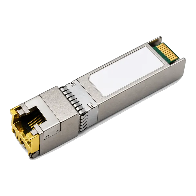
For structured aggregation racks where inter-rack distances remain within 30 to 100 metres, modular transceivers bridge optical and copper domains. Deploying the 10G SFP+ Copper RJ45 10GBASE-T 100m Cat6a/Cat7 Multi-Rate transceiver inside optical SFP+ cages allows network administrators to connect copper-based compute nodes without replacing the core optical switch. When planning mixed media topologies, review our copper SFP transceiver deployment guide to align power budgets and thermal limits across high-density line cards.
03Switching fabric capacity and packet forwarding calculations
Switching fabric capacity measures the maximum volume of raw data an ASIC can process simultaneously across all ingress and egress channels in full duplex mode. To calculate whether a 10 gigabit network switch offers a true non-blocking line-rate architecture, multiply the total port count by port line speed and double the figure for bidirectional duplex communication.
Consider an enterprise 48-port SFP+ switch with 6 uplink ports running at 40 Gbps QSFP+:
- 48 ports × 10 Gbps × 2 (full duplex) = 960 Gbps
- 6 uplink ports × 40 Gbps × 2 (full duplex) = 480 Gbps
- Total non-blocking fabric requirement = 960 Gbps + 480 Gbps = 1,440 Gbps (1.44 Tbps)
Forwarding throughput is calculated in Million Packets Per Second (Mpps) using the standard 64-byte minimum Ethernet frame size plus the 8-byte preamble and 12-byte Inter-Packet Gap (IPG), totalling 84 bytes (672 bits) per packet:
Throughput (Mpps) = (Port Speed in bps / 672 bits) × Total Port Count
For a single 10 Gbps port: 10,000,000,000 / 672 = 14.88 Mpps. Across a 48-port 10Gb platform, the ASIC forwarding rate must reach at least 714.28 Mpps to sustain wirespeed throughput under worst-case 64-byte packet storms.
04Managed versus unmanaged 10G switch operational trade-offs
A 10 gigabit managed switch provides full programmatic control over traffic prioritization, Virtual Local Area Networks (IEEE 802.1Q), link aggregation (IEEE 802.3ad LACP), and Spanning Tree protocols, whereas an unmanaged 10g switch functions strictly as a plug-and-play forwarding bridge. In core and aggregation networks, unmanaged units introduce operational risks because they lack Simple Network Management Protocol (SNMP) telemetry, Port Mirroring (SPAN), and Access Control Lists (ACLs).
However, an unmanaged switch gigabit 10gbps configuration serves isolated workgroups, high-throughput video editing suites, and dedicated lab benches where local endpoints require instant 10 Gbps throughput without configuration overhead. If your network involves multi-tenant segmentation, high-availability uplinks, or automated failover, deploying a 10gbe managed switch is essential for Layer 3 static or dynamic routing (OSPF, BGP) and IGMP snooping. For detailed architectural comparisons on unmanaged deployments, see our unmanaged Ethernet switch architecture guide.
05Power over Ethernet capabilities in 10GbE network switches
A 10gbe poe switch delivers multi-gigabit data transmission and direct DC power over a single four-pair Cat6a cable to downstream Powered Devices (PDs). Under the IEEE 802.3bt Type 4 standard (PoE++), each RJ45 port supplies up to 90W of DC power at the Power Sourcing Equipment (PSE) output, delivering 71.3W to the remote load after accounting for channel resistance over 100 metres.
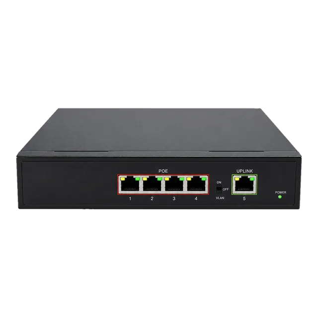
Enterprise installations increasingly require 10GBASE-T ports with PoE++ to drive Wi-Fi 6E/7 tri-band access points, pan-tilt-zoom (PTZ) IP cameras, and edge computing nodes. When engineering high-density PoE line cards, aggregate power supply sizing must prevent over-subscription. For smaller access distributions or intermediate drop-points, pairing 10Gb uplinks with lower-density distribution hardware such as the Gigabit PoE IP Ethernet Switch — 4 PoE Ports + 1 Uplink provides power delivery while offloading core fabric bandwidth.
06Port density and multi-rate configurations: 1G, 2.5G, 5G, and 10G
Multi-rate switches implement IEEE 802.3bz NBASE-T technology, allowing a single RJ45 port to auto-negotiate between 100 Mbps, 1 Gbps, 2.5 Gbps, 5 Gbps, and 10 Gbps based on cable category and channel signal-to-noise ratio. For branch offices or edge closets, a gigabit ethernet switch 10 port model often features eight 10/100/1000Base-T ports paired with two dedicated 10G SFP+ uplink ports, providing cost-effective aggregation without requiring all-10G backplanes.
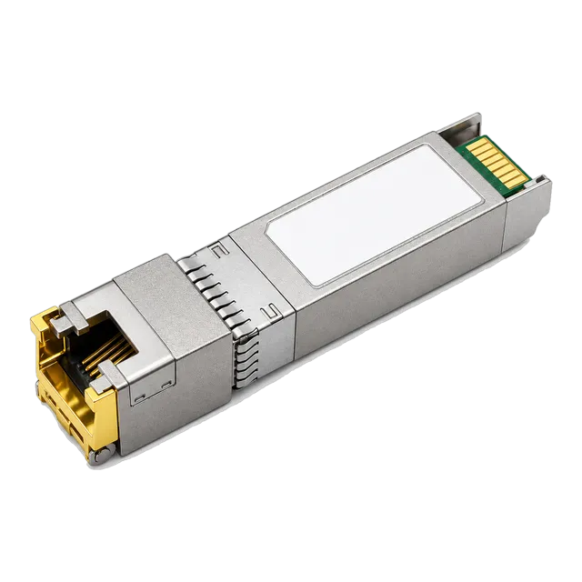
Similarly, an enterprise switch rj45 gigabit 10 ports layout can accommodate 2.5G endpoints such as network attached storage (NAS) devices and workstation NICs. Using multi-rate transceivers like the 10GBASE-T SFP+ Copper RJ45 100m Multi-Rate adapter allows modular 10gb network switch platforms to seamlessly negotiate down to 2.5G or 5G speeds over Cat5e infrastructure without forcing manual clock adjustments.
07Physical layer media selection: transceivers, DAC, and AOC
Selecting physical media for a 10gb fiber switch depends on link length, latency tolerance, cable routing radius, and thermal budgets. Within a single equipment rack or adjacent server cabinets, passive Direct Attach Copper (DAC) cables operating under SFF-8431 consume less than 0.1W per termination and exhibit near-zero transmission latency. For runs exceeding 7 metres within high-density data centres, Active Optical Cables (AOC) offer lightweight, flexible routing over multimode fiber.
The table below provides physical layer parameters across the primary interconnect options used in ten gigabit ethernet switch deployments:
| Transceiver / Media Standard | Connector Type | Media Specification | Max Reach (m) | Typical Power (W) | Standard Clause |
|---|---|---|---|---|---|
| 10GBASE-CR (DAC) | SFP+ to SFP+ | Twinaxial Copper | 7 | 0.1 | SFF-8431 |
| 10GBASE-SR | Duplex LC | OM3 / OM4 MMF | 300 / 400 | 0.8 | IEEE 802.3ae Cl. 52 |
| 10GBASE-LR | Duplex LC | G.652 SMF | 10,000 | 1.2 | IEEE 802.3ae Cl. 52 |
| 10GBASE-ER | Duplex LC | G.652 SMF | 40,000 | 1.5 | IEEE 802.3ae Cl. 52 |
| 10GBASE-T (Modular) | RJ45 | Cat6a / Cat7 UTP/STP | 30 - 100 | 2.3 - 2.8 | IEEE 802.3an |
| 10GBASE-T (Native PHY) | RJ45 | Cat6a / Cat7 UTP/STP | 100 | 3.0 - 5.0 | IEEE 802.3an |
08Thermal dissipation and power budget calculations for SFP+ optics
A high-density 10gbe switches platform loaded with 48 SFP+ ports can experience localized thermal throttling if transceiver thermal dissipation exceeds the host cage chassis cooling airflow. While standard optical transceivers (10GBASE-SR and 10GBASE-LR) consume approximately 0.8W to 1.2W, RJ45 copper transceivers draw 2.3W to 2.8W each. Populating 48 consecutive ports with copper transceivers generates over 120W of heat dissipation entirely localized at the front I/O bezel.
To calculate rack thermal cooling and switch power supply headroom, apply the thermal dissipation formula:
Total Heat (BTU/hr) = Total Electrical Load (W) × 3.412142
Worked calculation for a 48-port SFP+ switch populated with 32 optical transceivers and 16 modular copper transceivers:
- Base switch ASIC and fan load = 150W
- 32 optical transceivers × 1.0W average = 32W
- 16 copper transceivers × 2.5W average = 40W
- Total operational power consumption = 150W + 32W + 40W = 222W
- Thermal output = 222W × 3.412142 = 757.5 BTU/hr
Always verify cage vendor limits. Many switch backplanes support a maximum of 1.5W per cage on adjacent ports, necessitating a checkerboard layout when inserting high-power 10GBASE-T copper transceivers.
09Industrial environments and ruggedized 10G network switch design
Industrial applications in transport systems, utility substations, and outdoor surveillance require 10g ethernet switch designs capable of fanless operation across temperature extremes from -40°C to +85°C. Standard enterprise switches fail rapidly in harsh environments due to dust ingress, electrolytic capacitor degradation under sustained heat, and mechanical vibration. Industrial platforms feature IP30 or IP40 rated aluminium enclosures, redundant DC power inputs (12V to 48V DC), and DIN-rail or wall mounting options.
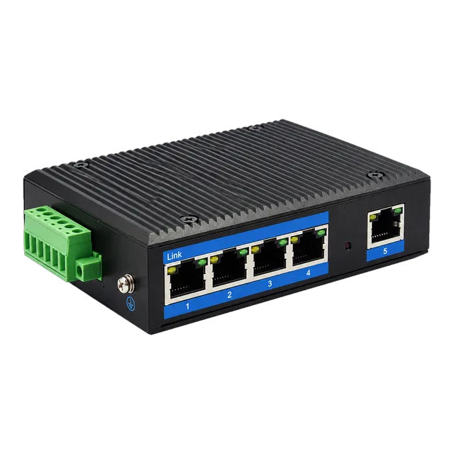
For edge aggregation points exposed to harsh external conditions, ruggedized hardware like the Outdoor Industrial Gigabit Ethernet Switch — 5× RJ45 Port handles localized harsh distribution. When linking such remote edge nodes back to a central 10 gbps switch over long distances, engineers deploy single-mode optical transceivers rated for industrial operating temperatures to guarantee consistent laser bias and sensitivity.
10Optical link monitoring with Digital Diagnostic Monitoring (DDM)
Digital Diagnostic Monitoring (DDM), standardized under SFF-8472, provides real-time telemetry from optical transceivers operating inside a 10 gig fiber switch. SFF-8472 defines an internal I2C memory map located at address A2h that reports five critical physical layer parameters: internal transceiver temperature, supply voltage, laser bias current, optical transmitter output power (Tx Power in dBm), and optical receiver input power (Rx Power in dBm).
Switch network operating systems poll these DDM registers to warn operators of impending optical link failures before uncorrectable Bit Error Rates (BER) trigger physical link drops. For example, if Rx optical power drops below the receiver sensitivity threshold (typically -14.4 dBm for 10GBASE-LR), the switch logs a syslog alert indicating fiber bending, dirty optical connectors, or excessive splice attenuation. For comprehensive steps on interpreting diagnostic registers, consult our guide to what DDM can tell you about an optical link.
11Step-by-step RFQ checklist for 10Gb Ethernet switch procurement
Drafting a rigorous Request for Quotation (RFQ) ensures that your hardware supplier delivers a 10 gbe ethernet switch matching your exact throughput, port configuration, and interoperability criteria. Use this structured engineering checklist when issuing B2B procurement specifications:
- Port Configuration and Media Form Factors: Specify the exact quantity of native 10G SFP+ cages, native 10GBASE-T RJ45 ports, multi-gigabit (2.5G/5G) ports, and 40G/100G uplink cages.
- Switch Fabric Performance: Require non-blocking wire-speed throughput (in Tbps) and minimum forwarding capacity (in Mpps) calculated at 64-byte frame size.
- Packet Buffer Architecture: State minimum shared packet buffer memory (e.g., 12MB to 32MB) to prevent micro-burst packet loss in iSCSI/Ceph storage environments.
- Layer 2 and Layer 3 Software Features: Define routing requirements (Static IPv4/IPv6, OSPFv2/v3, BGP, VRRP), VLAN capacities (4,096 VLAN IDs), and IGMPv2/v3 snooping table sizes.
- Power Supply and Cooling Redundancy: Specify dual hot-swappable AC/DC power supply units (PSUs) with N+1 or 1+1 redundancy, along with front-to-back or back-to-front airflow orientation.
- PoE Budget: If specifying PoE, designate IEEE 802.3at (30W) or IEEE 802.3bt (60W/90W) requirements and total aggregate PoE power budget in Watts.
- Transceiver EEPROM Compatibility: Mandate Multi-Source Agreement (MSA) compliance and verified host vendor microcode encoding to prevent port lockout on proprietary network operating systems.
12Frequently asked questions
What is the difference between an SFP+ switch and a 10GBASE-T switch?
An SFP+ switch uses modular optical cages accepting fiber transceivers, DACs, or copper modules with lower latency and power consumption (0.8W to 1.5W per port). A 10GBASE-T switch has fixed RJ45 ports running over Cat6a copper cabling, drawing 2.5W to 5W per port over distances up to 100 metres.
Can a 10Gb Ethernet switch port connect to a standard 1Gb network card?
Yes, most 10G SFP+ and 10GBASE-T RJ45 switch ports support backward compatibility. SFP+ cages accept standard 1.25G SFP modules, while 10GBASE-T ports utilize multi-rate auto-negotiation (IEEE 802.3bz) to clock down to 1 Gbps, 2.5 Gbps, or 5 Gbps automatically when connected to Gigabit Ethernet network interface cards.
How much power does a 10G SFP+ copper RJ45 transceiver consume?
A 10G SFP+ copper RJ45 module consumes between 2.3W and 2.8W, significantly higher than standard optical transceivers which draw under 1.0W. When populating an SFP+ switch with copper modules, verify that the switch chassis power supply and thermal airflow can support the localized heat dissipation across adjacent ports.
What cable is required for a 10Gb Ethernet switch over copper?
Category 6A (Cat6a) shielded or unshielded twisted-pair cable is required to achieve the full 100-metre reach at 10 Gbps under IEEE 802.3an. Standard Category 6 cable can support 10 Gbps speeds, but link distance is strictly limited to 37 to 55 metres depending on alien crosstalk conditions.
What is the minimum switching capacity for a non-blocking 48-port 10G switch?
A non-blocking 48-port 10Gb switch requires a switching fabric capacity of at least 960 Gbps. This is calculated as 48 ports multiplied by 10 Gbps multiplied by 2 for bidirectional full duplex communication, paired with a minimum packet forwarding throughput of 714.28 Million Packets Per Second.
Technical review note: confirm model-specific specifications with the product datasheet and the intended host documentation. Product images and application photographs are illustrative.
Discuss this with our team