Selecting an outdoor poe switch requires balancing IP enclosure ratings and passive thermal dissipation against copper link resistance losses, surge protection clamping voltages, and industrial-temperature optical uplinks back to the core aggregation tier.
01What is an outdoor poe switch and how does it function?
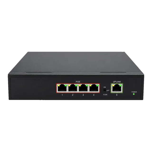
An outdoor poe switch is a hardened network bridge engineered to deliver Ethernet data connectivity and DC power over twisted-pair copper cabling to remote edge devices located outside climate-controlled facilities. Under IEEE 802.3af (PoE), IEEE 802.3at (PoE+), and IEEE 802.3bt (4PPoE), the switch injects nominal 48 V to 57 V direct current across balanced twisted pairs while maintaining standard 10/100/1000 Mbps Ethernet communication. Unlike commercial enterprise hardware limited to temperature-regulated equipment rooms, an outdoor poe switch with 4 PoE ports must maintain full frame forwarding and uninterrupted power delivery while exposed to solar radiation, seasonal sub-zero temperatures, industrial airborne contaminants, and severe electrical transient spikes.
Functionally, these platforms combine an internal industrial-grade power supply unit (PSU) or DC-DC step-up converter, an unmanaged or managed Layer 2 switching fabric, and power-sourcing equipment (PSE) controllers. The PSE actively senses connected powered devices (PD) through resistive discovery handshakes, classifies load requirements before energising conductors, and continuously monitors current draw to interrupt overcurrent conditions. To eliminate ground loops and span distances beyond the standard 100-metre copper threshold, field switches incorporate SFP ports to facilitate single-mode or multi-mode optical fibre backhaul into campus aggregation distribution points.
02Enclosure engineering: IP ratings, NEMA classifications, and venting
Enclosure protection determines whether an outdoor network switch survives sustained mechanical and environmental degradation over a multi-year service lifecycle. International Standard IEC 60529 defines Ingress Protection (IP) ratings using a two-digit matrix where the first numeral designates solid particle protection and the second denotes liquid ingress resistance. For external deployments, an IP65 rating protects completely against dust ingress and low-pressure water jets from any direction, whereas IP67 ratings mandate survival during continuous immersion down to 1 metre depth for 30 minutes. In heavy industrial and coastal applications, IP68 or IP69K specifications withstand high-pressure, high-temperature washdowns.
National Electrical Manufacturers Association (NEMA) standards provide equivalent US environmental baselines incorporating corrosion resistance and external icing performance. A NEMA 4X enclosure provides watertight protection equivalent to IP66 while adding rigorous salt-spray corrosion immunity. Field deployments relying on die-cast aluminium casings often incorporate expanded polytetrafluoroethylene (ePTFE) hydrophobic vents. These microscopic membrane vents permit bilateral air exchange to equalise internal and external atmospheric pressure differentials driven by diurnal solar cycling, preventing mechanical vacuum failure across silicone rubber perimeter gaskets while blocking liquid water entry.
03Operating temperature grades: commercial versus industrial thresholds
The internal temperature of an unventilated sealed enclosure frequently climbs 20°C to 30°C above ambient air temperatures under direct summer solar loading. Deploying an outdoor ethernet switch poe system requires components validated across wide-temperature industrial operating grades rather than commercial specifications. Commercial silicon is rated strictly from 0°C to 40°C or 50°C, leading to immediate thermal runaway, clock jitter, and premature memory failure when mounted inside unconditioned pole cabinets. Extended commercial platforms span -20°C to 60°C, while true hardened industrial platforms support a standard operating envelope of -40°C to 85°C.
Solid-state reliability adheres to the Arrhenius model, which dictates that component failure rates roughly double for every 10°C rise in junction operating temperature. In outdoor enclosures without forced-air convective cooling, heat dissipation relies strictly on conductive transfer through thermal gap pads to external aluminium heatsink fins. Engineers specifying switches must confirm that both the power supply subsystem and switching silicon sustain maximum load outputs across the full -40°C to 85°C range without de-rating the available PoE output wattage at elevated operational thresholds.
04PoE standards comparison: IEEE 802.3af, 802.3at, and 802.3bt
Modern outdoor installations interface edge equipment spanning small fixed IP cameras to high-draw multi-sensor pan-tilt-zoom (PTZ) domes, long-range radar sensors, and multi-band Wi-Fi 6/6E external access points. Selecting an outdoor rated poe switch requires matching PSE output power classes against downstream PD power demands across the established IEEE standards.
| Standard | Type | Pairs Used | PSE Output Voltage (V) | Max Power at PSE (W) | Min Power at PD (W) | Cable Category |
|---|---|---|---|---|---|---|
| IEEE 802.3af | Type 1 | 2-pair | 44.0 – 57.0 | 15.4 | 12.95 | Cat3 / Cat5e |
| IEEE 802.3at | Type 2 | 2-pair | 50.0 – 57.0 | 30.0 | 25.50 | Cat5e / Cat6 |
| IEEE 802.3bt | Type 3 | 4-pair | 50.0 – 57.0 | 60.0 | 51.00 | Cat5e / Cat6a |
| IEEE 802.3bt | Type 4 | 4-pair | 52.0 – 57.0 | 90.0 | 71.30 | Cat6 / Cat6a |
Type 1 and Type 2 systems energise two twisted pairs using either Alternative A (delivering power simultaneously over active data pairs 1-2 and 3-6) or Alternative B (delivering power over spare pairs 4-5 and 7-8). Type 3 and Type 4 architectures utilise all four twisted pairs to divide current draw, significantly lowering copper loop resistance losses and reducing heat dissipation inside high-density cable conduits.
05Calculating outdoor PoE power budgets and voltage drops
Calculating total power requirements requires factoring in cable conductor resistance, operating temperatures, and maximum instantaneous hardware draw rather than relying on nominal PD ratings. Standard solid copper 24 AWG Category 5e cabling exhibits a direct current loop resistance of approximately 18.8 Ω per 100 metres at 20°C. When ambient run temperatures rise to 50°C inside outdoor PVC or metal conduit runs, copper resistance increases by approximately 0.393% per °C according to standard temperature coefficient formulas, reaching approximately 21.0 Ω per 100 metres.
Consider an outdoor PTZ camera requiring 25.5 W at the device terminal over a 90-metre Cat5e cable link operating under Type 2 (802.3at) 2-pair power injection. At a PSE output voltage of 50.0 V DC, current through the two conductor pairs (equivalent resistance of two parallel conductors out and back: R_loop = 21.0 × 0.9 = 18.9 Ω) is governed by I = P / V. Solving the quadratic power delivery relationship reveals a loop current of approximately 0.58 A:
Cable power loss is derived from P_loss = I² × R_loop = (0.58 A)² × 18.9 Ω = 6.36 W. Consequently, the minimum continuous power drawn from the outdoor switch port is 25.5 W + 6.36 W = 31.86 W, which exceeds the standard 30.0 W PSE output threshold of an 802.3at port at nominal minimum voltage. To deploy this link reliably without undervoltage port shutdowns, the engineer must either increase PSE bus voltage to 54 V DC or specify an 802.3bt Type 3 PSE using 4-pair delivery to cut total conductor loop resistance in half.
06Surge protection, lightning suppression, and bonding topologies
Every copper cable entering or exiting an outdoor network switch functions as an antenna for electromagnetic coupling induced by indirect lightning strikes, electrostatic discharges (ESD), and industrial switching transients. International Standard IEC 61000-4-5 defines surge immunity test procedures, mandating differential-mode (line-to-line) and common-mode (line-to-ground) verification up to specified kilovolt (kV) levels. A fully hardened outdoor rated network switch incorporates primary stage gas discharge tubes (GDTs) alongside secondary fast-clamping transient voltage suppressor (TVS) diodes directly on all RJ45 differential pairs.
For rigorous field survivability, follow this step-by-step bonding and earthing sequence:
- Establish a low-impedance earth ground path yielding less than 5 Ω resistance using dedicated copper-clad ground rods bonded to the mounting pole base.
- Mechanically bond the chassis grounding lug of the outdoor ethernet switch directly to the local ground bar using minimum 6 AWG (16 mm²) stranded green/yellow copper conductor.
- Install external surge protection devices (SPDs) rated for 10 kV/10 kA at cable entry bulkheads, positioning protectors within 500 mm of the enclosure boundary.
- Terminate all exterior horizontal runs with shielded twisted pair (STP/FTP) cabling, grounding the metal shield drain wire at a single reference point to prevent circulating ground currents.
07Mounting configurations: pole, wall, and external cabinet deployment
Physical mounting hardware must withstand continuous aerodynamic wind loads, vibration, and thermal expansion across seasonal cycles. Outdoor network switches feature integrated chassis brackets or heavy-gauge 316 marine-grade stainless steel mounting kits for direct attachment to cylindrical utility poles or flat masonry walls. Direct pole mounting requires heavy-duty worm-drive band clamps rated for high tensile loads, securing the switch against wind-induced oscillations that introduce mechanical fatigue into physical cable glands.
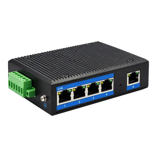
When deploying unsealed industrial DIN-rail hardware, engineers utilise an external NEMA 4X or IP66 secondary enclosure. The internal DIN rail must provide mechanical clearance of at least 75 mm above and below the switch chassis to allow natural convective airflow. For standalone unmanaged distributions where primary enclosure integration is preferred, an outdoor industrial gigabit ethernet switch with 5 RJ45 ports mounted via integrated DIN or wall ears provides direct deployment flexibility within compact weather-heads and street furniture cabinets.
08Optical uplinks and SFP modules for long-distance edge isolation
Copper twisted-pair cables operating at gigabit data rates are strictly bounded by IEEE 802.3ab to a maximum channel link length of 100 metres, inclusive of patch cords. Furthermore, long copper inter-building runs introduce dangerous ground potential differentials that induce current across cable shields and destroy switch PHY silicon. Transitioning the uplink from copper to optical fibre completely breaks galvanic paths, isolating the outdoor PoE switch from campus earth potential rises while extending backhaul link reaches from hundreds of metres up to 120 kilometres.
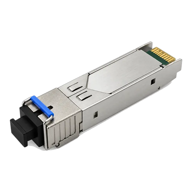
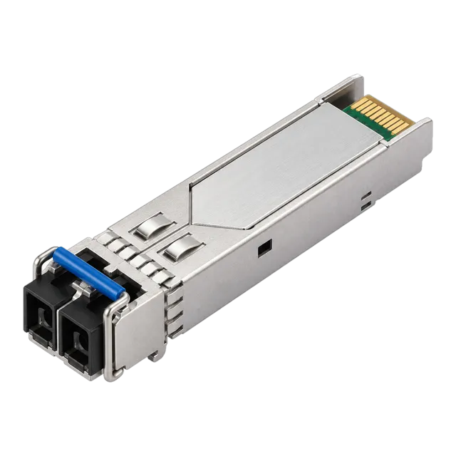
Outdoor switches equipped with SFP cages require industrial-temperature optical modules rated for operation between -40°C and 85°C. For bi-directional runs over single-strand fibre, field engineers deploy 1.25G SFP BiDi 20km optical transceivers utilising wavelength-division multiplexing (WDM) to transmit and receive across 1310 nm and 1550 nm windows simultaneously. Standard dual-strand single-mode installations routinely deploy an industrial 1.25G SFP 1310nm 20km module to achieve clean, noise-immune distribution into core aggregation rings.
09Power supply design: DC inputs, AC mains, and solar battery systems
Power supply selection dictates the reliability and continuous PoE delivery capacity of an outdoor switch installation. Outdoor locations rarely offer clean 230 V AC utility mains, frequently requiring switches that accept wide-range direct current (DC) inputs spanning 12 V, 24 V, or 48 V. Systems running on solar-charged battery banks operate nominally at 12 V or 24 V lead-acid or lithium iron phosphate (LiFePO4) bus levels. Because IEEE 802.3at requires minimum 50 V DC injection at the PSE port, switches deployed in these topologies must incorporate an integrated DC-DC boost converter capable of stepping up fluctuating 10 V–36 V battery rails to stable 54 V DC PoE rails.
Redundant dual-power inputs are essential for critical security and transportation infrastructure. Dual DC terminals allow simultaneous interconnection to a primary industrial mains rectifier and a secondary secondary DC battery backup circuit with zero switchover latency during utility dropouts. Integrated reverse-polarity protection and overvoltage crowbar clamping circuits safeguard the internal switching fabric against improper field terminations by mobile installation teams.
10Managed versus unmanaged outdoor switches for field surveillance
Selecting between managed and unmanaged switches for outdoor deployments balances hardware commissioning complexity against operational maintenance costs. Unmanaged switches offer simple plug-and-play operation, immediately bridging traffic and applying fixed power budgets without software configuration. However, deploying unmanaged platforms in remote, hard-to-access outdoor locations creates severe diagnostic blind spots: field technicians cannot inspect remote link states, check optical receiver levels, or cycle power on frozen cameras without dispatching service vehicles.
Managed outdoor PoE platforms support essential Layer 2 protocols that eliminate physical maintenance dispatches. Key managed capabilities include:
- Remote PoE port power cycling: Forcing hard cold-reboots on locked IP cameras or remote access points directly via SNMP or web interface.
- PoE scheduling and watchdog monitoring: Automatically pinging connected PD addresses and cycling port power when ICMP responses cease.
- Ring resiliency protocols: ITU-T G.8032 Ethernet Ring Protection Switching (ERPS) delivering sub-50 ms network convergence during single-link fibre cut events.
- 802.1Q VLAN segmentation: Isolating high-bandwidth outdoor video surveillance multicast streams from administrative control networks.
- Digital Diagnostic Monitoring (DDM): Real-time monitoring of SFP laser temperature, supply voltage, transmit optical power, and receive optical power via SFF-8472 registers.
11Cabling, glands, and physical termination best practice
Physical layer failures in exterior networks stem overwhelmingly from improper cable jacket stripping, defective gland assembly, and liquid ingress through conduit piping. Exterior Category cabling must feature a high-density polyethylene (HDPE) outer jacket rated for direct UV exposure and cold bend resistance down to -40°C. Standard PVC indoor jackets degrade rapidly under ultraviolet solar radiation, becoming brittle, cracking, and permitting water migration through the inner twisted pairs.
All horizontal cable entries through the enclosure chassis must use IP68-rated compression cable glands or pre-assembled IP67 industrial bayonet RJ45 couplers. Gland grommets must match the exact outer diameter (OD) of the installed cable; using an undersized cable inside an oversized gland prevents the elastomeric seal from compressing fully around the jacket circumference. Conduits must always enter the enclosure from the bottom rather than the top or sides, creating a physical drip loop that prevents rainwater running down conduit exteriors from collecting against sealing gaskets.
12Outdoor PoE switch engineering selection checklist
Engineers preparing technical tender specifications and procurement bills of materials (BOM) can evaluate candidate outdoor PoE switches against this engineering selection checklist:
| Evaluation Parameter | Target Requirement | Tender Verification Status |
|---|---|---|
| Ingress Protection | IEC 60529 IP66/IP67 or NEMA 4X certified | Verified against factory test reports |
| Operating Temperature | -40°C to +75°C (+85°C storage) continuous full-load | Thermal testing without fan assistance |
| PoE Standard Support | IEEE 802.3af/at/bt with per-port budget negotiation | Port power allocation table validated |
| Total PoE Power Budget | Calculated sum of maximum PD draw plus cable loss | PSU rated for 125% calculated total load |
| Surge Immunity | IEC 61000-4-5: Common Mode ≥6 kV, Diff Mode ≥4 kV | Integrated GDT and TVS protection array |
| Uplink Capabilities | Dual industrial 1000BASE-X or 10G SFP+ optical slots | MSA-compliant SFF-8472 DDM accessible |
| Power Input Range | Redundant dual inputs (12–57 V DC or 100–240 V AC) | Galvanic input-to-chassis isolation verified |
| Chassis Construction | Corrosion-resistant die-cast aluminium housing | Salt-spray tested per ASTM B117 |
13Commissioning, loop testing, and optical turn-up
Once the outdoor poe switch is mechanically anchored and bonded, commissioning follows a strict procedural sequence to prevent downstream equipment damage. First, measure open-circuit DC bus voltages at the switch input terminals to verify correct voltage polarity and confirm power stability before energising the system. Second, connect a portable optical power meter to incoming fibre strands to verify that optical receive levels fall comfortably within the receiver sensitivity envelope documented in our optical link budget calculation guide.
Third, plug the industrial optical transceivers into switch uplink cages and inspect link state indicators. Access the switch command-line interface or management console to verify operational optical power readings using internal DDM parameters, as detailed in our guide to what DDM can tell you about an optical link. Finally, terminate downstream copper patch cables into the PoE RJ45 ports sequentially. Monitor active power draw via the management interface as each camera or wireless access point executes its initial boot sequence, confirming that total aggregate power draw remains well within the switch continuous power supply reserve.
14Frequently asked questions
Can you put a normal PoE switch outside in an enclosure?
A standard commercial PoE switch placed in an outdoor enclosure will likely fail prematurely due to high internal heat build-up and extreme temperature fluctuations. Commercial units lack -40°C to 85°C rated silicon, conformal coating against condensation, and high-voltage surge suppression across RJ45 ports.
What is the difference between IP65, IP66, and IP67 switches?
IP65 switches resist low-pressure water jets and dust. IP66 switches withstand high-pressure water jets and heavy seas. IP67 switches remain entirely watertight even when submerged in 1 metre of water for 30 minutes, providing maximum ingress protection for severe exterior flooding environments.
How far can an outdoor PoE switch transmit power and data?
Over copper twisted-pair cabling, standard data transmission and PoE delivery reach a maximum of 100 metres per IEEE 802.3 standards. Beyond 100 metres, switches must use optical SFP uplinks to span up to 120 km, or specialised long-reach PoE extenders operating at reduced bandwidth.
Do outdoor PoE switches require dedicated surge protectors?
Yes, deploying external surge protection devices rated for at least 10 kV/10 kA at cable entry points is critical. Even switches with internal surge suppression require primary external surge protectors and a low-impedance earth ground to divert direct lightning-induced transients away from electronic components.
What cable is required for outdoor PoE switch deployments?
Deploy shielded Category 6 or 6a cabling featuring an outdoor UV-resistant high-density polyethylene jacket and internal water-blocking tape or gel. Ground the cable shield drain wire to the switch chassis ground to dissipate electrostatically coupled transient energy and preserve high-frequency data integrity.
Technical review note: confirm model-specific specifications with the product datasheet and the intended host documentation. Product images and application photographs are illustrative.
Discuss this with our team