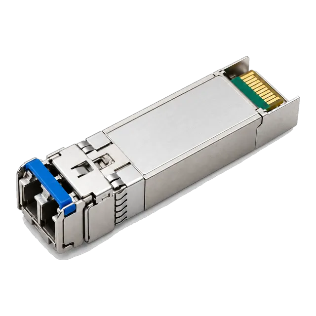
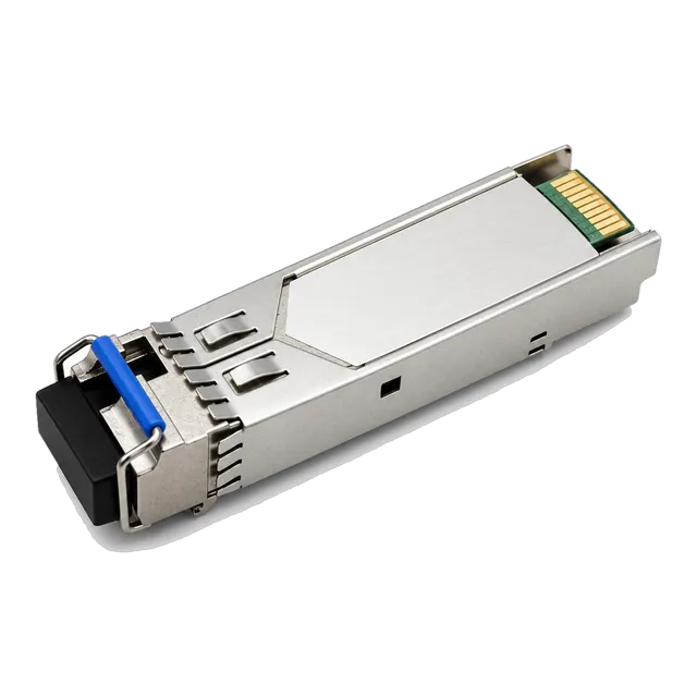
The LC fiber connector delivers low insertion loss and high packing density via its 1.25 mm ceramic ferrule, making precise end-face inspection and correct polish matching vital for reliable optical transceiver uplinks.
01What is an LC fiber connector and how does it work?
An lc fiber connector is a small-form-factor optical interface that terminates optical fibers using a 1.25 mm ceramic ferrule and an RJ-45-style latching mechanism. Developed by a major telecommunications vendor and often referred to historically as a local connector, it standardised miniaturised optical cabling across enterprise and telecommunication networks. Standardised under IEC 61754-20 and TIA-604-10 (FOCIS 10), the LC interface replaced larger legacy connectors like SC and ST by halving the required panel space while maintaining equivalent optical performance. The connector aligns two microscopic glass cores within a split ceramic sleeve inside an optical transceiver receptacle or patch adapter, permitting bidirectional light transmission with minimal attenuation.
In enterprise networking, the lc connector fiber optic format serves as the default interface for modular transceivers from 155 Mbps up to 100 Gbps. The mechanical latch ensures positive retention under mechanical vibration, preventing accidental disengagement when technicians route patch leads inside high-density distribution frames. Whether deployed on single-mode infrastructure or multimode optical links, this interface ensures stable core-to-core physical contact across operating temperatures from -40°C to +85°C.
02Mechanical design: ferrule dimensions, latching, and duplex clips
The mechanical core of an LC connector relies on a precision zirconia ceramic ferrule measuring exactly 1.25 mm in outer diameter, which is half the 2.5 mm diameter used in legacy SC connectors. This compact size allows optical transceivers such as SFP, SFP+, and SFP28 to support dual-fibre duplex links within a standard 13.4 mm module width. The ferrule bore diameter is engineered with sub-micron tolerances, typically 125.5 µm for single-mode glass and 127 µm for multimode glass, preventing lateral core offset during mating.
LC assemblies are manufactured in both simplex and duplex form factors. Simplex connectors terminate a single strand of lc optical fiber, frequently deployed in bidirectional WDM links where transmission and reception occur over one strand. Duplex assemblies combine two simplex bodies using a rigid or removable plastic clip with a standard pitch of 6.25 mm. This spacing aligns directly with the optical transmit (Tx) and receive (Rx) bores on MSA-compliant transceivers. Technicians can detach the duplex clip on site to invert Tx and Rx lines when resolving cross-over polarities during commissioning.
03LC UPC vs LC APC: polish types and return loss characteristics
The primary functional difference between LC UPC and LC APC connectors is the geometry of the ferrule end-face polish, which directly determines optical return loss. An LC UPC (Ultra Physical Contact) connector features a slightly domed end-face polished at a 90-degree angle relative to the fiber core, yielding an optical return loss (ORL) of ≥ 50 dB. In contrast, an LC APC (Angled Physical Contact) connector incorporates an 8-degree mechanical angle across the ferrule surface, directing back-reflected light into the fiber cladding to achieve an ORL of ≥ 65 dB.
Connector housing colours adhere to strict conventions defined by TIA-568.3-D to prevent mismatched matings. UPC single-mode connectors use blue housings, multimode UPC connectors use aqua (OM3 or OM4) or lime green (OM5), and APC connectors strictly use green housings. Mating an LC/UPC connector to an LC/APC port creates an air gap that damages the delicate ceramic ferrule end-faces and introduces optical insertion losses exceeding 4.0 dB. Most digital Ethernet transceivers—including standard 10GBASE-LR and 25GBASE-LR modules—require blue LC UPC terminations, whereas telecommunications PON, analog RF video, and certain long-reach DWDM networks require green LC APC interfaces to suppress transmitter feedback noise.
04Matching lc single mode fiber and multimode cables to transceivers
Selecting the correct cable assembly requires matching the optical core diameter of the patch cord to the internal optical sub-assembly of the host transceiver. An lc single mode fiber patch lead uses a 9 µm core diameter conforming to ITU-T G.652.D or bend-insensitive G.657.A1 specifications, designed for 1310 nm, 1490 nm, and 1550 nm laser sources. Multimode LC patch leads utilize a 50 µm graded-index core optimised for 850 nm and 910 nm VCSEL (Vertical-Cavity Surface-Emitting Laser) sources over distances up to 400 metres.
Deploying a multimode cable on a single-mode transceiver introduces extreme modal dispersion and catastrophic coupling loss, rendering links inoperable. Conversely, coupling a single-mode patch cord into a multimode transceiver creates severe core underfill, inducing differential mode delay (DMD). For short-reach data centre racks, engineers specify OM4 multimode fiber optic lc cable assemblies. For building backbones, campus runs, or telco metro links exceeding 500 metres, 9/125 µm single-mode LC cables are mandatory. For a detailed review of single-mode cable standards and patch considerations, see our single mode fiber LC connector engineering guide.
05LC fiber connector standards and optical loss specifications
Optical attenuation across an lc fiber connector interface is governed by IEC 61753-1 and TIA-568.3-D industry standards. The maximum allowable insertion loss for a field-tested mated pair under TIA-568.3-D is 0.75 dB, although factory-polished premium assemblies typically achieve random-mate insertion losses between 0.10 dB and 0.25 dB. Keeping attenuation low across patch connections ensures sufficient optical power reaches the receiver optical sub-assembly (ROSA).
IEC 61753-1 categorises random-mated connector performance into defined attenuation grades based on testing against a master reference lead. The table below outlines these standardised attenuation and return loss grades for single-mode and multimode LC interfaces:
| Standard Grade | Mean Insertion Loss (dB) | Max Insertion Loss (97% of connections, dB) | Return Loss UPC (dB) | Return Loss APC (dB) |
|---|---|---|---|---|
| Grade A (SMF Reference) | ≤ 0.07 | ≤ 0.15 | ≥ 55 | ≥ 70 |
| Grade B (Standard High-Spec SMF) | ≤ 0.12 | ≤ 0.25 | ≥ 50 | ≥ 65 |
| Grade C (Standard Commercial SMF) | ≤ 0.25 | ≤ 0.50 | ≥ 50 | ≥ 65 |
| Grade D (Commercial MMF) | ≤ 0.35 | ≤ 0.75 | ≥ 30 | N/A |
Grade B components are recommended for optical spans running near transceiver link margins, ensuring that intermediate patch panels do not deplete optical budgets before signal reaches the terminal detector.
06Worked calculation: optical link budget with lc fiber connection points
Calculating the optical loss budget ensures that cumulative channel attenuation across an lc fiber connection path does not exceed the dynamic range between the transmitter optical sub-assembly (TOSA) and the ROSA. The link budget calculation aggregates fiber cable attenuation, mated connector pair losses, splice losses, and an operational safety margin. The general formula is: Channel Loss = (Fiber Attenuation Rate × Distance) + (Connector Pairs × Loss per Pair) + (Splices × Loss per Splice) + Safety Margin.
Consider an enterprise campus link deploying a pair of 25G SFP28 LR 1310nm 10km transceivers over a 6.5 km single-mode run traversing two intermediate cross-connect patch panels:
- Transceiver Minimum Launch Power (Tx Min): -7.0 dBm
- Transceiver Receiver Sensitivity (Rx Max): -10.3 dBm (per IEEE 802.3cc 25GBASE-LR)
- Total Available Power Budget: -7.0 dBm - (-10.3 dBm) = 3.3 dB
- Fiber Loss at 1310 nm: 6.5 km × 0.35 dB/km = 2.275 dB
- LC Connector Loss (4 mated pairs total: 2 at transceivers + 2 at patch bays @ 0.20 dB/pair): 4 × 0.20 dB = 0.80 dB
- Fusion Splice Loss (2 splices @ 0.05 dB/splice): 2 × 0.05 dB = 0.10 dB
- Total Calculated Link Loss: 2.275 dB + 0.80 dB + 0.10 dB = 3.175 dB
- Operating Margin: 3.3 dB - 3.175 dB = 0.125 dB
Because the resulting margin of 0.125 dB is lower than the recommended 2.0 dB engineering margin for transmitter aging and temperature drift, this link requires Grade B low-loss LC terminations (0.10 dB/pair) or upgrading the optics to a 20 km or 40 km optic. Engineers can test custom budgets quickly using our optical link budget calculator.
07LC uniboot and high-density cable architectures for lc networking
LC uniboot patch cords consolidate two individual fiber strands into a single round 2.0 mm or 3.0 mm cable jacket terminated into a single dual-ferrule housing, halving physical cable volume in dense raceways. In high-density lc networking environments such as spine-leaf data centre switches and SAN directors, conventional duplex zip-cord cabling obstructs airflow and clutters vertical management channels. The uniboot design eliminates individual zip-cord splits, reducing tray congestion by up to 50%.
A critical operational feature of high-grade LC uniboot assemblies is tool-less polarity reversal. In standard duplex LC cords, swapping the transmit and receive strands requires opening a rigid plastic clip with a pick or razor, risking fiber strain or micro-bends. Modern uniboot assemblies allow technicians to rotate the connector outer housing or release an integrated latch mechanism to switch A-B polarity to A-A polarity in seconds without tools. For architectural guidelines on deploying high-density uniboot cabling, consult our dedicated LC uniboot connector guide.
08Cleaning and inspection procedures for an lc optical connector
Cleaning an lc optical connector ferrule is mandatory before every mating cycle because a single microscopic dust particle of 1 to 5 µm can completely occlude a 9 µm single-mode core. Dust debris pressed between mating ferrules generates core pitting, permanently degrading return loss and causing signal back-reflection into the laser cavity. Technicians must follow the IEC 61300-3-35 international inspection standard using the following five-step process:
- Inspect the ferrule end-face using a calibrated 200x or 400x optical fiberscope, checking Zone A (the core) and Zone B (the cladding) for particulates, oil films, or scratches.
- If debris is detected, execute dry cleaning using a dedicated 1.25 mm mechanical push-action cleaning tool, applying the tip straight against the ferrule and advancing the micro-woven fabric tape.
- Re-inspect the ferrule to verify that all core and cladding contamination has been eliminated according to the pass/fail criteria of IEC 61300-3-35.
- If stubborn oil or residue remains, perform wet-to-dry cleaning using a lint-free optical wipe moistened with high-purity optical solvent (> 99.8% isopropyl alcohol or optical-grade hydrofluoroether), followed immediately by a dry wipe pass.
- Inspect the transceiver internal optical bore using a dedicated 1.25 mm bulkhead inspection probe before final insertion. Never blow compressed air into an optical transceiver port.
09Transceiver interface compatibility: SFP, SFP+, SFP28, and QSFP ports
Optical transceiver form factors rely heavily on the LC interface across 1 Gbps, 10 Gbps, 25 Gbps, and select 40G/100G architectures. Pluggable modules conforming to the SFF Committee specifications—including SFP (SFF-8472), SFP+ (SFF-8431), and SFP28 (SFF-8402)—standardise on duplex LC optical receptacles. This common physical interface ensures backward physical patch compatibility when upgrading network aggregation uplinks from 1 Gbps to 10 Gbps or 25 Gbps without replacing existing patch cords.
Transceivers fall into two primary LC connection formats:
- Duplex LC Transceivers: Feature separate Tx and Rx optical barrels side by side, used in dual-fiber optics like 10GBASE-LR, 25GBASE-SR, and 100GBASE-CWDM4 QSFP28 modules that multiplex internal wavelengths onto duplex LC ports.
- Simplex LC BiDi Transceivers: Feature a single 1.25 mm LC receptacle integrating a diplexer or WDM filter to transmit and receive on different wavelengths over one strand of glass, such as our 1.25G BiDi Single-Fiber SFP transceiver.
For higher speeds such as 40GBASE-SR4 or 100GBASE-SR4, transceivers shift to MPO multi-fiber push-on connectors. However, single-mode long-reach variants like 40GBASE-LR4 and 100GBASE-LR4 retain the duplex LC interface by multiplexing four internal optical lanes across a single duplex pair via an integrated optical mux/demux.
10Comparison: LC vs SC, MPO, and CS optical connectors
Selecting between an lc fibre connector and alternative optical connector profiles depends on port density requirements, insertion loss budgets, and transceiver form factors. While legacy installations historically utilised SC connectors for robust manual handling, modern high-density networking relies on the LC format or ultra-dense connectors like CS and SN in next-generation 400G systems. The table below compares optical connector formats commonly encountered across switching and routing environments:
| Connector Type | Ferrule Diameter / Type | Standard Insertion Loss (dB) | Duplex 1U Patch Panel Density | Primary Transceiver Compatibility | Best Application Use Case |
|---|---|---|---|---|---|
| LC (Local Connector) | 1.25 mm Zirconia | 0.15 – 0.25 | Up to 144 Fibres (72 Duplex) | SFP, SFP+, SFP28, QSFP-LR4 | Enterprise LAN, Data Centre Racks, Telco SAN |
| SC (Subscriber Connector) | 2.50 mm Zirconia | 0.20 – 0.30 | Up to 72 Fibres (36 Duplex) | GBIC, Legacy SFP, 1G Media Converters | Industrial automation, GPON ONT drop terminals |
| MPO | Multi-fiber polymer (12/24f) | 0.35 – 0.70 | Up to 288+ Fibres | QSFP+, QSFP28 parallel optics | Parallel optics, multi-fiber trunk backbone routing |
| CS Connector | Dual 1.25 mm Zirconia | 0.15 – 0.25 | Up to 288 Fibres (144 Duplex) | QSFP-DD, OSFP (2x100G Breakout) | High-density 200G/400G spine-leaf architectures |
While MPO dominates short-reach parallel optics and CS expands ultra-dense 400G optics, the LC connector remains the industry workhorse for 1G through 100G point-to-point single-mode and multimode duplex links.
11Procurement checklist: specifying fiber cable lc connector assemblies for RFQs
Procuring fiber cable lc connector assemblies for mission-critical enterprise or carrier networks requires clear technical specifications to prevent receiving sub-standard patch cables. Omitting mechanical or polish tolerances in request-for-quotation (RFQ) documentation often results in high-loss cables with excessive return reflections that destabilise sensitive transceivers. Use the following technical checklist when preparing optical patch cord procurement specifications:
- Optical Fiber Standard: Specify exact glass geometry—Single-mode OS2 (ITU-T G.652.D or G.657.A1 bend-insensitive) or Multimode OM4 or OM5 (ISO/IEC 11801).
- End-Face Polish: Mandate UPC (Physical Contact, blue) for standard Ethernet optics, or APC (8-degree angled, green) for WDM/telecom distribution lines.
- Insertion and Return Loss Limits: State maximum IL ≤ 0.25 dB (Grade B) and ORL ≥ 50 dB (UPC) or ≥ 65 dB (APC) per IEC 61753-1 testing.
- Cable Construction: Designate standard duplex zip-cord (2.0 mm / 3.0 mm) or high-density uniboot with tool-less polarity switch mechanisms.
- Jacket Material: Specify Low Smoke Zero Halogen (LSZH) for European/UK installations or OFNP (Plenum) for North American plenum spaces.
- Quality Documentation: Require 100% factory interferometry test reports verifying end-face curvature radius (7–25 mm), fiber undercut/protrusion (< 50 nm), and apex offset (< 50 µm).
12Verifying lc fiber connectivity and optical health using DDM
Verifying link continuity across an lc fiber connection is best performed by accessing Digital Diagnostic Monitoring (DDM / DOM) telemetry directly from the host transceiver operating system. Standardised under SFF-8472, DDM provides real-time telemetry including optical Transmit Power (Tx), optical Receive Power (Rx), operating temperature, supply voltage, and laser bias current. By querying the transceiver via switch command-line interfaces (CLI), network administrators can inspect optical signal degradation without inserting physical optical power meters into active production paths.
When an LC connector end-face accumulates debris or is poorly seated within the optical receptacle, the switch CLI reports an immediate drop in optical Rx power while the remote partner Tx power remains stable. A discrepancy exceeding 1.5 dB between the remote transmitter launch power and the expected calculated attenuation points directly to dirty connector ferrules, a micro-bend along the patch cord, or a misaligned duplex clip. Regular monitoring of DDM levels establishes a baseline across all ports in your network, alerting operations teams to gradual contamination before packet loss occurs. For complete guidance on diagnosing telemetry parameters, consult our engineering guide on understanding DDM optical diagnostics.
13Frequently asked questions
What is the difference between an LC and SC fiber connector?
An LC connector uses a small 1.25 mm ceramic ferrule and an RJ-45-style latch, whereas an SC connector uses a 2.5 mm ferrule with a push-pull latch. LC connectors offer double the port density of SC connectors, making them the standard interface for modern SFP, SFP+, and SFP28 optical transceivers.
Can you plug an LC UPC connector into an LC APC port?
No, an LC UPC connector must never be plugged into an LC APC port. The flat UPC ferrule collides with the 8-degree angled APC ferrule, creating an air gap that causes high insertion loss exceeding 4 dB, extreme back-reflection, and permanent physical scratches on both optical end-faces.
What is an LC uniboot connector?
An LC uniboot connector integrates two fibers into a single round 2.0 mm or 3.0 mm cable jacket terminated into a single duplex housing. This configuration cuts cable bulk by up to 50% in dense network racks and typically includes a mechanism for reversing polarity without specialised tools.
Why does an LC connector use a 1.25 mm ferrule?
The 1.25 mm ceramic ferrule was engineered to reduce optical connector dimensions by half compared to 2.5 mm legacy connectors. This miniaturisation matches the physical dimensions of standard modular transceivers like SFP and SFP28, enabling high-density switch front panels with up to 48 duplex ports per rack unit.
How much insertion loss is normal for an LC connector?
Under TIA-568.3-D standards, the maximum acceptable insertion loss for a field-mated LC connector pair is 0.75 dB. However, factory-polished high-performance Grade B LC assemblies typically deliver insertion losses between 0.10 dB and 0.25 dB per mated pair when kept clean and properly aligned.
Technical review note: confirm model-specific specifications with the product datasheet and the intended host documentation. Product images and application photographs are illustrative.
Discuss this with our team