Selecting the correct fiber optic ethernet cable requires matching core glass geometry and transceiver wavelength to a validated link loss budget, ensuring clean connector end-faces and jacket compliance for fire and tensile safety.
01What is a fiber optic ethernet cable assembly?
A fiber optic ethernet cable is a dedicated physical transmission assembly comprising one or more optical glass fibres, protective cladding, strength members, and precision factory-terminated connectors designed to carry Ethernet frames as light pulses across local, campus, and metropolitan networks. Unlike copper Category cables that transmit electrical voltages subject to capacitive drop and electromagnetic interference (EMI), an optical ethernet cable transmits modulated photons within infrared windows—primarily 850 nm, 1310 nm, and 1550 nm—defined by IEEE 802.3 standards. In an enterprise or data centre environment, a fiber ethernet cable interconnects top-of-rack switches, storage area networks (SAN), and core routing platforms via pluggable optical transceivers. Within structured cabling, engineers designate this medium as a fiber lan cable or optical fibre lan cable, providing the physical backbone linking telecommunications rooms to main distribution frames. The core assembly contains a central silica glass core surrounded by a lower-refractive-index cladding (typically 125 μm diameter), buffered by acrylate coating and reinforced with aramid yarn inside an overall protective sheath.
02Single-mode versus multimode fiber network cable types
Single-mode optical fiber network cable carries light along a single transverse spatial mode through a narrow core of 8 to 9 μm, whereas multimode fiber uses a wider core of 50 μm or 62.5 μm that permits multiple light rays to propagate simultaneously. Standardised under ISO/IEC 11801 and ITU-T recommendations, these optical fiber lan cable classes address fundamentally different distance and bandwidth parameters. Multimode cabling—categorised as OM1, OM2, OM3, OM4, and OM5—relies on vertical-cavity surface-emitting lasers (VCSELs) operating at 850 nm or 953 nm. While cost-effective for short data centre runs under 150 m at 100 Gb/s, multimode performance is fundamentally bounded by modal dispersion, where different light modes arrive at the detector at slightly offset times, causing intersymbol interference. In contrast, single-mode fiber (OS1 and OS2), standard under ITU-T G.652.D and bend-insensitive ITU-T G.657.A1/A2, eliminates modal dispersion entirely. Chromatic dispersion remains the only physical glass constraint, allowing a single-mode fiber network cable to achieve reach from 500 m to 100 km at bit rates from 1.25 Gb/s to 400 Gb/s. When planning physical plant runs exceeding 300 m, single-mode infrastructure represents the standard design choice for future-proof optical ethernet.
03Optical connector form factors: LC, SC, and MPO terminations
Optical connector terminations align the microscopic glass cores with mechanical tolerances sub-micron in scale to keep insertion loss below 0.35 dB per mated pair. The Lucent Connector (LC) is the universal standard for modern high-density networking, utilising a 1.25 mm ceramic ferrule in duplex snap-in housings that interface directly with SFP, SFP+, and SFP28 transceivers. Subscriber Connector (SC) interfaces utilise a 2.5 mm push-pull ferrule, widely deployed on legacy patch panels, passive optical network (PON) customer premises equipment, and standalone media converters. For high-density aggregation architectures running 40G, 100G, or 400G, Multi-fiber Push-On (MPO/MTP) connectors house 8, 12, 16, or 24 fibres in a single rectangular ferrule, interfacing directly with parallel optics like 100GBASE-SR4 transceivers. Connector polishing also defines performance: Ultra Physical Contact (UPC), marked in blue, provides return loss ≤ -50 dB for standard data centre optical ethernet; Angled Physical Contact (APC), polished at an 8-degree angle and marked in green, achieves return loss ≤ -65 dB, mandatory for RF video, optical time-domain reflectometry (OTDR) testing, and single-strand BiDi telecommunications lines.
04Ethernet cable for fiber internet vs true optical fiber drop
An ethernet cable for fiber internet typically refers to a four-pair copper twisted-pair patch cord (such as Cat6 or Cat6a) that carries copper Gigabit signals from an Optical Network Terminal (ONT) to a consumer or enterprise router, whereas a true fiber internet wire is the dielectric glass drop cable entering the premises from the street. When service providers install internet cable fiber optic connections, the external infrastructure delivers an ITU-T G.657.A2 single-mode drop cable straight to an optical wall outlet or optical modem. The physical link from this wall plate to the ONT is an indoor fiber optic modem cable—often a 2.0 mm simplex yellow OS2 patch lead terminated with green SC/APC connectors. Many consumers colloquially confuse this with a fiber internet cord or fiber wifi wire, but the physical handoff changes completely at the ONT: the ONT performs optical-to-electrical modulation, presenting an 8P8C (RJ45) jack. If your router features a native SFP or SFP+ port, you can bypass the separate ONT box by inserting a compatible optical transceiver directly into the router, transforming the link into an end-to-end optical ethernet feed.
05Transceiver pairing: matching optical ethernet cable to SFP, SFP+, and QSFP optics
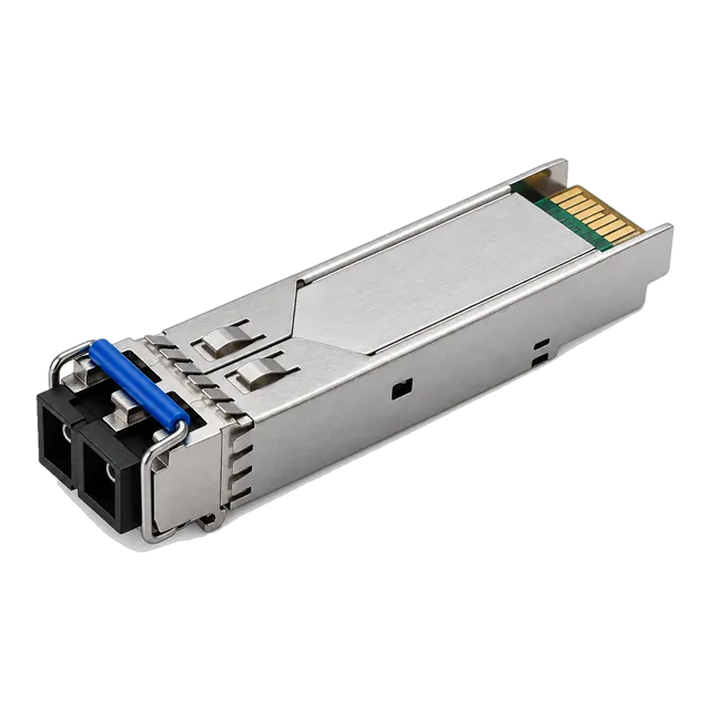
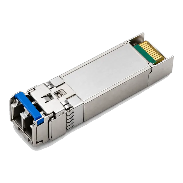
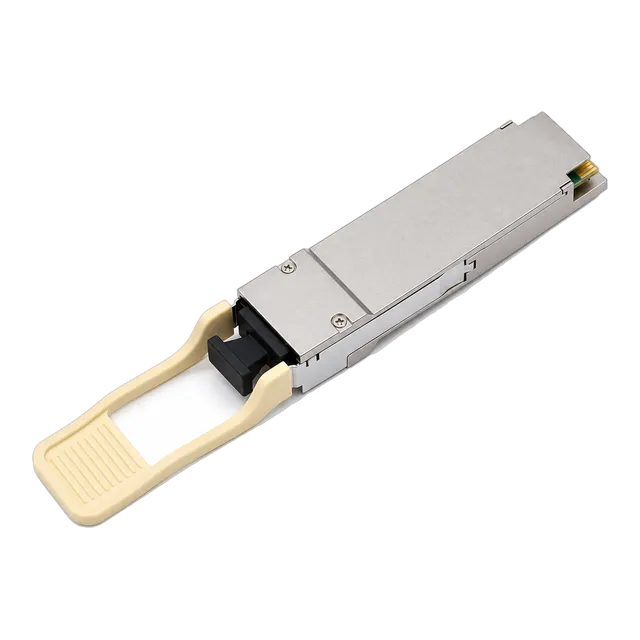
A fiber optic ethernet cable cannot transmit data without matching transceivers that align optical wavelength, transmit power, and modal bandwidth with the physical fiber core. Connecting a single-mode 1310 nm transceiver to an OM4 50/125 μm multimode patch cord causes severe differential mode delay (DMD) and excessive insertion loss, resulting in bit error rate (BER) spikes or complete link failure. Conversely, firing an 850 nm VCSEL into an OS2 9/125 μm single-mode cable introduces massive coupling loss because the optical spot size dramatically exceeds the tiny 9 μm core. For standard Gigabit deployments, an optical patch cord links switches via transceivers such as the 1.25G SFP 1310nm SMF Dual-Fiber Transceiver over duplex OS2 fiber. In enterprise backbone upgrades running 25 Gb/s, engineers deploy the 25G SFP28 LR 1310nm Single-Mode Transceiver over OS2 LC duplex assemblies up to 10 km. For top-of-rack server clusters inside dense equipment rooms, short multimode MPO trunks pair seamlessly with the 100G QSFP28-SR4 850nm MPO-12 Transceiver across OM4 cable up to 100 m.
06Optical link budget calculation for enterprise fiber LAN networks
An optical link budget calculation determines whether the total optical power emitted by the transmitter is sufficient to reach the receiver after accounting for all attenuation sources across the fiber optic lan network. If the attenuation exceeds the available power margin, the optical receiver cannot decode incoming frames, leading to packet drops. To calculate the available budget, subtract the receiver sensitivity from the minimum optical launch power specified in the transceiver datasheet: Power Budget (dB) = P_Tx_min (dBm) - P_Rx_sens (dBm). Next, calculate total channel insertion loss: Total Loss (dB) = (Cable Length × Attenuation Rate) + (Mated Connector Pairs × Connector Loss) + (Splices × Splice Loss) + Safety Margin. To avoid field degradation, always build in a 3.0 dB safety margin for component aging and future field repairs, as detailed in our guide to optical link budget calculation.
Consider a practical enterprise campus backbone link running 10GBASE-LR across 8.5 km of OS2 single-mode optical ethernet cable operating at 1310 nm:
- Transmitter Minimum Launch Power (P_Tx_min): -8.2 dBm
- Receiver Sensitivity (P_Rx_sens): -14.4 dBm
- Calculated Power Budget: -8.2 dBm - (-14.4 dBm) = 6.2 dB
- Fiber Attenuation (8.5 km × 0.35 dB/km at 1310 nm): 2.975 dB
- Mated Connector Loss (4 duplex LC pairs × 0.30 dB/pair): 1.20 dB
- Fusion Splice Loss (4 splices × 0.05 dB/splice): 0.20 dB
- Engineering Safety Margin: 1.50 dB
- Total Channel Insertion Loss: 2.975 + 1.20 + 0.20 + 1.50 = 5.875 dB
Because the total calculated loss of 5.88 dB is less than the 6.20 dB power budget, the link margin is positive (+0.32 dB), confirming the physical channel will achieve error-free transmission.
07Fiber optic ethernet cable specification comparison
Selecting the appropriate fiber network cable standard requires comparing modal bandwidth, glass geometry, physical reach limits, and laser transmission windows. The table below outlines international transmission standards governing structured premises cabling in accordance with ISO/IEC 11801, TIA-568-C.3, and IEEE 802.3 specifications.
| Fiber Class | Core / Cladding Diameter (μm) | Light Source & Wavelength (nm) | Overfilled Launch / EMB (MHz·km) | Max Reach @ 10G (m) | Max Reach @ 25G (m) | Max Reach @ 100G (m) | Nominal Attenuation (dB/km) |
|---|---|---|---|---|---|---|---|
| OM1 | 62.5 / 125 | LED @ 850 | 200 | 33 m | Not Supported | Not Supported | 3.5 @ 850 nm |
| OM2 | 50 / 125 | LED @ 850 | 500 | 82 m | Not Supported | Not Supported | 3.0 @ 850 nm |
| OM3 | 50 / 125 | VCSEL @ 850 | 2000 | 300 m | 70 m | 70 m (SR4) | 3.0 @ 850 nm |
| OM4 | 50 / 125 | VCSEL @ 850 | 4700 | 400 m | 100 m | 100 m (SR4) | 2.8 @ 850 nm |
| OM5 | 50 / 125 | SWDM @ 850-953 | 4700 (850 nm) / 2470 (953 nm) | 400 m | 100 m | 100 m (BiDi / SWDM4) | 2.8 @ 850 nm |
| OS1 | 9 / 125 | Fabry-Pérot / DFB @ 1310/1550 | Single Mode (Dispersive) | 10,000 m | 10,000 m | 10,000 m (LR4) | 1.0 @ 1310 nm |
| OS2 | 9 / 125 | DFB / EML @ 1310/1550 | Single Mode (Low Water Peak) | 40,000 m | 40,000 m | 40,000 m (ER4) | 0.35 @ 1310 nm / 0.22 @ 1550 nm |
08Integrating legacy twisted-pair copper with optical fibre lan cable runs
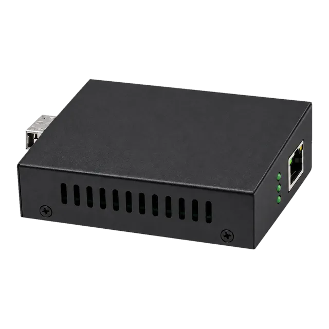
Network switches without native SFP ports require media conversion or modular transceivers to bridge copper RJ45 interfaces with optical fibre lan cable infrastructure. Twisted-pair copper cabling, such as Cat6, carries a strict 100-metre operational channel limit under IEEE 802.3an standards. When enterprise backbone links or remote access points exceed this physical threshold, engineers convert the electrical signal into an optical ethernet stream. For multi-gigabit copper aggregation, deploying a dedicated 2.5G Fiber to Ethernet Media Converter enables smooth bridging between 2.5GBASE-T access points and long-distance single-mode SFP uplinks without replacing the underlying edge switch. For applications where direct transceiver replacement is viable, modular 10GBASE-T transceivers can convert SFP+ slots directly into copper interfaces, though power consumption and heat dissipation must be evaluated, as discussed in our analysis of copper vs fiber at the access layer. Utilizing modular media conversion protects capital investment while extending local area network segments across kilometres of optical glass.
09Jacket ratings and environmental requirements: LSZH, OFNP, and armoured cables
The chemical composition of a fiber optic cable jacket dictates its flame resistance, smoke toxicity, and physical crush tolerance under building code standards. In European installations, Low Smoke Zero Halogen (LSZH) jackets complying with IEC 60332-1 and IEC 61034 are standard practice; they emit minimal smoke and zero acidic halogen gases when exposed to open flame, protecting personnel and sensitive electronic hardware. In North American jurisdictions governed by NFPA 70 (National Electrical Code), optical cables require Optical Fiber Nonconductive Plenum (OFNP) ratings for installation within drop ceilings, raised floors, and HVAC air-handling spaces. Riser spaces between building floors require OFNR (Optical Fiber Nonconductive Riser) sheaths. For harsh campus pathways, duct transitions, or industrial plants exposed to rodents and physical crushing, interlocking aluminium armour or steel tape armour (corrugated steel tape) prevents mechanical puncture while maintaining bend radii. Enterprise engineers should select bend-insensitive fiber compliant with ITU-T G.657.A2, which allows minimum bend radii down to 7.5 mm without inducing microbending or macrobending attenuation penalties.
10Troubleshooting optical ethernet cable loss, contamination, and polarity
Over 80% of optical ethernet physical-layer link failures stem from microscopic connector end-face contamination rather than severed glass or defective electronics. Dust particles as small as 1 μm settling on a 9 μm single-mode LC ferrule core can cause severe back-reflection, optical scatter, and permanent pitting if mated under high mechanical compression. Systematic troubleshooting follows a standardized, four-step verification sequence:
- End-face visual inspection: Inspect every connector ferrule using an optical video microscope conforming to IEC 61300-3-35 criteria before cleaning and mating; clean using dry lint-free wipes or click-style cleaning pens.
- Polarity verification: Confirm transmit-to-receive (Tx-to-Rx) cross-connection. Dual-fiber optical ethernet links require Type A-to-B crossover polarity under TIA-568 standards; if both transceivers fire into each other's transmitters, the link state remains down. Invert the LC duplex clip if reverse polarity is detected.
- Visual continuity tracing: Connect a 650 nm red Visual Fault Locator (VFL) to identify physical fiber breaks, macrobends, or crossed patch panel leads.
- Digital Diagnostic Monitoring (DDM): Query host switch CLI registers via SFF-8472 to verify received optical power (Rx Power) in dBm. If Rx power sits below the transceiver's operational sensitivity threshold, perform OTDR trace testing to identify localized splice anomalies or high-loss mated connections.
11Procurement checklist for optical ethernet infrastructure RFQs
An ambiguous Request for Quotation (RFQ) leads to mismatched ferrule polishes, incorrect jacket flammability, and optical transceivers incompatible with installed fiber network cable drops. When ordering bulk trunks, structured patch cords, and optical transceivers from an optical connectivity hardware manufacturer, procurement teams should complete the following structured technical parameters:
| Procurement Parameter | Engineering Requirement | Common Values / Specification Details |
|---|---|---|
| Fiber Mode & Geometry | Glass core / cladding standard | Single-Mode OS2 (9/125 μm) or Multimode OM4 (50/125 μm) |
| ITU-T / ISO Standard | Bend sensitivity and water peak | ITU-T G.652.D (Standard) or ITU-T G.657.A2 (Bend-Insensitive) |
| Connector Types | A-end and B-end mechanical style | Duplex LC, Simplex SC, or MPO-12 (Base-8 / Base-12) |
| Polish Type | End-face contact geometry | UPC (Blue ferrule, data) or APC (Green ferrule, PON/WDM) |
| Channel Length | End-to-end physical span | Expressed in metres (patch) or kilometres (outside plant) |
| Jacket Flammability | Local building code rating | LSZH (IEC 60332-1) or OFNP Plenum (NFPA 262) |
| Polarity Configuration | Duplex or multi-fiber orientation | TIA-568 Type A-to-B (Duplex) or Method B (MPO trunk) |
| Target Optics Form Factor | Transceiver interface specification | SFP+ (10G), SFP28 (25G), or QSFP28 (100G) |
| Insertion Loss Budget | Maximum allowable loss per cord | ≤ 0.20 dB (Low Loss) to ≤ 0.35 dB (Standard) |
12How to specify fiber optic ethernet cable for your next network build
Designing and purchasing an enterprise optical ethernet infrastructure requires balancing immediate port bandwidth against long-term optical distribution frame (ODF) lifecycle demands. Begin by mapping out the physical routing topology and determining whether link lengths dictate single-mode OS2 or multimode OM4 cabling. For data centre interconnects and campus runs exceeding 150 m, standardise exclusively on single-mode OS2 to eliminate bandwidth upgrade bottlenecks when migrating from 10G to 25G, 100G, and beyond. Calculate your link loss budgets using conservative component insertion losses and a 3.0 dB safety margin, then verify your assumptions using our interactive optical link budget calculator. If you require technical validation for host coding compatibility, custom cable breakout harnesses, or industrial-temperature transceiver optics, contact the engineering team at MARS via our technical inquiry portal or email inquiry@optical-module-factory.com for sample evaluations and comprehensive BOM reviews.
13Frequently asked questions
Can I plug a fiber optic ethernet cable directly into my computer?
No, standard computer motherboards lack native optical ports. You must install a dedicated PCIe optical Network Interface Card (NIC) with an SFP+ or SFP28 cage, or connect your computer via a standard copper RJ45 patch cord to an Ethernet switch or media converter linked to the optical network.
What is the difference between OS2 and OM4 fiber cables?
OS2 is single-mode fiber with a tiny 9 μm core designed for 1310 nm and 1550 nm laser signals over distances up to 40 km. OM4 is multimode fiber with a 50 μm core using 850 nm VCSEL lasers, limited to 400 m at 10 Gb/s and 100 m at 100 Gb/s.
Is an ethernet cable for fiber internet the same as a fiber patch cord?
No. An ethernet cable for fiber internet is usually a copper Cat6 or Cat6a cable with RJ45 plugs running from the optical network terminal (ONT) to your router. A fiber patch cord is a flexible glass cable transmitting light directly between optical ports.
Why are single-mode optical ethernet cables yellow and multimode cables aqua?
TIA-598 colour-coding standards visually identify optical glass types to prevent field misconnections. Standard single-mode OS2 jackets are yellow, multimode OM3 is aqua, OM4 is typically Erika violet or aqua, OM5 is lime green, and legacy OM1 is orange.
Does bending a fiber optic network cable break the glass or drop the signal?
Sharp bends cause macrobending attenuation, leaking light out of the core and dropping the signal. While standard G.652.D fiber degrades under tight bends, modern G.657 bend-insensitive fiber allows tight bend radii down to 7.5 mm without cracking the glass or inducing significant packet loss.
Can I connect single-mode and multimode fiber using a coupler?
Directly coupling single-mode to multimode fiber causes significant optical mismatch. Launching light from a 50 μm multimode core into a 9 μm single-mode core induces severe attenuation exceeding 15 dB, while single-mode into multimode causes differential mode delay; an active media converter or transceiver bridge is required.
Technical review note: confirm model-specific specifications with the product datasheet and the intended host documentation. Product images and application photographs are illustrative.
Discuss this with our team