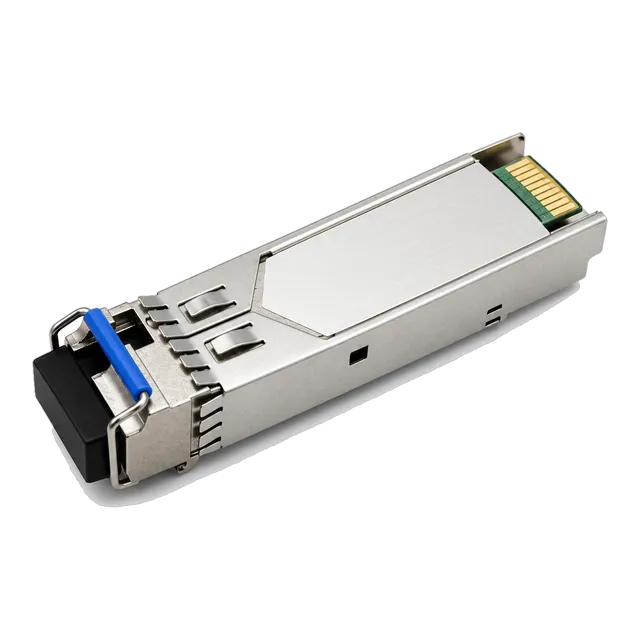
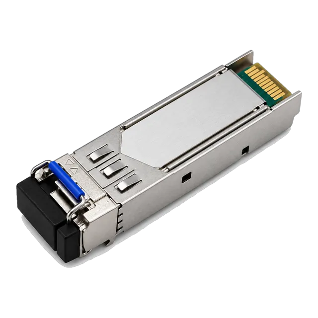
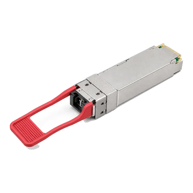
A bidirectional transceiver doubles optical strand capacity by combining transmit and receive paths onto a single optical fibre using integrated wavelength division multiplexing diplexers, requiring complementary upstream and downstream wavelength pairing and rigorous link budget validation.
01What is a bidi transceiver and how single-fibre transmission works
A bidi transceiver is an optical module that transmits and receives optical signals over a single strand of fibre by using two distinct wavelengths. Standard dual-fibre transceivers allocate one fibre core for transmitting (Tx) and an adjacent strand for receiving (Rx). In contrast, a bidi transceiver combines both directional channels onto one optical interface using internal wavelength division multiplexing (WDM) micro-optics. This architecture halves the physical cabling requirements across outside plant runs, campus backbones, and data centre interconnects.
Deploying a single-strand link requires complementary end points. Because simultaneous transmission on identical wavelengths down a single fibre induces catastrophic backscatter interference, one terminal transmits at wavelength A and receives at wavelength B, whilst the remote terminal transmits at wavelength B and receives at wavelength A. In technical procurement and engineering documentation, these matched units are designated as upstream (often called U-type or Type A) and downstream (D-type or Type B) modules. Without this complementary arrangement, bi-directional communication fails.
02Bidi transceiver internal architecture: WDM diplexers and optical isolation
The internal assembly of a bidirectional optical module relies on an integrated optical sub-assembly known as a bi-directional optical sub-assembly (BOSA) containing a micro-optic WDM filter. Traditional transceivers house a separate transmitter optical sub-assembly (TOSA) and receiver optical sub-assembly (ROSA) aligned to distinct ports of a duplex LC or SC receptacle. In a bidi design, the BOSA integrates a laser diode, a photodiode detector, and a 45-degree thin-film filter (TFF) inside a single hermetic package coupled to a simplex optical connector.
The thin-film filter serves as an optical diplexer that separates outgoing and incoming light paths based on wavelength. The internal laser emits outgoing light through the filter directly into the single optical fibre. Incoming light from the remote terminal hits the same filter at an angle designed to reflect the incoming wavelength directly into the receiver photodiode. Crosstalk suppression requires high optical isolation, typically exceeding 30 dB, preventing local laser emissions from blinding the local receiver photodiode. Modern transceivers also integrate an optical isolator at the transmitter output to block reflected counter-propagating signals from destabilising the laser cavity, preserving laser linewidth and low relative intensity noise (RIN).
03Standard wavelength pairings across single-mode bidi optics
Single-mode bidi optics operate using standardised wavelength pairs chosen to avoid the high water-peak attenuation zone and minimise chromatic dispersion. For gigabit Ethernet access links under IEEE 802.3ah (1000BASE-BX10), the industry-standard pairing is 1310 nm for the upstream transmitter and 1490 nm for the downstream transmitter. For long-reach industrial routes extending beyond 20 km, engineers frequently select 1310 nm / 1550 nm or 1490 nm / 1550 nm pairs, taking advantage of the lower optical attenuation coefficient (typically 0.22 dB/km) in the 1550 nm C-band.
Higher-speed links operating at 10 Gb/s and 25 Gb/s under IEEE 802.3ae and IEEE 802.3cp shift to tighter channel allocations. The predominant 10GBASE-BX and 25GBASE-BR pairing utilises 1270 nm and 1330 nm. This 60 nm channel spacing allows robust filter design inside standard small form-factor pluggable (SFP) packages while keeping both wavelengths close to the zero-dispersion wavelength of ITU-T G.652 single-mode fibre. Detailed wavelength specifications and optical channel bands can be cross-referenced in our guide to bidirectional SFP wavelength pairs.
04Multimode bidi optical transceiver designs for 40G and 100G short-reach links
Multimode bidi transceivers provide high-bandwidth migration over existing OM3 and OM4 duplex LC cabling inside enterprise data centres. Standard short-reach multi-lane implementations, such as 40GBASE-SR4 or 100GBASE-SR4, mandate twelve-fibre MPO/MTP parallel cabling, where four fibres transmit and four receive. A multimode bidi optical module eliminates the need to replace duplex patch fields by multiplexing two counter-propagating channels over each strand of a standard duplex LC assembly.
In a 40G bidi implementation, the transceiver incorporates two 20 Gb/s VCSEL channels operating at nominal centre wavelengths of 850 nm and 900 nm. Each strand simultaneously transmits 20 Gb/s in one direction while receiving 20 Gb/s in the reverse direction, delivering an aggregate bidirectional throughput of 40 Gb/s over two OM4 fibres up to 150 metres. For 100G bidi variants, PAM4 modulation enables dual 50 Gb/s optical lanes operating at 850 nm and 910 nm. This approach enables network architects to upgrade core switch-to-switch interconnects from 10G to 40G or 100G without ripping out existing duplex LC structured cabling runs.
05Bidi fiber deployment economics: halving dark fibre leasing and infrastructure costs
Deploying bidi fiber architectures reduces ongoing operating expenses by doubling the capacity of existing physical conduit and leased dark fibre routes. When metropolitan carriers or enterprise networks lease dark fibre on a per-strand monthly tariff, running dual-fibre duplex optics requires two billable strands per transmission link. Transitioning that circuit to a bidi optical transceiver immediately frees up the second strand for another dedicated service or halves the recurring recurring strand lease charges.
Inside greenfield telecommunications builds, such as fibre-to-the-home (FTTH) access networks or 5G mobile fronthaul, single-strand optical routing cuts passive patch panel requirements, splice cassette counts, and outdoor closure footprint by 50%. A project engineer deploying a 48-port aggregation switch can support 48 distinct subscribers using a 48-fibre optical distribution frame (ODF) instead of requiring a 96-fibre panel. This reduction in passive infrastructure hardware, combined with streamlined outside plant cable management, offsets the marginal hardware cost difference between duplex and simplex transceiver packages.
06Optical link budget calculation for single-strand bidi links
Calculating the optical link budget for a single-strand bidirectional circuit requires evaluating both directional paths independently because fibre attenuation varies significantly across different optical wavelengths. Single-mode silica fibre specified under ITU-T G.652.D exhibits higher attenuation at 1310 nm (roughly 0.35 dB/km) than at 1550 nm (roughly 0.22 dB/km). Consequently, the upstream link path operating at 1310 nm experiences higher insertion loss over distance than the complementary downstream path running at 1550 nm.
Consider a 20 km single-strand link using a 1.25G BiDi single-fiber SFP transceiver 1310nm/1550nm 20km with two mated connector pairs (0.5 dB loss each) and four fusion splices (0.1 dB loss each). The worst-case path occurs at the shorter 1310 nm transmission window:
- Transmitter minimum launch power: -9.0 dBm
- Receiver sensitivity: -20.0 dBm
- Total power budget available: -9.0 dBm - (-20.0 dBm) = 11.0 dB
- Fibre cable loss (20 km × 0.35 dB/km at 1310 nm): 7.0 dB
- Connector loss (2 pairs × 0.5 dB): 1.0 dB
- Splice loss (4 splices × 0.1 dB): 0.4 dB
- Total link attenuation: 7.0 dB + 1.0 dB + 0.4 dB = 8.4 dB
- Calculated power margin: 11.0 dB - 8.4 dB = 2.6 dB
Because the 2.6 dB safety margin satisfies the standard operational margin threshold of 2.0 to 3.0 dB, the link will operate cleanly. However, if the design engineer evaluated only the 1550 nm path (20 km × 0.22 dB/km = 4.4 dB cable loss, giving a 5.2 dB margin), the installation would risk intermittent packet loss or bit errors in the reverse 1310 nm direction. For more details on calculating optical link limits, consult our guide to optical link budget calculation.
07Standards and compliance: IEEE 802.3ah, 802.3cp, and SFF-8472 digital diagnostic monitoring
Standardised bidi transceivers comply with IEEE physical layer protocols and SFF multi-source agreements (MSAs) to ensure physical dimensions, electrical signalling, and optical parameters are fully uniform across vendors. Gigabit access links adhere to IEEE 802.3ah clauses 58 and 59, defining 1000BASE-BX10 upstream and downstream optical specifications. For higher-speed point-to-point links, the IEEE 802.3cp task force standardised 10 Gb/s, 25 Gb/s, and 50 Gb/s bidirectional access links over distances of 10 km, 20 km, and 40 km, providing interoperable optical budgets for 5G wireless fronthaul architectures.
Digital diagnostic monitoring (DDM), also referred to as digital optical monitoring (DOM), is governed by the SFF-8472 specification. Through an internal I2C two-wire serial interface, host network switches read real-time operational parameters stored in memory addresses A0h and A2h. For bidi optics, continuous telemetry monitoring of internal transceiver temperature, supply voltage, laser bias current, transmitted optical power, and received optical power (Rx power) is critical. Because backscatter can skew optical measurements, DDM provides the engineering visibility required to detect laser degradation or dirty connector interfaces before link degradation causes interface flapping.
08Common form factors: comparing SFP, SFP+, SFP28, and QSFP28 bidi optical module options
A wide selection of bidi optical module variants is available across standard form factors, scaling from low-speed metro access up to 100 Gb/s aggregation switches. Choosing the correct form factor depends directly on required throughput, reach, host port density, and optical cabling type. The table below outlines concrete engineering parameters across widely deployed single-fibre and multimode bidi module families:
| Form Factor | Standard Designation | Data Rate (Gb/s) | Wavelength Pair (nm) | Fibre Type | Max Reach (km) | Optical Connector |
|---|---|---|---|---|---|---|
| SFP | 1000BASE-BX10 | 1.25 | 1310-Tx / 1490-Rx | SMF (G.652) | 10 – 20 | Simplex LC / SC |
| SFP | 1000BASE-BX40 | 1.25 | 1310-Tx / 1550-Rx | SMF (G.652) | 40 | Simplex LC |
| SFP+ | 10GBASE-BX10 | 10.31 | 1270-Tx / 1330-Rx | SMF (G.652) | 10 – 20 | Simplex LC |
| SFP+ | 10GBASE-BX80 | 10.31 | 1490-Tx / 1550-Rx | SMF (G.652) | 80 | Simplex LC |
| SFP28 | 25GBASE-BR20 | 25.78 | 1270-Tx / 1330-Rx | SMF (G.652) | 20 | Simplex LC |
| QSFP+ | 40G BiDi SR | 40.00 | 850 / 900 (Dual) | MMF (OM4) | 0.15 | Duplex LC |
| QSFP28 | 100G BiDi LR1 | 106.25 | 1271-Tx / 1331-Rx | SMF (G.652) | 10 – 20 | Simplex LC |
For mid-speed multi-gigabit campus drops, engineers can review our range of 10G SFP+ transceivers, or select modern high-density models such as the 25GBASE-BR20 SFP28 BiDi single-fiber transceiver designed specifically for 5G wireless fronthaul deployments.
09Dispersion and attenuation trade-offs across 1270/1330 nm and 1490/1550 nm bands
Selecting between the 1270/1330 nm and 1490/1550 nm optical bands requires balancing optical attenuation against chromatic dispersion penalties. Standard G.652 single-mode fibre exhibits its zero-dispersion wavelength near 1312 nm, with dispersion values below 3.5 ps/(nm·km) across the O-band (1260 to 1360 nm). In contrast, chromatic dispersion rises to approximately 17 to 18 ps/(nm·km) in the C-band (1530 to 1565 nm). For high-baud-rate signals such as 25G NRZ or 50G PAM4, severe chromatic dispersion causes significant inter-symbol interference (ISI), limiting uncompensated reach in the 1550 nm window.
Conversely, optical attenuation behaves in the opposite manner. The fibre loss profile drops from roughly 0.35 dB/km at 1310 nm down to roughly 0.20 dB/km at 1550 nm. For long-distance spans of 40 km to 80 km at data rates of 1.25 Gb/s or 10 Gb/s, link budgets are primarily attenuation-limited rather than dispersion-limited. Therefore, 80 km optical modules leverage the 1490/1550 nm or 1510/1570 nm wavelength pairing equipped with electro-absorption modulated lasers (EML) or narrow-linewidth distributed feedback (DFB) lasers to bridge the distance without exceeding dispersion tolerance limits.
10Diagnosing reflection and Rayleigh backscatter in single-strand networks
Because both transmission directions share the same physical glass core in a single-fibre link, optical return loss (ORL) and Rayleigh backscatter present serious engineering failure points. In a standard dual-fibre link, reflections from dirty connector end-faces simply bounce back down the dedicated transmit strand toward the laser isolator, leaving the separate receive strand completely unaffected. In a single-strand system, light reflected from an intermediate patch panel or mechanical defect travels backward along the single fibre core directly toward the local receiver diplexer.
If the reflected transmit light matches the receiver's optical acceptance band, or if the internal thin-film filter exhibits poor out-of-band rejection, the reflected signal swamps the sensitive photodiode. This optical interference degrades the signal-to-noise ratio, causing packet discards and uncorrectable bit errors. To mitigate optical reflections in single-strand networks:
- Inspect and clean every optical connector using an automated scope before mating.
- Enforce angled physical contact (APC) polishing on SC connectors where specified, as APC end-faces achieve optical return loss exceeding 60 dB, compared to 45 to 50 dB for standard UPC polishes.
- Ensure that total link return loss remains within MSA tolerances, generally exceeding 26 dB for short-reach optics and 30 dB for long-haul networks.
- Use an optical time-domain reflectometer (OTDR) operating at both transmission wavelengths to identify localized reflective events exceeding 0.5 dB along the route.
11Interoperability and matching complementary upstream and downstream modules
A bidi optical transceiver link will not establish carrier sync if both ends of the single fibre run the same optical model. A widespread field error occurs when commissioning engineers deploy two identical upstream transceivers (for example, two 1310-Tx / 1490-Rx units) on either side of a dark fibre run. In this scenario, both transmitters emit optical energy at 1310 nm, but neither receiver accepts 1310 nm light, resulting in a dark link and an immediate loss-of-signal (LOS) alarm on the switch ports.
To guarantee complete optical interoperability across single-fibre links:
- Confirm that the transmitter nominal centre wavelength on terminal A matches the receiver passband of terminal B within specified spectral tolerances (typically ±10 nm for DFB lasers).
- Verify that both host transceivers utilise identical modulation protocols (such as non-return-to-zero / NRZ for 10G and 25G, or 4-level pulse amplitude modulation / PAM4 for high-speed single-lambda designs).
- Ensure that receiver dynamic range is respected; deploying an 80 km long-reach bidi optic on a 3 km link without an optical attenuator will saturate or damage the local avalanche photodiode (APD) receiver.
- Review our practical field checklist in BiDi modules: confirm the pair before ordering to establish foolproof operational procedures for field crews.
12RFQ checklist and procurement specification for bidi optics
When preparing a request for quotation (RFQ) or engineering bill of materials for bidirectional optical transceivers, network procurement teams must specify exact optical, physical, and host compatibility requirements to avoid delivery mismatches. Providing generic descriptions such as '10G bidi module' frequently results in mismatched wavelength allocations, incorrect temperature ratings, or EEPROM coding incompatibilities with the host switch operating system.
Copy and complete the following engineering specification checklist for each bidirectional circuit line item:
- Form Factor & Target Speed: (e.g., SFP+ 10.3125 Gb/s, SFP28 25.78125 Gb/s, QSFP28 106.25 Gb/s)
- Pairing Balance: Specify matched pairs (e.g., 50x Upstream 1270-Tx / 1330-Rx and 50x Downstream 1330-Tx / 1270-Rx)
- Optical Reach & Power Budget: Target distance (e.g., 10 km, 20 km, 40 km) with minimum guaranteed power budget (dB)
- Optical Connector Interface: Simplex LC (standard) or Simplex SC (legacy/FTTH); state UPC or APC polish
- Operating Temperature Grade: Commercial (0°C to 70°C) or Industrial (-40°C to +85°C for outdoor hardened enclosures)
- Host Platform Coding: Exact target switch, router, or server platform model numbers and operating system versions
- Diagnostics: SFF-8472 / SFF-8636 compliant digital diagnostic monitoring enabled
For high-capacity aggregation upgrades requiring single-fibre 100 Gb/s links, specify high-performance options such as the 100G BiDi QSFP28 LR1/ER1 single-fiber optical transceiver to double data rates over long spans without deploying additional multiplexing shelves.
13Frequently asked questions
What is the difference between a BiDi transceiver and a standard duplex transceiver?
A BiDi transceiver transmits and receives over a single optical fibre strand using two distinct wavelengths separated by an internal WDM diplexer filter. A standard duplex transceiver requires two fibre strands: one dedicated to transmitting and the other dedicated to receiving on the same nominal wavelength.
Do BiDi transceivers always need to be deployed in matched pairs?
Yes, BiDi transceivers must always be installed in complementary pairs. One module operates as the upstream unit (transmitting on wavelength A, receiving on wavelength B), while the remote module operates as the downstream unit (transmitting on wavelength B, receiving on wavelength A). Two identical units cannot communicate.
Can I connect a BiDi transceiver to a standard duplex transceiver?
No, a single-fibre BiDi transceiver cannot establish a link with a standard duplex transceiver. BiDi modules require complementary optical wavelength pairs multiplexed onto one strand, whereas duplex transceivers use separate transmit and receive strands running on identical wavelengths without internal optical diplexing.
What is the difference between 1270/1330 nm and 1310/1490 nm BiDi optics?
The 1310/1490 nm pairing is standard for 1 Gb/s access and GPON networks, whereas 1270/1330 nm is the standard allocation for 10 Gb/s and 25 Gb/s links. The 1270/1330 nm band provides lower chromatic dispersion penalties near the zero-dispersion window of standard G.652 single-mode fibre.
Why do BiDi transceivers commonly use simplex LC connectors?
Because all bidirectional transmission and reception occurs across a single glass fibre core, only one optical interface is required. The simplex LC connector provides a compact, secure latching mechanism that fits neatly into standard SFP, SFP+, and SFP28 mechanical port dimensions.
Does a BiDi transceiver introduce higher latency than a duplex optical link?
No, a BiDi transceiver does not introduce measurable transmission latency compared to duplex optics. The micro-optic thin-film diplexer filters separate optical wavelengths passively at the speed of light, introducing zero electronic packet queuing, buffering, or serialization latency to the network path.
Technical review note: confirm model-specific specifications with the product datasheet and the intended host documentation. Product images and application photographs are illustrative.
Discuss this with our team