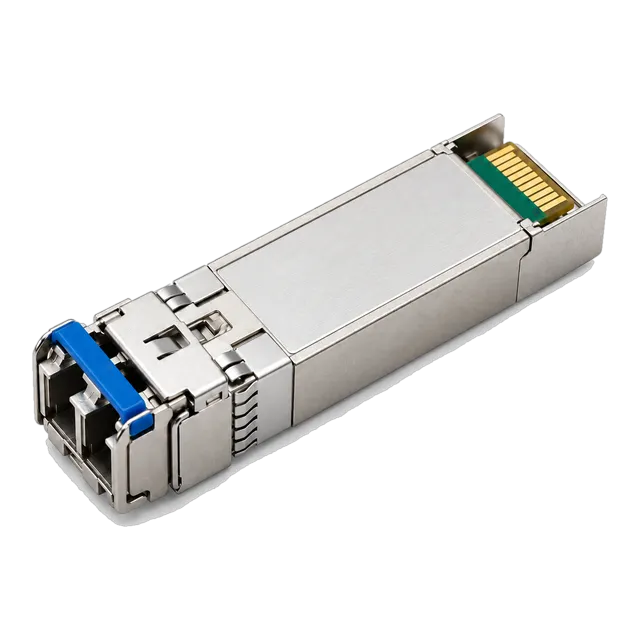
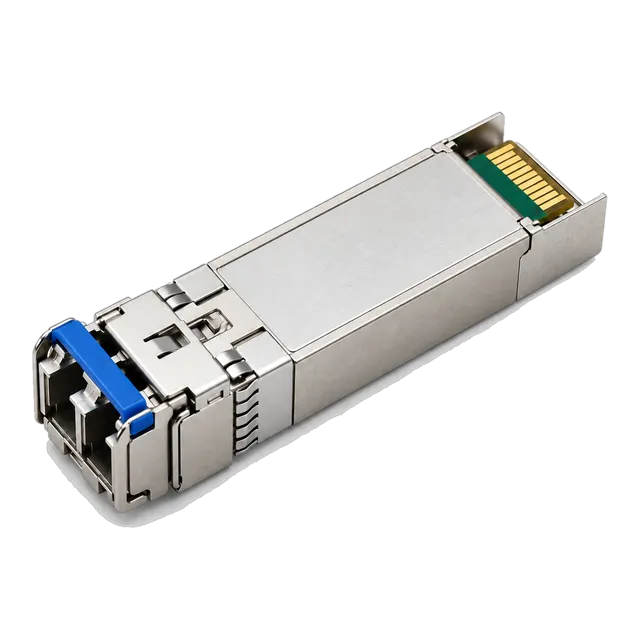
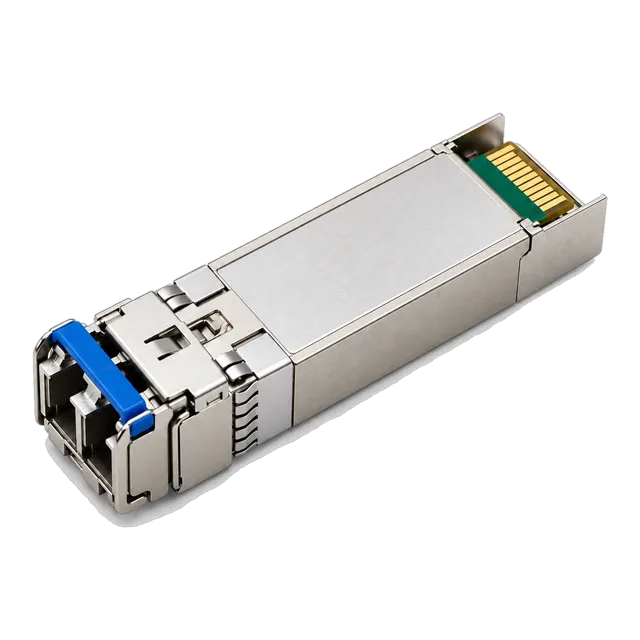
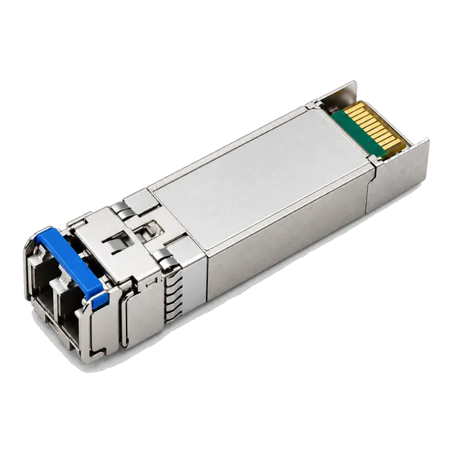
The SFP 25G SR S provides cost-optimised short-reach 25GbE connectivity over multimode fibre up to 100 metres, requiring IEEE 802.3by Clause 108 RS-FEC on the host switch to close the link budget reliably.
01Understanding the SFP 25G SR S optical architecture
The sfp 25g sr s is an enterprise-grade short-reach optical module designed for 25 Gigabit Ethernet (25GbE) connections over duplex multimode fibre (MMF). Operating at a nominal centre wavelength of 850 nm, this SFP28 transceiver uses a vertical-cavity surface-emitting laser (VCSEL) transmitter coupled with a PIN photodetector receiver. The physical interface matches the enhanced small form-factor pluggable mechanical standard defined in SFF-8432, whilst high-speed electrical signalling adheres to the 25GBASE-SR specifications established by IEEE 802.3by Clause 112.
Unlike multi-channel form factors such as QSFP28, which aggregate four 25 Gb/s electrical lanes to achieve 100 Gb/s, the 25G SFP28 module family executes transmission across a single physical lane running at 25.78125 GBd. This single-lane design significantly simplifies Top-of-Rack (ToR) switch-to-server interconnect architectures, allowing enterprise data centres to quadruple the port density of traditional 10G links without requiring re-cabling or complex multi-fibre breakouts.
The module housing incorporates an industry-standard duplex LC optical receptacle, dual-wire serial management via SFF-8472, and internal Clock and Data Recovery (CDR) circuits on both the transmit and receive paths. These integrated CDR elements lock onto the incoming 25.78125 Gb/s electrical signals from the host board, suppressing high-frequency phase jitter before driving the internal VCSEL diode.
02SFP 25G SR S optical and physical specifications
Optical parameters for the sfp 25g sr s follow strict bounds defined by IEEE 802.3by to guarantee inter-device interoperability across standards-compliant physical layers. Standard commercial units, such as the 25G SFP28 SR 850nm 100m transceiver, operate within tightly controlled transmit power envelopes and receiver sensitivities to prevent photodiode saturation over short patching runs.
| Parameter | Minimum | Typical | Maximum | Unit |
|---|---|---|---|---|
| Data Rate (per lane) | — | 25.78125 | — | Gb/s |
| Centre Wavelength (λc) | 840 | 850 | 860 | nm |
| RMS Spectral Width (Δλ) | — | — | 0.6 | nm |
| Average Launch Power | -8.4 | — | +2.4 | dBm |
| Optical Modulation Amplitude (OMA) | -6.4 | — | +3.0 | dBm |
| Receiver Sensitivity (OMA, post-FEC) | — | — | -10.3 | dBm |
| Receiver Overload (Average Power) | +2.4 | — | — | dBm |
| Receiver Damage Threshold | +3.4 | — | — | dBm |
| Extinction Ratio (ER) | 2.0 | — | — | dB |
| Power Dissipation | — | 0.8 | 1.0 | W |
The receiver sensitivity figure of -10.3 dBm OMA is specified under the explicit condition that Reed-Solomon Forward Error Correction (RS-FEC) operates across the link. When engineers configure host systems without forward error correction, the required input power rises dramatically to ensure uncorrected bit errors do not compromise network frame delivery.
03Transmission distance limits across OM3, OM4, and OM5 multimode fibre
A 25GBASE-SR SFP28 link reaches a maximum distance of 70 metres over OM3 laser-optimised multimode fibre and 100 metres over OM4 or OM5 fibre. The physical reach is constrained primarily by modal dispersion, where varying light modes travel at divergent group velocities along the 50/125 μm graded-index silica core, generating severe intersymbol interference (ISI) at 25.78125 GBd.
Standard IEC 60793-2-10 categorises multimode fibres by their minimum overfilled launch (OFL) bandwidth and effective modal bandwidth (EMB). The higher the EMB, the longer the optical pulse maintains its temporal integrity prior to detection by the receiver photodiode:
- OM3 Fibre (850 nm EMB: 2000 MHz·km): Supports link lengths up to 70 m. Ideal for legacy containment rows or intra-rack jumpers originally installed for 10GbE deployments.
- OM4 Fibre (850 nm EMB: 4700 MHz·km): Extends transmission range to 100 m. This represents the primary media standard for modern structured cabling within enterprise data halls.
- OM5 Wideband Fibre (850 nm EMB: 4700 MHz·km): Achieves the same 100 m limit as OM4. Although OM5 supports wavelength division multiplexing between 850 nm and 953 nm, a standard 25G SFP module uses only the 850 nm window, deriving no distance advantage over OM4.
- Legacy OM1 / OM2 Fibre (62.5/125 μm and 50/125 μm): Not supported under IEEE 802.3by specifications due to extreme modal dispersion, which truncates functional transmission distances to under 20 metres.
04The role of Reed-Solomon forward error correction in 25G links
Reed-Solomon Forward Error Correction (RS-FEC), codified in IEEE 802.3by Clause 108 as RS(528,514), is mathematically essential to close optical link budgets on 25GBASE-SR channels. High-speed serial transceivers operating at 25 Gb/s incur optical channel penalties that make achieving a raw pre-FEC Bit Error Rate (BER) of 10-12 economically unfeasible without driving laser costs to prohibitive levels.
Instead, IEEE 802.3by relies on a tandem scheme:
- The host physical coding sublayer (PCS) encodes outgoing Ethernet frames using an RS(528,514) algorithm, appending 14 parity symbols to every 514 data symbols.
- The physical transmission medium operates at a raw pre-FEC BER target of 10-5.
- Upon frame reception, the host silicon executes error correction on the interleaved symbols, recovering payload bits to an effective post-FEC BER of better than 10-12.
Operating RS-FEC introduces an algorithmic latency of approximately 250 nanoseconds per direction. For ultra-low-latency financial trading platforms or high-performance computing (HPC) clusters, network administrators sometimes attempt to run without FEC (Clause 112 No-FEC mode). However, operating an SFP 25G SR S transceiver with FEC disabled drops the optical link margin significantly, cutting the supported transmission distance over OM4 fibre from 100 metres to less than 30 metres, even with pristine end-face cleanliness.
05S-Class versus standard optical transceivers: operational differences
S-Class transceivers are commercial, enterprise-targeted optics that omit complex telecommunications protocols like OTN (Optical Transport Network) and WAN PHY to provide lower acquisition costs. For engineers evaluating data centre access layers, modules designated with an "-S" suffix or enterprise-tier firmware focus specifically on IEEE 802.3 Ethernet compliance across standard commercial environments.
Unlike industrial temperature modules or carrier-grade optical units, commercial enterprise transceivers like the 25GBASE-SR SFP28 850nm VCSEL module are rated strictly for operating case temperatures between 0°C and 70°C (32°F to 158°F). Carrier-grade optics, by comparison, must operate across an industrial temperature range from -40°C to +85°C to withstand unconditioned outdoor roadside cabinets or cell tower base stations.
Furthermore, S-Class optics omit legacy optical protocols such as Synchronous Optical Network (SONET), Fibre Channel over Ethernet protocol translations, or custom vendor multi-rate fallbacks. In switch-to-switch and server-to-ToR configurations that handle native Ethernet traffic, an S-Class module performs identically to higher-tier transceivers while delivering lower power dissipation and reduced unit pricing.
06Worked calculation: 25GBASE-SR optical link budget and power margin
An optical link budget calculation verifies that total channel insertion losses do not exceed available transmitter-to-receiver power margins before hardware installation. To model a practical enterprise deployment, consider an 80-metre OM4 multimode run routed across two structured patch panels between an access leaf switch and a rack compute node.
First, establish the minimum Optical Modulation Amplitude (OMA) budget using IEEE 802.3by parameters:
- Minimum Tx Launch Power (OMA): -6.4 dBm
- Receiver Sensitivity (OMA, RS-FEC enabled): -10.3 dBm
- Total Available Optical Budget: (-6.4 dBm) - (-10.3 dBm) = 3.9 dB
Next, sum the physical channel losses across the 80-metre link:
- Fibre Cable Attenuation: OM4 attenuation at 850 nm is 3.0 dB/km. For 80 metres (0.080 km): 0.080 × 3.0 dB/km = 0.24 dB
- Patch Panel Insertion Loss: Two mated pairs of LC-LC patch connections, budgeted at a conservative 0.35 dB per connection (TIA-568 standard): 2 × 0.35 dB = 0.70 dB
- Transceiver Connector Interfaces: Two equipment connections (one at each transceiver interface) at 0.20 dB: 2 × 0.20 dB = 0.40 dB
- Total Physical Insertion Loss: 0.24 dB + 0.70 dB + 0.40 dB = 1.34 dB
Finally, calculate the unallocated power margin:
- Power Margin: 3.9 dB (Available Budget) - 1.34 dB (Physical Loss) = 2.56 dB
A power margin of 2.56 dB comfortably exceeds the minimum engineering safety threshold of 1.5 dB recommended for operational ageing, thermal drift, and minor patch-cord bend losses. For complex runs involving cross-connect fields, our online optical link budget calculator assists in verifying physical loss ceilings.
0725G SFP28 transceiver power consumption and thermal design
A high-performance 25G SFP28 transceiver dissipates between 0.8 and 1.0 watts under maximum operating load, remaining well within the SFF-8432 Power Level I boundary. The thermal profile of these optics is dominated by the internal CDR integrated circuits, which dynamically amplify, equalise, and re-time the 25.78125 Gb/s electrical lanes.
Deploying 48 ports of 25G SFP28 optics within a 1RU enterprise switch generates roughly 48 watts of concentrated thermal dissipation directly along the switch front panel. If cooling airflow is compromised, elevated case temperatures cause the internal 850 nm VCSEL diode to experience threshold current elevation and reduced optical conversion efficiency.
To safeguard transceiver reliability over long operating cycles, network architects must verify that host chassis cooling configurations match front-to-back (port-side exhaust) or back-to-front (port-side intake) airflow profiles. Operating a commercial transceiver past its rated 70°C case temperature triggers internal DDM over-temperature alarm flags, increases transmitter jitter, and risks unrecoverable frame drops across the physical layer.
08Backward compatibility: running 25G SFP ports at 10G SFP+ rates
An SFP 25G SR S transceiver cannot automatically negotiate down to 10GBASE-SR operation unless the host switch port specifically supports dual-rate multi-speed operation and the transceiver hardware incorporates dual-rate CDR circuitry. In native single-rate 25G transceivers, the internal clock and data recovery circuit is hard-locked to 25.78125 Gb/s, rendering the module incapable of locking onto a 10.3125 Gb/s Ethernet stream.
Engineers seeking backwards compatibility with legacy 10GbE equipment have two architectural paths:
- Dual-Rate 10G/25G Transceivers: These transceivers feature dual-rate CDR silicon capable of operating at either 10.3125 Gb/s or 25.78125 Gb/s based on manual host port configuration commands.
- Dedicated 10G SFP+ Optics: Inserting a dedicated 10GBASE-SR module into a switch SFP28 cage. Most commercial SFP28 cages accept legacy SFP+ modules mechanically and electrically, as detailed in our guide to SFP 10G SR specifications and deployment.
Unlike twisted-pair copper interfaces (such as 10GBASE-T), optical transceivers do not execute physical layer auto-negotiation across the optical fibre core. The host operating system must manually set the port speed, disabling RS-FEC when stepping down to 10GbE operation.
09Direct attach copper, AOC, or SFP 25G SR S: physical layer decision table
Selecting between passive Direct Attach Copper (DAC), Active Optical Cables (AOC), and discrete SFP 25G SR S transceivers depends on rack topology, transmission distance, thermal limits, and structured cabling flexibility. Within high-density server racks, short passive copper assemblies provide low power dissipation and zero algorithmic latency, whereas optical links excel over extended intra-suite distances.
| Metric | 25G Passive DAC | 25G Active Optical Cable (AOC) | SFP 25G SR S with MMF |
|---|---|---|---|
| Maximum Distance | 3 to 5 m | 30 to 50 m | 100 m (OM4 / OM5) |
| Power Dissipation (per end) | 0.1 W | 0.8 W | 0.8 to 1.0 W |
| Latency Added | < 5 ns | ~ 1 to 5 ns | ~ 1 to 5 ns (+ FEC on host) |
| Cable Bulk and Bend Radius | High bulk (30–26 AWG) | Very low bulk (thin optical) | Low bulk (2.0 mm zipcord) |
| Field Upgradability | Fixed assembly | Fixed assembly | Modular (patch cords independent) |
| Relative Cost (Under 3 m) | Lowest | Moderate | Higher (optics + patch cables) |
| Relative Cost (Over 15 m) | Not viable | Moderate | Most cost-effective at scale |
For a detailed breakdown of passive cabling trade-offs versus optical assemblies, reference our engineering study on DAC cable performance in data networks. For connections traversing overhead basket trays, discrete SFP 25G SR S transceivers paired with duplex LC cabling remain the industry benchmark for field maintainability.
10Digital diagnostic monitoring thresholds and optical telemetry
Digital Diagnostic Monitoring (DDM), alternatively termed Digital Optical Monitoring (DOM), reports real-time operating metrics from internal transceiver sensors via the I2C interface defined in SFF-8472. Network monitoring platforms poll these values across the A2h memory register to diagnose physical layer degradations before link failure occurs.
A compliant SFP 25G SR S transceiver tracks five primary diagnostic telemetry points:
- Internal Operating Temperature: Measured via an on-chip sensor. Standard alarm thresholds trigger at < -5°C or > +75°C.
- Supply Voltage: Monitors the internal 3.3 V rail. Operational thresholds are bounded between 3.135 V and 3.465 V (±5%).
- Laser Bias Current: Tracks the milliampere drive current fed to the 850 nm VCSEL. Elevated bias current under static output power indicates laser diode semiconductor ageing.
- Transmitted Optical Power (Tx Power): Reports optical launch power in μW or dBm. Sudden drops highlight internal laser driver faults or optical misalignment.
- Received Optical Power (Rx Power): Measures incoming power via the PIN photodiode. Values falling below -10.3 dBm OMA trigger low-power alarms, indicating broken fibres, contaminated LC ferrules, or excessive macrobends.
11Host coding, EEPROM memory mapping, and platform interoperability
Host switches recognise and initialise pluggable transceivers by reading the non-volatile EEPROM memory array defined by the SFF-8472 and SFF-8024 multi-source agreements (MSAs). Address A0h contains critical physical layer identity data, including the vendor name, part number, serial number, optical wavelength, and hardware revision code.
Many primary switch operating systems enforce vendor confirmation algorithms during boot or hot-plug events. If the bytes located between offsets 20h and 3Fh do not present the expected mathematical checksums or encrypted vendor signatures, the switch firmware administrative state disables the port, reporting an unsupported transceiver error.
Modern multi-platform transceivers, such as the factory-direct 25G SFP28 SR transceiver, resolve this friction by loading specific EEPROM profiles tuned to the target host environment. Detailed procedures for inspecting register configurations and addressing firmware locks are explored in our technical overview of transceiver coding and EEPROM host compatibility.
12Pre-procurement checklist for SFP 25G SR S transceivers
Procurement teams and optical network architects should validate these concrete technical parameters before submitting a Request for Quotation (RFQ) for bulk 25GBASE-SR transceivers.
- Target Platform Compatibility: Document the exact switch hardware model, line card series, and network operating system (NOS) firmware release version to ensure correct EEPROM coding.
- FEC Algorithm Matching: Confirm that the host network interface card (NIC) or switch port supports IEEE 802.3by Clause 108 RS-FEC.
- Optical Reach Requirements: Verify existing field cabling types. Links extending past 70 metres require OM4 or OM5 multimode plant; installations exceeding 100 metres require single-mode optics such as 25GBASE-LR.
- Temperature Grade Specification: Select commercial temperature (0°C to 70°C) for climate-controlled data centre halls, or industrial temperature (-40°C to +85°C) for rugged field cabinets.
- End-Face Connector Geometry: Confirm physical patching interfaces match LC UPC (Ultra Physical Contact) duplex standards; angled APC connectors cannot be mated directly to SFP28 transceivers.
- DDM / DOM Implementation: Ensure full telemetry visibility conforms to SFF-8472 memory map specifications for software management integration.
13Step-by-step deployment and troubleshooting for 25G multimode links
Commissioning an SFP 25G SR S link requires systematic physical verification and switch port validation to prevent intermittent packet drop issues caused by poor signal-to-noise ratios. Follow this operational procedure during installation:
- Clean and Inspect All Connector End-Faces: Inspect LC fibre connectors using a 400x optical microscope. Multimode 25G optical signals are sensitive to microscopic debris on the 50 μm core; clean all ferrules using a dry mechanical click-cleaner before insertion.
- Seat the Transceiver Firmly: Slide the SFP28 module into the switch cage until the latch mechanism clicks audibly. Verify the bail latch is fully raised and locked.
- Validate Physical Link Integrity: Check port LED indicators on the switch faceplate. A solid green light confirms electrical and optical power handshake completion.
- Verify Interface Telemetry via CLI: Query the host command-line interface (e.g.,
show interfaces transceiver details) to review operating voltage, temperature, Tx launch power, and Rx received power against standard thresholds. - Confirm RS-FEC Operating Status: Execute the interface status command (e.g.,
show interfaces ethernet fec) to verify RS-FEC (Clause 108) is active on both link partners. An active link showing zero link-up status often stems from a mismatched FEC mode (e.g., Base-R FEC configured on one end and RS-FEC on the other). - Monitor Bit Error Counters: Check corrected and uncorrected FEC block counters. Healthy links exhibit low corrected FEC counts and strictly zero uncorrected FEC code words over time.
If physical layer errors persist despite verified optical power levels, contact our technical team via the optical engineering support portal to review port traces, eye diagram validation reports, and host coding profiles.
14Frequently asked questions
What is the maximum distance for an SFP 25G SR S transceiver?
The maximum transmission distance is 100 metres over OM4 or OM5 multimode fibre and 70 metres over OM3 fibre. These distances require IEEE 802.3by Clause 108 RS-FEC enabled on the host switch. Running the module over legacy OM1 or OM2 fibre is not supported.
Does the SFP 25G SR S require forward error correction to work?
Yes, IEEE 802.3by specifies RS-FEC (Clause 108) to achieve a post-FEC bit error rate of 10^-12. While links under 30 metres may establish link without FEC, disabling forward error correction compromises the optical link budget and risks intermittent frame loss.
Can I plug an SFP 25G SR S into a 10G SFP+ switch port?
No, an SFP 25G SR S module cannot operate in a native 10G SFP+ port. The module clock and data recovery circuit requires a 25.78125 Gb/s clock rate, which legacy 10G switch ports cannot deliver. You must use a dedicated 10G SFP+ module instead.
What is the difference between SFP 25G SR S and standard 25G SR optics?
The 'S' designation denotes an enterprise-class commercial optical module tailored strictly for Ethernet networks across 0°C to 70°C case temperatures. Standard non-S optics may support OTN protocol rates, wider operating temperature ranges, or specialised multi-rate switching modes at a higher unit cost.
Can I connect an SFP 25G SR S to a 100G QSFP28 SR4 port?
Yes, using an MPO-to-4x-LC breakout cable. The 100G QSFP28 port must be configured in 4x25G breakout mode, with RS-FEC enabled on both the QSFP28 host port and the corresponding 25G SFP28 switch ports to ensure protocol alignment.
Technical review note: confirm model-specific specifications with the product datasheet and the intended host documentation. Product images and application photographs are illustrative.
Discuss this with our team