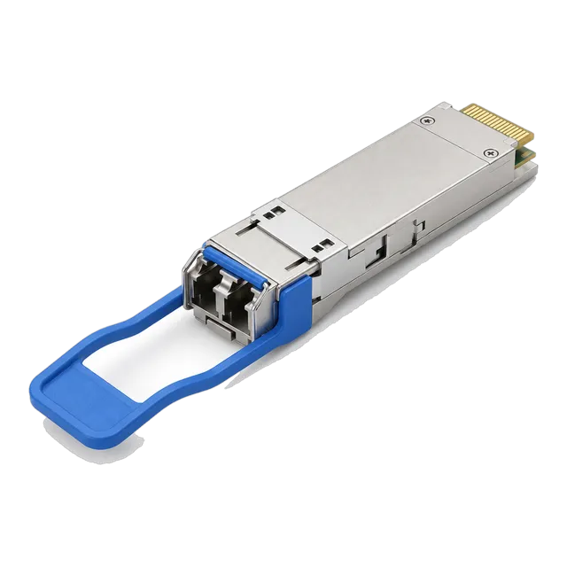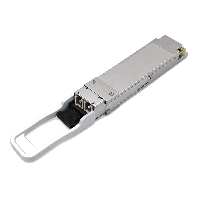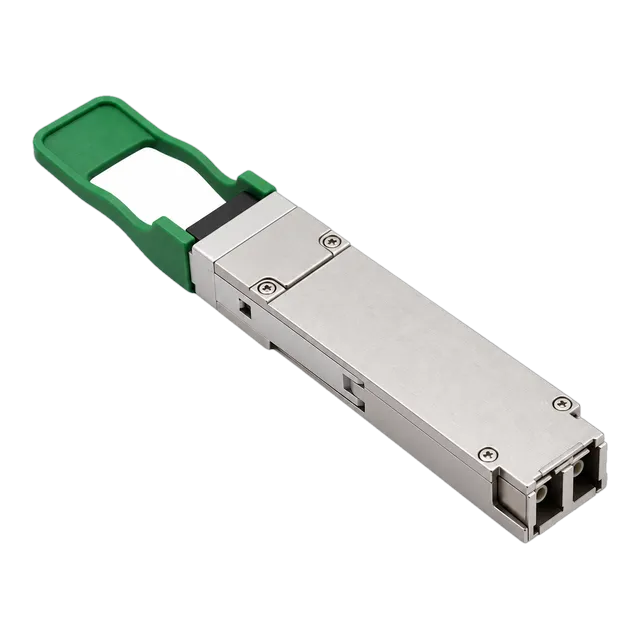
The QSFP 100G LR4 S optical transceiver delivers IEEE 802.3ba-compliant 100 Gbps transport over 10 km duplex single-mode fibre using four LAN-WDM wavelengths, requiring disciplined insertion loss budgets and accurate host EEPROM coding for reliable multi-vendor switching fabric deployment.
01Understanding the QSFP 100G LR4 S optical transceiver
A qsfp 100g lr4 s transceiver is a hot-pluggable optical module engineered for 100 Gigabit Ethernet (GbE) links spanning up to 10 kilometres over standard duplex single-mode fibre (SMF). Built in the Quad Small Form-factor Pluggable 28 (QSFP28) package, the 100G QSFP28 LR4 10km dual LC module aggregates four independent transmit and receive channels, each carrying a 25.78125 Gb/s optical lane to achieve the full 103.125 Gb/s aggregate line rate defined in IEEE 802.3ba Clause 88.
Network architects specify the qsfp 100g lr4 s module when interconnecting core switches, edge routers, and spine-leaf architectures across campus backbones or metro points of presence. Unlike parallel multi-fibre variants that demand 8-fibre or 12-fibre MPO/MTP cabling assemblies, the 100g lr4 architecture operates over a single pair of standard G.652 single-mode fibres terminated with dual LC optical connectors. The suffix "-S" denotes commercial-temperature, switch-optimised enterprise optics supporting standard Ethernet framing without optical transport network (OTN) wrapper overhead, lowering power draw and unit cost for data centre fabrics.
02QSFP 100G LR4 S optical architecture and LAN-WDM wavelengths
The qsfp 100g lr4 s transceiver multiplexes four discrete optical wavelengths onto an 800 GHz local area network wavelength division multiplexing (LAN-WDM) grid situated in the zero-dispersion window around 1310 nm. Internal optical multiplexing and demultiplexing micro-optics combine the four transmit beams into a single transmit fibre and unpack the four wavelengths at the receiver.
By adhering to ITU-T G.694.1 and IEEE 802.3ba Table 88-5, the LAN-WDM design confines optical transmission to a tight spectral band between 1295 nm and 1310 nm. This narrow spectrum minimizes chromatic dispersion penalties over 10 km of G.652 fibre without requiring electronic dispersion compensation. The four channel centre frequencies and wavelengths operate as follows:
- Lane L0: 1295.56 nm (optical frequency 231.4 THz, wavelength range 1294.53 nm to 1296.59 nm)
- Lane L1: 1300.05 nm (optical frequency 230.6 THz, wavelength range 1299.02 nm to 1301.09 nm)
- Lane L2: 1304.58 nm (optical frequency 229.8 THz, wavelength range 1303.54 nm to 1305.63 nm)
- Lane L3: 1309.14 nm (optical frequency 229.0 THz, wavelength range 1308.09 nm to 1310.19 nm)
Each optical path is isolated using thin-film interference filters with channel passbands exceeding 2 nm, ensuring optical crosstalk between adjacent channels remains below -30 dB across the operating temperature envelope.
03Transmitter optical specifications: EML lasers and launch power
Transmitters in a 100G QSFP28 LR4 module employ an array of four cooled Electro-absorption Modulated Lasers (EML) with integrated driver integrated circuits (ICs) to generate clean optical eye patterns at 25.78125 GBd. Distributed Feedback (DFB) base lasers paired with semiconductor electro-absorption modulators provide high extinction ratios and low chirp compared to directly modulated lasers (DML).
According to IEEE 802.3ba Clause 88.7.1, each lane in a 100g lr4 transceiver must deliver an optical modulation amplitude (OMA) between -1.3 dBm and +4.5 dBm, with an average launch power per lane constrained between -4.3 dBm and +4.5 dBm. The combined total average launch power across all four channels cannot exceed +10.5 dBm. Thermoelectric coolers (TEC) stabilize the laser junction temperatures within ±0.5°C to prevent thermal wavelength drift beyond the 800 GHz LAN-WDM grid passbands when ambient switch chassis temperatures fluctuate.
Engineers evaluating transmitter performance should verify that the transmitter and dispersion penalty (TDP) per lane does not exceed 2.2 dB, ensuring sufficient margin against chromatic dispersion degradation over unamplified 10 km glass spans.
04Receiver optical specifications: PIN photodiode and overload thresholds
The receiver subsystem in a qsfp28 lr4 module relies on an integrated optical demultiplexer paired with a four-channel positive-intrinsic-negative (PIN) photodiode array and transimpedance amplifiers (TIA). Optical signals entering the receive LC bore pass through spatial beam-separating optics that isolate the four LAN-WDM wavelengths and focus each channel onto its designated photodetector element.
The receiver sensitivity specification defined in IEEE 802.3ba Table 88-8 dictates a maximum receiver sensitivity (OMA) of -8.6 dBm per lane at a bit error ratio (BER) of 10-12 without forward error correction. On an average power basis, the receiver sensitivity threshold per lane is -10.6 dBm, while the input saturation overload point sits at +4.5 dBm average optical power. If optical input power exceeds the +5.5 dBm damage threshold on any lane, the photodiode risks lattice breakdown and permanent degradation.
Because the maximum total average receiver input power reaches +10.5 dBm across all four lanes, testing short patch cords in laboratory environments requires at least 5 dB to 7 dB of optical attenuation. Directly looping back a 100g lr4 optical transmitter into its own receiver without attenuators can overload the TIA and cause irreversible sensitivity degradation.
05Worked optical power budget calculation for a 10km link
A compliant 100GBASE-LR4 optical link provides a minimum channel insertion loss budget of 6.3 dB over 10 km of single-mode fibre. Calculating the power budget verifies whether field cabling infrastructure can reliably sustain transmission without bit errors.
To calculate link margin, subtract the worst-case receiver sensitivity from the minimum transmitter launch power, then deduct total passive plant losses including fibre attenuation, patch panel mating points, and fusion splices. The link power budget formula is:
Link Margin (dB) = Transmit Power Minimum (dBm) - Receiver Sensitivity (dBm) - Channel Insertion Loss (dB)
Consider a structured 9.2 km campus route terminated through three patch panels using standard ITU-T G.652.D single-mode fibre at 1310 nm:
- Fibre attenuation: 9.2 km × 0.35 dB/km = 3.22 dB
- Connector mating losses: 4 mated LC connector pairs (2 transceivers + 2 intermediate patch points) × 0.30 dB = 1.20 dB
- Fusion splices: 4 splices along the outside plant span × 0.05 dB = 0.20 dB
- Total passive insertion loss: 3.22 dB + 1.20 dB + 0.20 dB = 4.62 dB
Comparing this passive loss against the IEEE 802.3ba allocated channel budget of 6.3 dB yields an operating margin of 1.68 dB (6.3 dB - 4.62 dB). Because optical transmitters degrade over operational lifespans and patch connections collect microscopic particulate matter, maintaining an engineering safety margin of at least 1.5 dB to 2.0 dB is standard telecommunications practice. Engineers can model custom link lengths and connector counts using the MARS optical link budget calculator.
06Comparing 100G LR4 vs CWDM4 vs PSM4 optics
Selecting between 100G optical form factors depends on target link distance, existing single-mode or multimode structured cabling, and total module power dissipation. While the 100g lr4 transceiver addresses links up to 10 km using high-performance cooled EML lasers, alternative standards such as 100G CWDM4 and 100G PSM4 target shorter intra-data-centre distances at reduced initial procurement costs.
| Parameter | 100GBASE-LR4 | 100GBASE-CWDM4 | 100G PSM4 |
|---|---|---|---|
| Maximum Reach (m) | 10,000 m (10 km) | 2,000 m (2 km) | 500 m |
| Fibre Type | Duplex SMF (G.652) | Duplex SMF (G.652) | Parallel SMF (8 fibres) |
| Optical Connector | Dual LC | Dual LC | MPO-12 APC |
| Laser Type | Cooled 4x LAN-WDM EML | Uncooled 4x CWDM DML | Uncooled 4x 1310nm DFB |
| Wavelength Spacing | 800 GHz (~4.5 nm) | 20 nm CWDM grid | Single 1310 nm window |
| Host FEC Requirement | Optional (BER 10-12) | Mandatory (KR4 RS-FEC) | Mandatory (KR4 RS-FEC) |
| Module Power (W) | 3.5 W – 4.0 W | 2.5 W – 3.0 W | 2.0 W – 2.5 W |
As documented in our 100G optics SR4, CWDM4, LR4 and BiDi comparison, CWDM4 modules like the 100GBASE-CWDM4 QSFP28 2km transceiver offer lower power consumption for 2 km spans. However, they rely on 20 nm channel spacing spanning 1271 nm to 1331 nm, exposing outer channels to higher chromatic dispersion and requiring mandatory Reed-Solomon Forward Error Correction (RS-FEC) to close the link.
07QSFP28 LR4 power consumption and thermal dissipation
Standard qsfp28 lr4 optical transceivers operate within Power Class 4 (up to 3.5 W) or Power Class 5 (up to 4.0 W) as specified in SFF-8665. The higher power footprint compared to short-reach multimode optics stems from the active thermoelectric coolers required to stabilise the four discrete EML lasers on their LAN-WDM grid frequencies.
When deploying high-density switch fabrics equipped with 32 or 64 QSFP28 ports per rack unit (1RU), thermal management becomes critical. Inadequate front-to-back chassis airflow or clogged air filters can elevate module internal temperatures above their 70°C commercial threshold. Elevated thermal conditions trigger wavelength drift in the transmitter lasers, causing the light to shift outside the passband of the receiver optical demultiplexer and resulting in sudden frame loss.
Switch vendors categorise ports by thermal dissipation profiles. Network administrators must confirm that host switch ports support Power Class 5 optics before populating adjacent cages with 100G LR4 modules. In dense core switching environments, populating transceiver cages in a staggered checkerboard pattern can improve cold air circulation across front bezel intake paths.
08Host electrical interface and CAUI-4 retiming
A qsfp 100g module communicates with the host system processor across a 38-pin edge connector configured with four high-speed differential electrical transmit and receive lanes known as the CAUI-4 electrical interface. Defined in IEEE 802.3bm Annex 83E, each electrical lane carries a Non-Return-to-Zero (NRZ) signal running at 25.78125 Gb/s.
Because printed circuit board (PCB) traces between the host switch application-specific integrated circuit (ASIC) and the QSFP28 cage introduce high-frequency signal attenuation, modern 100G LR4 transceivers integrate dual clock and data recovery (CDR) retimers. These integrated circuits perform adaptive input equalization, jitter reduction, and output waveform reshaping in both the transmit and receive directions. The retimers lock onto the incoming 25.78125 Gb/s bitstream, stripping off high-frequency phase noise before driving the EML modulators.
If the host switch port is inadvertently configured for 40GBASE-LR4 operation, the CDR ICs fail to achieve phase lock because 40G requires four lanes running at 10.3125 Gb/s (XLPPI/XLAUI interface). Network engineers must verify that host port profiles are locked to 100 GbE native speed rather than 40G or 4x25G breakout modes.
09Digital diagnostic monitoring via SFF-8636 memory map
Digital diagnostic monitoring (DDM) for a 100g lr4 transceiver is implemented through a two-wire I2C serial interface structured around the SFF-8636 management interface specification. This register architecture allows network operating systems to query real-time physical operating parameters and issue threshold alarms.
Unlike single-channel SFP+ optics that report one transmit and receive optical power level, SFF-8636 allocates distinct two-byte register pairs for each of the four optical channels. Engineers querying the transceiver through command-line interfaces (CLI) can inspect:
- Transceiver case temperature: Reported in 1/256 degrees Celsius increments at I2C address 50h, Page 00h, Bytes 22–23.
- Internal supply voltage: Measured in 100 microvolt units at Bytes 26–27 (nominal 3.3 V rails).
- Laser bias current per lane: Reported in 2 microampere increments across Bytes 34–41 for Lanes 0 through 3.
- Transmitted optical power per lane: Calibrated in 0.1 microwatt increments across Bytes 42–49.
- Received optical power per lane: Calibrated in 0.1 microwatt increments across Bytes 50–57.
By tracking individual channel receive levels over time, network operators can identify dirty connector end faces or bent patch cords affecting a single LAN-WDM wavelength before bit errors impact upper-layer routing protocols.
10Forward error correction requirements for 100GBASE-LR4
The IEEE 802.3ba 100GBASE-LR4 physical layer standard specifies error-free operation at a pre-FEC bit error ratio (BER) of 10-12 without requiring host-level forward error correction. This native low-BER capability differentiates 100G LR4 from shorter-reach CWDM4 or SR4 standards, which rely on Clause 91 RS-FEC (528,514) to correct raw channel bit error ratios of 5 × 10⁻⁵ down to acceptable thresholds.
Because RS-FEC introduces roughly 100 to 250 nanoseconds of processing latency per encoding and decoding cycle, disabling FEC on 100GBASE-LR4 links reduces overall transmission latency for high-frequency trading networks, real-time supercomputing clusters, and uncompressed broadcast video streams. However, most contemporary enterprise switches default to having Clause 91 RS-FEC enabled globally on 100G QSFP28 ports.
When connecting two switch platforms across a 10 km 100G LR4 span, engineers must ensure both ends share an identical FEC configuration. If one switch port is configured with fec cl91 or fec auto while the remote switch port has FEC disabled, the CAUI-4 link will fail to align PCS (Physical Coding Sublayer) 66-bit code blocks, preventing port link-up even when physical optical power levels fall well within specification.
11Single-mode fibre dispersion limits under ITU-T G.652
Chromatic dispersion in standard ITU-T G.652 single-mode fibre is the primary physical constraint governing 100 Gbps optical reaches beyond 10 kilometres. At 1310 nm, G.652.D fibre exhibits a chromatic dispersion coefficient between -3.0 and +3.0 ps/(nm·km), with the zero-dispersion wavelength situated between 1300 nm and 1324 nm.
The LAN-WDM wavelength grid utilized by the qsfp 100g lr4 s transceiver places channel L0 at 1295.56 nm and channel L3 at 1309.14 nm. Because L0 sits on the negative dispersion slope and L3 sits close to the zero-dispersion crossing point, each channel undergoes slightly different temporal pulse spreading across a 10 km span. Standard IEEE 802.3ba compliance caps the maximum dispersion penalty at 2.2 dB per lane across the full 10 km reach.
For link extensions beyond 10 km, standard 100G LR4 optics cannot overcome cumulative dispersion and attenuation without amplification. Network operators needing to span 20 km to 100 km over existing fibre pairs should evaluate specialized long-haul optics, such as the 100G QSFP28 eZR4 100km transceiver, which incorporates integrated semiconductor optical amplifiers (SOA) and avalanche photodiode (APD) receivers.
12Selecting between standard 100G LR4 and extended-reach variants
When specifying optics for inter-site backbones, engineers must distinguish between standard 10 km 100GBASE-LR4 optics and extended-reach 20 km to 40 km derivatives that share similar LC duplex interfaces. Selecting the incorrect variant can lead either to link starvation from excessive attenuation or receiver damage caused by optical overdrive.
Extended-reach 100G LR4-20km and 100GBASE-ER4-Lite modules employ the identical 800 GHz LAN-WDM wavelength grid but substitute APD receivers in place of PIN photodiodes. APD detectors provide internal carrier multiplication, improving receiver sensitivity from -8.6 dBm down to -15.0 dBm or lower. However, APD receivers have strict optical overload limits typically capped at -3.0 dBm. Connecting an extended-reach module across a short 2 km run without inline optical attenuators will damage the APD photodiode array.
Review the comprehensive architectural breakdown in our QSFP28 transceiver engineering selection guide and browse the complete 100G QSFP28 transceiver range to align reach requirements, laser types, and optical attenuation limits with specific physical plant assets.
13Technical RFQ specification checklist for enterprise and carrier procurement
Procuring a high-reliability 100g lr4 transceiver requires precise mechanical, optical, and EEPROM parameters in request-for-quotation (RFQ) documentation to prevent grey-market mismatches or firmware rejection by host switches. Sourcing teams can copy and incorporate the following engineering parameters directly into procurement line items:
- Form Factor: QSFP28 (SFF-8665 compliant, 38-pin gold edge connector).
- Optical Standard: IEEE 802.3ba 100GBASE-LR4 and IEEE 802.3bm.
- Signalling Rate: 103.125 Gb/s aggregate (4 lanes × 25.78125 Gb/s NRZ).
- Wavelength Plan: 4-lane LAN-WDM (1295.56 nm, 1300.05 nm, 1304.58 nm, 1309.14 nm per ITU-T G.694.1).
- Optical Interface: Duplex LC female connector receptacle conforming to IEC 61754-20.
- Transmitter Type: 4-channel cooled EML with internal CDR retimers; average launch power per lane -4.3 dBm to +4.5 dBm.
- Receiver Type: PIN photodiode array with internal CDR; sensitivity better than -8.6 dBm OMA per lane; overload margin +4.5 dBm minimum.
- Power Consumption: Maximum 3.5 W (Power Class 4) or 4.0 W (Power Class 5) at nominal 3.3 V DC supply.
- Digital Diagnostics: Real-time DDM/DOM per SFF-8636 with per-channel Tx/Rx power, bias, temperature, and voltage telemetry.
- Host Platform Coding: Multi-vendor target switch EEPROM verification (Table 00h and Upper Page 00h MSA data) matching host vendor vendor-ID strings, checksum algorithms, and security handshakes.
14Practical deployment and link turn-up verification steps
Commissioning a qsfp 100g lr4 s optical link requires a systematic physical inspection and logical turn-up sequence to prevent optic damage and isolate cabling faults. Field engineers should follow these sequential verification steps:
- Clean and inspect fibre end faces: Use an automated video inspection microscope to verify that both LC connector ferrules meet IEC 61300-3-35 Zone A core inspection criteria. Clean with a dry optical ferrule click-cleaner prior to mating.
- Measure received optical power before insertion: Connect the incoming single-mode fibre to an optical power meter calibrated at 1310 nm. Verify that aggregate incoming optical power does not exceed +4.5 dBm to protect the transceiver PIN receiver from optical overload.
- Seat the QSFP28 transceiver firmly: Align the module with the cage guides and push until the mechanical bail latch engages with a positive click. Confirm the pull-tab rests flat against the module bezel to prevent chassis airflow turbulence.
- Verify host EEPROM recognition: Execute switch CLI commands (such as
show inventoryorshow interfaces transceiver detail) to confirm the host operating system correctly reads the vendor identifier, serial number, and MSA part profile. Details on memory maps and coding are available in our guide to transceiver coding and EEPROM compatibility. - Inspect per-lane DDM levels: Review real-time optical power diagnostics across all four lanes. Transmit power should read between -4.3 dBm and +4.5 dBm per channel; received power should sit comfortably above -8.6 dBm with balanced levels across all four LAN-WDM lanes.
- Validate bit error and FEC statistics: Monitor interface error counters for 15 minutes. Check that no CRC alignment errors, PCS sync loss alarms, or uncorrectable FEC frame discards accumulate during line-rate traffic.
For multi-switch deployment architectures, contact our technical team at optical module engineering support to verify transceiver host platform coding and custom link budget requirements before ordering production volumes.
15Frequently asked questions
What is the difference between QSFP 100G LR4 and 100G CWDM4?
A QSFP 100G LR4 transceiver supports 10 km reaches using cooled EML lasers across an 800 GHz LAN-WDM grid (1295-1310 nm) over duplex single-mode fibre. A 100G CWDM4 transceiver reaches up to 2 km using uncooled DML lasers across a 20 nm coarse WDM grid (1271-1331 nm) and requires mandatory host RS-FEC.
Does a 100GBASE-LR4 link require RS-FEC enabled on the switch?
No, standard IEEE 802.3ba 100GBASE-LR4 optics achieve a bit error ratio under 10^-12 without forward error correction. However, both switch ports must share identical FEC settings; if one end enables Clause 91 RS-FEC while the other disables it, the physical link will fail to establish frame synchronization.
Can a QSFP 100G LR4 S optic connect to a 40G LR4 port?
No, a 100G LR4 optical transceiver cannot link with a 40GBASE-LR4 transceiver. Although both optics use duplex LC connectors and LAN-WDM wavelengths near 1310 nm, 100G LR4 runs at 25.78125 Gb/s per lane, whereas 40G LR4 runs at 10.3125 Gb/s per lane, preventing clock and data recovery lock.
What is the maximum power consumption of a QSFP28 100G LR4 module?
A QSFP28 100G LR4 transceiver typically draws between 3.5 W (Power Class 4) and 4.0 W (Power Class 5). The higher power consumption relative to short-reach transceivers results from the thermoelectric coolers required to maintain precise operating temperatures for the four EML lasers.
What is the minimum optical attenuation needed when looping back 100G LR4?
Direct loopback testing of a 100G LR4 optic requires at least 5 dB to 7 dB of optical attenuation. The maximum launch power per lane can reach +4.5 dBm, which exceeds the receiver overload threshold and risks degrading the sensitive PIN photodiode receiver without inline optical attenuators.
Can QSFP 100G LR4 S optics operate over multimode fibre?
No, 100GBASE-LR4 optics cannot operate over multimode fibre. The modal dispersion of OM3 or OM4 multimode fibre severely degrades the 25.78125 Gb/s optical signals within a few metres, and the optical launch optics are specifically aligned for 9/125 micrometre single-mode fibre cores.
Technical review note: confirm model-specific specifications with the product datasheet and the intended host documentation. Product images and application photographs are illustrative.
Discuss this with our team