A duplex cable provides dedicated, bidirectional transmission channels over two distinct optical strands, offering lower initial transceiver component costs and straightforward debugging compared to single-fibre BiDi architectures, provided link budget and patch-field polarity are properly managed.
01What is a duplex cable in optical networking?
A duplex cable is a two-strand optical transmission assembly designed to support simultaneous, bidirectional communication by dedicating one strand to transmit (Tx) and the other to receive (Rx). Standardised under TIA-568 and ISO/IEC 11801, duplex patch cords and trunk assemblies eliminate internal crosstalk by physically separating the outbound and inbound optical signals onto independent glass cores. In high-density enterprise, data centre, and service provider networks, duplex fiber cable builds form the backbone of structured horizontal cross-connects and backbone links. Each strand terminates into standard ferrule connectors—typically LC, SC, or ST—allowing direct pairing with dual-receptacle optical transceivers. By maintaining dedicated unidirectional pathways, a duplex cable ensures consistent insertion loss performance without requiring internal passive wavelength filters inside the optoelectronics.
02How duplex transmission works: Tx and Rx physical separation
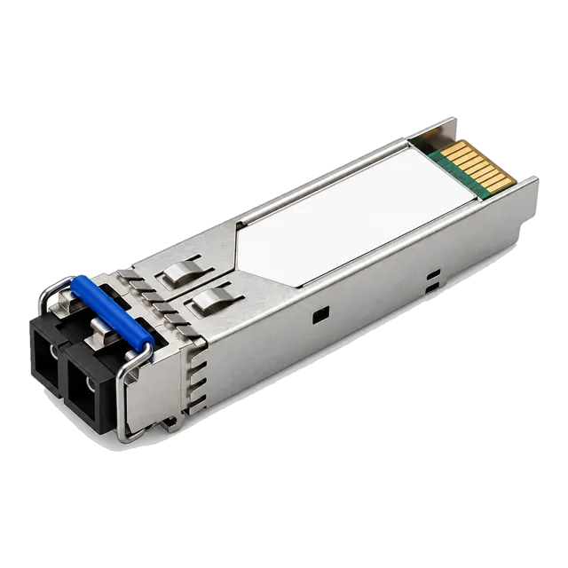
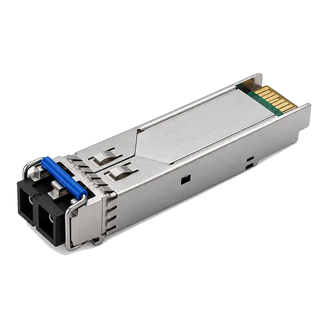
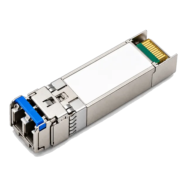
Duplex optical transmission operates by isolating forward and reverse signal streams onto dedicated parallel paths within the physical layer. Inside a standard dual-bore Small Form-Factor Pluggable (SFP) module, a Transmitter Optical Sub-Assembly (TOSA) converts electrical host signals into photon pulses, while a separate Receiver Optical Sub-Assembly (ROSA) detects incoming light and translates it back into electrical currents. When using a duplex cable, the TOSA at Node A couples into strand 1, terminating at the ROSA of Node B. Conversely, Node B emits from its TOSA into strand 2 to reach the ROSA at Node A. This architectural isolation bypasses the near-end optical reflection penalties that affect single-strand systems. Because both channels operate on the identical nominal wavelength—such as 850 nm for multimode or 1310 nm for single-mode—transceiver bill-of-materials costs remain significantly lower than complex multiplexed assemblies.
03Duplex fiber cable vs simplex and BiDi architectures
The choice between duplex fiber cable and simplex bidirectional (BiDi) transmission represents a strategic trade-off between cable plant utilisation and transceiver complexity. Simplex BiDi transceivers use integrated wavelength division multiplexing (WDM) diplexers to combine Tx and Rx onto a single optical strand, typically transmitting at 1310 nm and receiving at 1490 nm or 1550 nm. While BiDi doubles the data-carrying capacity of existing buried or leased fiber runs, it increases transceiver per-unit cost and requires strict complementary pairing of upstream and downstream units. A standard duplex cable uses two identical transceivers at both ends operating at the exact same wavelength, simplifying spare parts inventory and warehouse management. For greenfield campus deployments and short-reach data centre interconnects where multi-core fiber runs are accessible, duplex infrastructure remains the default industry architecture due to its operational simplicity and lower electronics expenditure.
04Single-mode duplex cable vs multimode duplex cable
Single-mode duplex cable and multimode duplex cable are distinguished by their glass core diameters, optical dispersion characteristics, and supported transmission spans. Single-mode fiber (OS2) features a narrow core diameter of 9 µm conforming to ITU-T G.652.D or bend-insensitive G.657.A1 specifications, supporting long reaches up to 80 km or more using Fabry-Perot (FP) or Distributed Feedback (DFB) laser sources at 1310 nm and 1550 nm. Multimode fiber (OM3, OM4, OM5) employs a wider 50 µm graded-index core specified under ISO/IEC 11801, engineered for cost-effective Vertical-Cavity Surface-Emitting Lasers (VCSEL) operating at 850 nm over spans up to 400 m. While multimode transceivers offer reduced initial hardware procurement expense for short-reach top-of-rack patching, single-mode duplex cable avoids modal dispersion altogether, providing forward-proof bandwidth scaling from 1.25G up to 100G and beyond across campus backbones.
05Standard connector types for duplex fiber optic links
Duplex optical links rely primarily on LC and SC connector interfaces engineered with precision ceramic ferrules to achieve low insertion loss. The Lucent Connector (LC) utilises a compact 1.25 mm ferrule housed in an RJ45-style latching body, making it the universal standard for SFP, SFP+, SFP28, and QSFP28 duplex interfaces. The Subscriber Connector (SC) features a 2.5 mm push-pull coupling ferrule, widely adopted in telecommunications distribution frames and industrial media converters. For high-density switch environments, LC uniboot designs integrate both strands into a single round 2.0 mm jacket with a dual-ferrule housing, cutting patch field bulk by 50 percent compared to traditional zipcord cabling. Engineers specifying connectors must consult our SFP connector types guide to ensure proper mechanical retention and ferrule end-face geometry.
06Managing polarity: A-to-B versus A-to-A duplex patch cords
Optical polarity ensures that the transmitter on one piece of network equipment couples directly into the receiver on the opposite end. ANSI/TIA-568-C.3 defines standard duplex cable polarity configurations, primarily Type-A (straight-through) and Type-B (crossover). Standard duplex patch cords employ an A-to-B crossover polarity, where Position A at one end maps to Position B at the far end, automatically matching the transceiver Tx bore with the remote Rx bore. If an A-to-A patch cord is inadvertently deployed across a direct link, Tx transmits into Tx, leading to an immediate link-down condition. In complex structured cabling containing multiple patch panels, cassetted MPO/MTP backbones, and intermediate cross-connects, maintaining an odd number of logical flips across the end-to-end channel ensures proper signal delivery without requiring field connector modifications.
07Duplex cable specifications across Ethernet speeds
Optical Ethernet specifications establish rigorous physical-medium requirements for duplex cabling across varying data rates, link distances, and fiber types. The following engineering comparison illustrates standard parameters governing duplex links from 1.25 Gbps to 100 Gbps under IEEE 802.3 standards:
| Ethernet Standard | IEEE Clause | Data Rate (Gbps) | Cable Type | Wavelength (nm) | Max Reach (km) | Max Channel Loss (dB) |
|---|---|---|---|---|---|---|
| 1000BASE-LX | Clause 38 | 1.25 | OS2 Duplex | 1310 | 10.0 | 4.50 |
| 10GBASE-LR | Clause 52 | 10.3125 | OS2 Duplex | 1310 | 10.0 | 6.20 |
| 25GBASE-SR | Clause 114 | 25.78125 | OM4 Duplex | 850 | 0.1 | 1.90 |
| 25GBASE-LR | Clause 114 | 25.78125 | OS2 Duplex | 1310 | 10.0 | 8.40 |
| 100GBASE-LR4 | Clause 88 | 103.125 | OS2 Duplex | 1295–1309 (WDM) | 10.0 | 6.30 |
| 100GBASE-eZR4 | Proprietary MSA | 103.125 | OS2 Duplex | 1295–1309 (LWDM) | 100.0 | 28.00 |
As demonstrated across these physical layer parameters, operating high-speed channels such as 25G or 100G requires careful alignment between transceiver transmit power windows and cable plant loss characteristics to prevent bit-error-rate degradation.
08Calculating an optical link budget for a duplex cable run
A complete optical link budget calculation verifies whether the total channel insertion loss falls safely within the transceiver dynamic range while preserving an engineering safety margin. To evaluate a single-mode duplex link, engineers aggregate fiber attenuation, connector insertion losses, and fusion splice losses. Consider an enterprise campus link deploying a 2.5G single-mode 1310nm 20km duplex transceiver over 14 km of OS2 duplex cable. Transceiver specifications establish a minimum launch power (Tx Min) of -5.0 dBm and an optical receiver sensitivity (Rx Sens) of -20.0 dBm, yielding an available optical power budget of 15.0 dB. Link parameters include:
- Fiber cable attenuation at 1310 nm: 14 km × 0.35 dB/km = 4.90 dB
- Four mated LC connector pairs: 4 × 0.30 dB = 1.20 dB
- Six fusion splices across the span: 6 × 0.08 dB = 0.48 dB
- Total passive link attenuation: 4.90 dB + 1.20 dB + 0.48 dB = 6.58 dB
- Engineering safety margin: 15.0 dB available - 6.58 dB loss = 8.42 dB optical margin
An 8.42 dB margin comfortably exceeds the recommended 3.0 dB buffer for component ageing, ensuring robust link operation. Network designers can cross-verify complex calculations using our online link budget calculator before procurement.
09Selecting duplex transceivers: SFP, SFP28, and QSFP28 modules
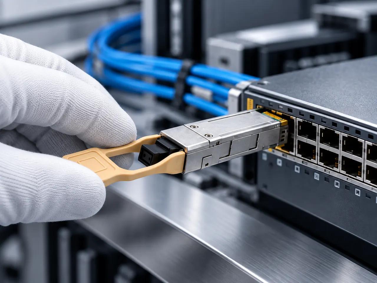
Selecting the appropriate duplex optical module requires matching the transceiver interface with the installed fiber infrastructure and switch backplane capabilities. Standard 1.25G Gigabit links commonly leverage dual-fiber transceivers, such as the 1.25G SFP 1310nm 10km duplex module, to connect edge switches and distribution frames. At 25G line rates, modules like the 25GBASE-LR SFP28 1310nm 10km duplex transceiver leverage Reed-Solomon Forward Error Correction (RS-FEC) to maintain link integrity over standard single-mode duplex cable plants. For ultra-long-reach transport, high-order QSFP28 optical transceivers integrate Internal Semiconductor Optical Amplifiers (SOA) and Lanewavelength Division Multiplexing (LWDM) over duplex LC ports, allowing operators to span up to 100 km on OS2 glass without external dispersion compensation equipment.
10When to deploy duplex cable versus single-fiber BiDi optics
Deciding whether to deploy duplex cable or single-fiber BiDi optics hinges on duct capacity, fiber leasing fees, and operational deployment scopes. The following decision matrix provides engineering teams with structured criteria for infrastructure procurement:
| Evaluation Criterion | Duplex Cable Architecture | BiDi Optical Architecture |
|---|---|---|
| Fiber Strand Consumption | Two strands per full-duplex link | One strand per full-duplex link |
| Transceiver Hardware Cost | Standard, lower unit cost | 15% to 40% higher unit cost |
| Spares Management | Single SKU per link type | Paired complementary SKUs (e.g., complementary Tx and Rx wavelengths) |
| Leased Fiber Environments | Higher ongoing operational expenditure | Halves monthly dark fiber recurring costs |
| Troubleshooting Complexity | Straightforward (isolate Tx or Rx strand) | Requires WDM-aware OTDR and optical power meters |
| Connector Alignment | Dual LC or SC duplex clips | Simplex LC or SC single-bore receptacles |
Where conduit space is unrestricted, duplex cable delivers straightforward maintenance and lower transceiver replacement costs across enterprise premises. For a comprehensive comparison of transceiver operating models, consult our technical analysis on BiDi transceiver engineering and link budgets.
11Diagnosing duplex cable link failures with DDM and OTDR
Systematic troubleshooting of duplex links isolates whether an issue stems from patch cord damage, contamination, or transceiver degradation. Modern transceivers incorporate Digital Diagnostic Monitoring (DDM) conforming to SFF-8472 specifications, providing real-time telemetry including Tx power output, Rx optical power input, internal temperature, and laser bias current. If DDM telemetry reveals normal Tx power at Node A but zero or marginal Rx power at Node B, engineers should proceed with the following sequence: clean and inspect both LC ferrule end-faces with an IEC 61300-3-35 compliant scope; verify A-to-B polarity continuity using a visual fault locator (VFL); and measure total channel loss using an optical power meter. If losses exceed calculated budgets, an Optical Time-Domain Reflectometer (OTDR) operating at 1310 nm or 1550 nm will pinpoint high-loss microbends, pinched outer jackets, or defective fusion splices along the duplex fiber cable run.
12Duplex cable procurement checklist for technical RFQs
Procurement teams and network engineers must specify complete mechanical, optical, and environmental requirements when preparing a Request for Quotation (RFQ) for duplex infrastructure. An incomplete bill of materials frequently results in mismatched polarities, incorrect jacket ratings, or excessive optical attenuation. Copy and utilise the following technical checklist during project scoping:
- Optical Fiber Standard: Specify OS2 (G.652.D or G.657.A1 bend-insensitive) for single-mode, or OM4 for multimode.
- Cable Construction: Designate zipcord (figure-8) for standard patch panels, or round uniboot (2.0 mm or 3.0 mm) for high-density switches.
- Connector Configuration: Specify LC-Duplex to LC-Duplex, SC-Duplex, or hybrid configurations with ceramic ferrules.
- Polarity Standard: Require ANSI/TIA-568-C.3 Type-B (crossover A-to-B) factory alignment, with detachable duplex housing clips.
- Ferrule End-Face Polish: Designate Ultra Physical Contact (UPC, blue, return loss ≤ -50 dB) or Angled Physical Contact (APC, green, return loss ≤ -60 dB).
- Jacket Material Rating: Mandate Low Smoke Zero Halogen (LSZH) for European/IEC compliance, or OFNP (Plenum) / OFNR (Riser) for North American NFPA standards.
- Maximum Optical Insertion Loss: Ensure factory test reports certify insertion loss ≤ 0.30 dB per connector pair at operational wavelengths.
- Temperature Performance: Match the commercial (0 to +70 °C) or industrial (-40 to +85 °C) rating of mating transceivers.
Engineering teams requiring custom jacket materials, specialized uniboot clips, or factory-coded transceivers can consult our specialists via our direct RFQ contact channel.
13Frequently asked questions
What is the primary difference between a duplex cable and a simplex cable?
A duplex cable integrates two separate optical fiber strands within a single jacket assembly to enable simultaneous, bidirectional transmission. In contrast, a simplex cable contains only one optical strand, supporting unidirectional data flow unless paired with specialized bidirectional (BiDi) transceivers using wavelength division multiplexing.
Can you use a duplex cable with BiDi transceivers?
Yes, but it is physically redundant. A single BiDi transceiver requires only one optical strand for bidirectional data transport. If connected via a duplex cable, one strand handles the complete data link while the second strand remains unlit, unless used as an unconnected cold spare.
What does A-to-B mean on a duplex fiber patch cord?
A-to-B denotes crossover polarity under ANSI/TIA-568 specifications. This standard cross-connects the transmitter (Position A) at one end of the patch cord directly into the receiver (Position B) at the opposing end, ensuring proper optical alignment between mated transceivers without field modification.
Why are single-mode duplex cables yellow while multimode cables are aqua or magenta?
Standard jacket colours are defined by TIA-598-C for rapid field identification. Single-mode (OS2) duplex cables use yellow outer jackets, while multimode laser-optimised OM3 and OM4 cables use aqua and Erika violet (magenta) respectively, preventing accidental cross-connection of mismatched core diameters.
What is an LC uniboot duplex cable?
An LC uniboot duplex cable encloses two independent optical fibers inside a single round 2.0 mm or 3.0 mm jacket terminated with a unified dual-ferrule connector. This reduces patch cable volume by up to 50 percent, improving airflow and cabinet density in enterprise racks.
Technical review note: confirm model-specific specifications with the product datasheet and the intended host documentation. Product images and application photographs are illustrative.
Discuss this with our team