Single-fiber BiDi halves strand use, but only if every drop is planned as a matched wavelength pair with each direction budgeted separately and the far-end enclosure rated for its environment.
01The connection brief
Single-fiber access connectivity uses one strand per link instead of two, sending the two directions on different wavelengths. This page sets out how such a link is planned. It is an application concept and a reference method, not an account of a delivered network, and it names no operator, site or result.
The typical brief is a set of subscriber or endpoint drops served from one aggregation point, where the duct or the existing cable simply does not hold enough strands for dual-fiber working. The planning question is whether the available strand per drop, the measured route length and the required data rate can be closed with a standard BiDi optical class, and what has to be documented so the answer is repeatable rather than a one-off guess.
02The design inputs
Record the number of drops, the measured length of the longest and shortest route, and the strand assignment for each drop. Record what terminates each end: a switch with SFP cages at the aggregation point, and either another switch, a media converter or a customer device at the far end.
Capture the required rate per drop today and at the next step, because a gigabit drop and a 2.5 gigabit drop use different module families on the same fiber. Note the connector type physically present, since single-fiber modules exist with both simplex LC and simplex SC interfaces and the installed panel decides which is convenient. Finally, record the environment at the far end, which is frequently a cabinet or a pole enclosure rather than a room.

03The topology and optical path
The topology is a hub and spoke: one aggregation switch, one strand per drop, one endpoint per strand. Each strand carries an upstream wavelength and a downstream wavelength, so the module at the hub and the module at the endpoint are complementary rather than identical.
Write out the optical path for the longest drop as a chain: hub module, simplex jumper, hub panel, outside plant strand with its splices, street or building panel, simplex jumper, endpoint module. Splices count at about 0.1 dB and mated connector pairs at 0.3 to 0.75 dB. Because a single strand carries both directions, a strand fault removes the link entirely, which makes the strand record and the splice record more operationally important than on a dual-fiber design.
04Product families to evaluate
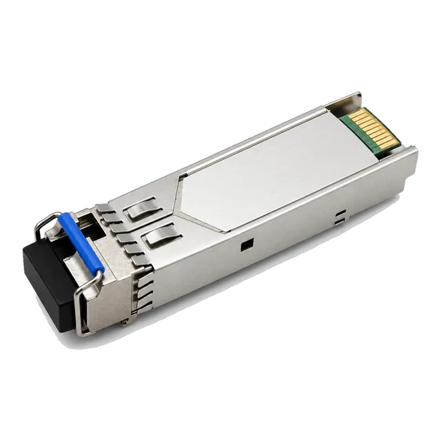
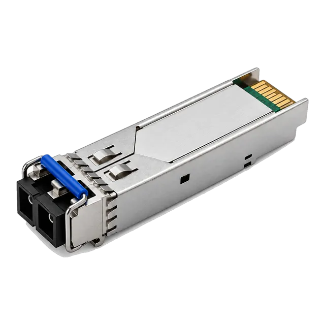
For gigabit drops the 1.25G SFP BiDi listings are the core family. The 1.25G BiDi Single-Fiber SFP Transceiver 1310nm/1550nm 20km covers the common access distance with a simplex LC interface, the 1.25G SFP BiDi Optical Module 20km 1310nm/1550nm SC variant suits installed SC panels, and the 1.25G BiDi SFP 1310nm/1490nm 60km LC DDM Single-Fiber module addresses longer routes.
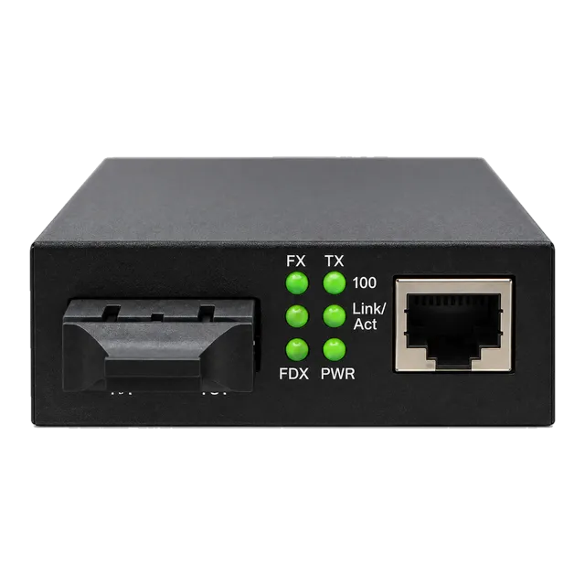
Where the drop must run at 2.5 gigabit, the 2.5G BiDi SFP-2.5G-BX120 Single-Fiber 1490/1550nm 120km module is the relevant long-reach option. At the far end, where the customer device only has copper, the 1.25G SFP UTP PoE Media Converter or the 10/100/1000 Gigabit Fiber Media Converter converts the drop to an RJ45 interface, with the choice between them decided by whether the endpoint also needs power.
05Link budget and reach considerations
BiDi budgets are calculated in the same way as dual-fiber budgets, with one addition: the two directions use different wavelengths and therefore different attenuation coefficients, so each direction is calculated separately. Use roughly 0.35 dB/km at 1310 nm and roughly 0.22 dB/km at 1550 nm, then add mated pairs at 0.3 to 0.75 dB and splices at about 0.1 dB.
Compare each direction against the launch power and sensitivity figures in the datasheet for that end of the pair, and keep about 3 dB of unallocated margin. The 1310 nm direction is usually the tighter of the two on a long route, so a pair that closes comfortably downstream may still be marginal upstream. Calculate both before selecting the reach class.
06Environment and power
Access endpoints often sit outside a controlled room. A street cabinet, a pole box or a building entrance enclosure sees a far wider temperature swing than a data room, so the industrial grade of minus 40 to 85 degrees Celsius is frequently the right specification for the endpoint even when the hub end stays on the commercial 0 to 70 degrees Celsius grade.
Power at the far end is the other constraint. A media converter needs a local supply, and if the drop feeds a device that also needs power, a converter with PoE output can remove one power supply from the enclosure. Record the available supply voltage, whether it is backed up, and how much heat the enclosure can dissipate.
07Validation and acceptance
Test the strand before fitting modules. A light source and power meter at both working wavelengths gives the actual loss per direction, which is the figure the budget calculation should have predicted. On routes with splices, an OTDR trace documents where they are.
With the pair fitted, read digital diagnostics at both ends and check that received power sits inside the datasheet window rather than merely above sensitivity. Confirm that the upstream and downstream modules are the matched complementary types, which is easiest to verify from the DDM wavelength reporting rather than from the label. Finish with a traffic soak at the required rate and record the results as the baseline for the drop.
08Procurement and BOM
The defining procurement rule for single-fiber working is that modules are bought in matched pairs. An order for a quantity of one part number will produce a box of identical modules that cannot talk to each other, so the BOM must list the upstream type and the downstream type as separate lines with equal quantities.
Beyond that, list simplex jumpers in the connector style that matches the installed panels, media converters and their power supplies where the far end is copper, and the temperature grade required per location. Spares should be held as pairs for the same reason. Coding for the hub switch is confirmed per platform and recorded in the same sheet.
09Common mistakes
Ordering a single BiDi part number for both ends is the most common and the most costly error, because the modules arrive correct and still will not link. Second is calculating only one direction of the budget and being caught by the higher attenuation of the 1310 nm path on a long route.
Third is fitting simplex modules into a duplex jumper, which physically works at the module but leaves the second strand dark and confuses later fault finding. Fourth is specifying commercial grade optics for a pole or street enclosure. Fifth is forgetting that a single strand carries both directions, so a drop has no inherent resilience and any redundancy has to be designed in at the topology level.
10Next step
Produce a drop schedule listing each endpoint, its strand assignment, its measured route length, the required rate and the enclosure type at the far end. Add the hub switch model and software release, and the connector style of the installed panels.
With that in hand, add candidate items from the 1.25G SFP, 2.5G SFP and media converter listings to an inquiry list, marking clearly which quantity is the upstream type and which is the downstream type. The project worksheet provides the same fields if no schedule exists yet. Since this is a planning concept rather than a built network, the reach classes and the budget should be recalculated against the real strand measurements before any order is placed.
11Design inputs to document
| Design input | What to record |
|---|---|
| Drop schedule | Endpoint list with strand assignment and measured route length. |
| Required rate per drop | Gigabit or 2.5 gigabit now, and the expected next step. |
| Connector style | Simplex LC or simplex SC, matching the installed panels. |
| Wavelength plan | Which end is upstream and which is downstream, per drop. |
| Far-end equipment | Switch, media converter or customer device, and its interface. |
| Enclosure environment | Indoor room, street cabinet or pole box, to set the temperature grade. |
| Far-end power | Available supply, backup status and whether PoE output is needed. |
12Planning bill of materials
| Item | Configuration | Quantity |
|---|---|---|
| 1.25G BiDi SFP, upstream wavelength | 1310/1550 nm, simplex LC, single-mode, 20 km class, DDM | 1 per drop |
| 1.25G BiDi SFP, downstream wavelength | Complementary wavelength assignment to the upstream unit | 1 per drop |
| 2.5G BiDi SFP long-reach | 1490/1550 nm, simplex LC, single-mode, 120 km class | 2 per long drop, matched pair |
| Gigabit fiber media converter | SFP or fixed fiber port to RJ45, PoE output where required | 1 per copper endpoint |
| Simplex patch cords | LC or SC to match the installed panel, single-mode | 2 per drop |
Planning quantities only. The final bill of materials is confirmed with your quotation.
13Frequently asked questions
Why do BiDi modules have to be ordered in pairs?
Because each module transmits on one wavelength and receives on the other. Two identical modules would both transmit on the same wavelength and neither would hear the other. The planning BOM therefore lists the upstream type and the downstream type as separate lines with equal quantities, and spares are held as pairs so a single replacement never strands its partner.
Does single-fiber working reduce reach?
Not inherently. Reach is set by the optical class, and BiDi families are offered across short access distances and long metro distances alike. What changes is that the two directions use different wavelengths with different attenuation, so each direction is budgeted separately and the 1310 nm path is usually the tighter one on a long route.
Can a media converter sit in an outdoor cabinet?
Only if its temperature rating covers the enclosure. Commercial equipment rated 0 to 70 degrees Celsius is often unsuitable for a sealed street cabinet in summer. Record the enclosure type and its ventilation, then specify equipment whose rating covers the worst case, using the industrial minus 40 to 85 degrees Celsius grade where the margin is thin.
What happens if the single strand is damaged?
The whole link stops, in both directions at once. A single-fiber drop has no inherent resilience, so any redundancy has to come from the topology, for example a second physically diverse drop or a wireless backup path. This is a design decision to record at the start rather than an issue to discover during the first duct failure.
Technical review note: confirm model-specific specifications with the product datasheet and the intended host documentation. Product images and application photographs are illustrative.
Discuss this with our team