Plan a 100G link from the installed fiber path outward: grade, length, connectors and polarity first, then the optical class, then the coding confirmed per host platform.
01The connection brief
This page describes how a short-reach 100G link between two switch ports is planned. It is an application concept written as a reference method, not a record of a delivered project, so it contains no site, no customer and no measured result.
The starting point is the pair of host platforms at each end, the cage type each one presents, and the physical route between them. A 100G interconnect inside a data hall usually joins a leaf switch to a spine switch, or a top-of-rack switch to an end-of-row aggregation device. Before any part number is discussed, the plan records what the ports are, whether cabling is already installed, and how long the route really is once slack, patch panels and vertical rise are counted. Everything below turns those facts into a defensible bill of materials.
02The design inputs
Collect the exact host model and software release at both ends, because module coding and the accepted transceiver behaviour are platform-specific and are confirmed per platform rather than assumed. Record the fiber grade in the route, distinguishing OM3 from OM4, and either of those from single-mode. Obtain the installed length rather than the straight-line distance between racks. Note the connector arrangement: MPO-12 for parallel optics, duplex LC for a wavelength-multiplexed interface. Count patch panels, splices and any building cross-connect in the path, since each mated pair adds loss. Capture the free port budget on each switch, the power and cooling headroom in the chassis, and whether the same port must support a later speed change. These inputs decide the shortlist long before price does.

03The topology and optical path
Draw the path as a chain of physical elements rather than as a line on a rack elevation. A typical parallel-optics channel runs module, MPO jumper, panel adapter, MPO trunk, panel adapter, MPO jumper, module. Each adapter is a mated pair and each mated pair is a loss element. Polarity has to be declared explicitly: the installed method, usually A, B or C in the structured-cabling sense, determines which jumpers and cassettes are ordered, and mixing methods is the most common cause of a dead parallel link.
For a duplex single-mode path the chain is simpler but the same discipline applies. Record fiber counts, panel positions and spare strands so that a later second link does not require a new survey.
04Product families to evaluate
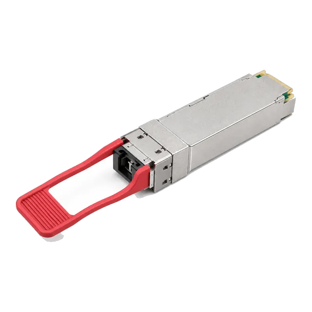
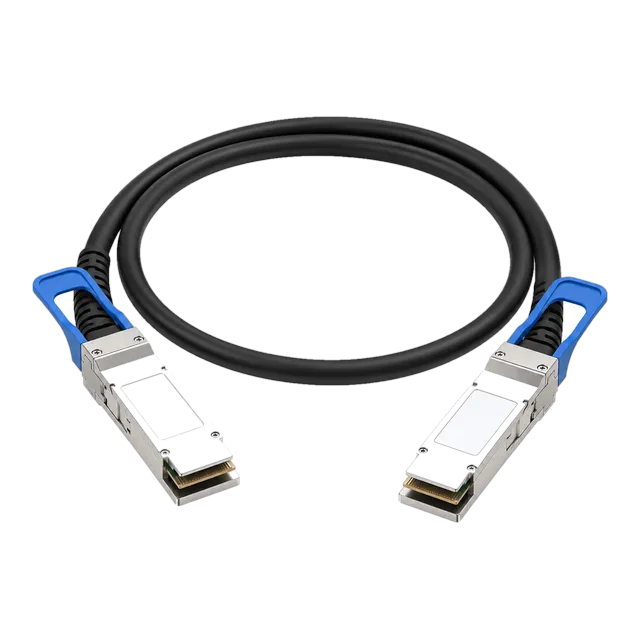
For in-row and in-hall distances the 100G QSFP28 SR4 listings, such as the 100G QSFP28 SR4 100m 850nm MPO/MTP Multimode DDM Optical module, address 850 nm parallel multimode over MPO-12. Where the route leaves the hall or runs on installed single-mode, the 100G QSFP28 CWDM4 2km 1310nm SMF Duplex LC DDM module and the 100G QSFP28 LR4 10km 1310nm Single-Mode Dual LC DDM module cover the two common duplex classes. For single-fiber single-mode routes, the 100GBASE-BX10 QSFP28 BiDi 1271/1331nm 10km Simplex LC SMF module is the relevant family. Very short in-rack connections between adjacent devices may instead use the 100G QSFP28 to QSFP28 Passive Direct Attach Copper Cable, which is a different physical connection and not a substitute for an installed fiber route.
05Link budget and reach considerations
Multimode parallel reach is governed by modal bandwidth rather than by attenuation, so the IEEE reach classes are used directly: 100GBASE-SR4 is specified to about 70 m on OM3 and 100 m on OM4. The check is then whether the total connector loss in the channel stays inside the channel insertion loss allowance printed in the module datasheet, counting roughly 0.3 to 0.75 dB per mated connector pair and about 0.1 dB per fusion splice.
Single-mode duplex links are budgeted arithmetically. Take fiber attenuation of roughly 0.35 dB/km at 1310 nm, add the connector and splice losses, and compare the total against the difference between minimum launch power and receiver sensitivity from the datasheet. Keep about 3 dB of unallocated margin for ageing, repair splices and future re-patching.
06Environment and power
QSFP28 optics in this class are normally commercial grade, rated 0 to 70 degrees Celsius at the case, so the question is whether the switch provides that case temperature under worst-case airflow rather than whether the room is cool. Check the airflow direction of the chassis, the density of populated cages, and any blanking panel policy, because a fully populated line card in a hot aisle is the realistic thermal case.
Power matters at scale. Optical modules draw more than a passive copper cable, and a row of parallel optics adds a measurable load to the switch power budget. Where two devices sit in the same rack, a passive DAC removes both the optical power draw and the thermal contribution, which is often the simplest optimisation available.
07Validation and acceptance
Acceptance should be written before the first module is fitted. A reasonable sequence is: verify each fiber strand or MPO position with a light source and power meter, confirm polarity end to end, fit the modules, then read digital diagnostics on both sides and compare transmit and receive power against the datasheet window.
After the link comes up, look at the interface counters rather than at the link LED. Record the pre-FEC error count if the platform exposes it, run traffic at line rate for a defined soak period, and confirm that no errored seconds accumulate. Capture the DDM values and the counter state as the as-built record, so that a future fault can be compared against a known good baseline instead of against memory.
08Procurement and BOM
A planning BOM for this concept is written per link, not as an order. Each link needs two matched transceivers, the jumpers at each end, and the trunk or patch cords in between. Where a link is asymmetric, for example a BiDi pair, the two ends are different part numbers and must be ordered as a matched set.
Spares are a policy decision rather than a fixed number. A common approach is to hold a defined percentage of each optic type used in production, sized against how quickly a replacement can be brought to site. Coding requirements are listed per host platform in the same document, so that an identical optical specification ordered for two different switch vendors is not accidentally treated as one line item.
09Common mistakes
The most frequent planning errors are mundane. Measuring rack-to-rack distance instead of installed cable length understates the route, sometimes by a large factor once risers and slack loops are included. Assuming OM4 where OM3 is installed pushes a parallel link past its reach class. Mixing MPO polarity methods between trunks and jumpers produces a link that appears dead although every component is healthy.
On the electrical side, treating a direct attach cable as a drop-in replacement for a fiber link fails, because the two are physically different connections. Finally, ordering a single part number for two different host platforms without confirming coding per platform creates modules that are correct optically but will not be accepted by one of the switches.
10Next step
Turn the survey into a document before asking for parts. Send the network diagram, the port inventory with host models and software releases, the fiber records including grade, length and connector type, and the quantity of links in scope.
Add the candidate modules from the 100G QSFP28 and DAC and AOC cable listings to an inquiry list so that the discussion starts from a concrete shortlist. The project worksheet on this site provides blank fields for the same inputs if no survey document exists yet. Because this is a planning concept rather than a delivered design, final part selection stays subject to engineering confirmation against the actual host platforms and the actual fiber plant.
11Design inputs to document
| Design input | What to record |
|---|---|
| Host platform and release | Exact switch model and software version at both ends, for coding confirmation. |
| Port and cage type | QSFP28 cage count, free ports and any breakout requirement. |
| Fiber grade | OM3, OM4 or single-mode, stated per route segment. |
| Installed length | Actual cable length including slack, risers and patch tails. |
| Connector arrangement | MPO-12 or duplex LC, plus the declared polarity method. |
| Mated pairs and splices | Count of panel adapters and fusion splices in the channel. |
| Thermal and power headroom | Chassis airflow direction and available port power budget. |
| Acceptance criteria | Target DDM window, soak duration and allowed error counters. |
12Planning bill of materials
| Item | Configuration | Quantity |
|---|---|---|
| 100G QSFP28 SR4 transceiver | 850 nm, MPO-12, OM3 or OM4 multimode, DDM | 2 per link |
| 100G QSFP28 CWDM4 or LR4 transceiver | 1310 nm region, duplex LC, single-mode, DDM | 2 per link, single-mode routes only |
| MPO-12 jumper | Polarity method to match the installed trunk | 2 per link |
| Duplex LC jumper | Single-mode or multimode to match the route | 2 per link, duplex routes only |
| 100G QSFP28 passive DAC | QSFP28 to QSFP28, AWG and length to specify | 1 per in-rack connection |
| Spare optics | Same coding and optical class as production | Percentage to specify |
Planning quantities only. The final bill of materials is confirmed with your quotation.
13Frequently asked questions
Can a DAC replace an installed fiber link?
No. A direct attach copper cable is a fixed-length copper assembly between two ports and cannot be patched through a fiber panel. It is useful for connections inside one rack, where it removes optical power draw and heat. If a structured fiber route already exists between the two devices, the correct choice is a transceiver pair matched to that fiber grade and length.
How much margin should a 100G single-mode budget keep?
Around 3 dB of unallocated margin is a reasonable planning figure once fiber attenuation, connector pairs and splices have been counted. That margin absorbs component ageing, later repair splices and re-patching. If the calculated margin is below that, either shorten the path, reduce mated pairs, or move up to a higher-power optical class rather than accepting a link that only just closes.
Does the same module work on any 100G switch?
Optically yes, administratively not always. Host platforms read the module EEPROM and may expect specific coding before they accept and fully report a transceiver. Coding is therefore confirmed per platform, and the same optical specification ordered for two different switch families is treated as two separate line items in the planning BOM.
What is the practical reach of 100GBASE-SR4?
About 70 m on OM3 and 100 m on OM4 under the IEEE reach classes. Those numbers assume a channel whose total connector loss stays inside the allowance in the module datasheet, so a route with several patch panels may fall short of the nominal figure. Count mated pairs at roughly 0.3 to 0.75 dB each before committing to a length.
Technical review note: confirm model-specific specifications with the product datasheet and the intended host documentation. Product images and application photographs are illustrative.
Discuss this with our team