Plan outdoor edge locations around worst-case PoE, enclosure temperature and a short copper tail, with fiber carrying the long path and its isolation benefits.
01The connection brief
Outdoor edge connectivity covers devices that need both data and power at a location with neither: cameras on poles, access control at gates, wireless access points on facades, sensors along a perimeter. This page is a planning concept explaining how such a location is specified, not a record of any delivered installation, and it names no site, customer or result.
The brief is a list of locations rather than a list of links. Each location has a device or group of devices, a distance from the nearest powered and connected point, an enclosure, and an exposure to weather and to electrical transients. The design problem is to deliver a reliable data path and an adequate power budget to each location, and then to make both survivable.
02The design inputs
Record, per location, the device count and the worst-case power draw of each device including heaters, motors and radios operating together, not the idle figure. Record the copper run length from the powering device to each endpoint, because the 100 m limit applies to power as well as to data.
Record the enclosure type and its expected internal temperature range, the available supply at the location, whether it is backed up, and how the location is reached for maintenance. Record the uplink: distance to the aggregation point, whether fiber exists, strand count and connector style. Finally record the exposure: whether the location is on an exposed pole, whether cables run between structures, and whether surge protection is already fitted.
03The topology and optical path
Two shapes recur. In the first, a single device sits at the location and a media converter with a PoE output port handles both conversion and powering, fed from a local supply. In the second, several devices are grouped at a gate, mast or building entry, and a compact switch with PoE ports serves them with a single fiber uplink back to the aggregation point.
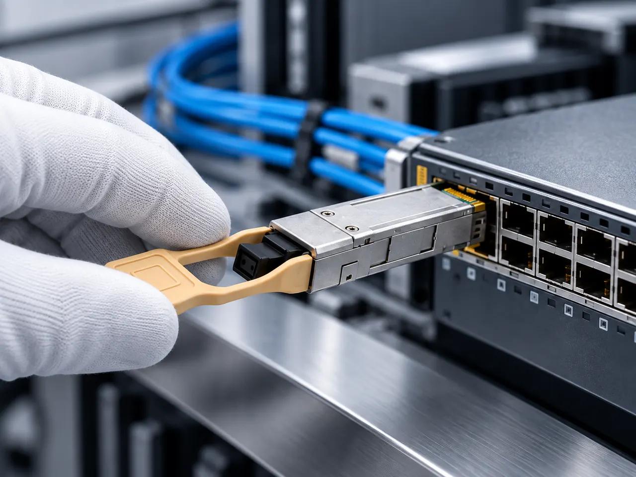
In both cases the fiber boundary should sit as close to the edge as practical, so that copper runs stay short and the long path between structures is optical and therefore galvanically isolated. Write the optical path as a chain including any bulkhead adapter on the enclosure, counting mated pairs at 0.3 to 0.75 dB and splices at about 0.1 dB.
04Product families to evaluate
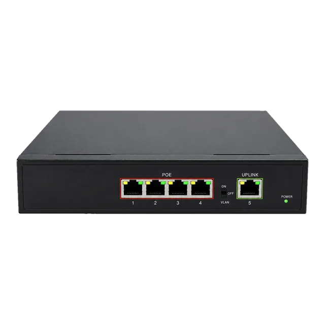
For grouped devices in a harsh location, the Outdoor Industrial Gigabit Ethernet Switch with five 10/100/1000Base-T ports, a 10 to 47 volt DC input, an aluminium alloy housing and a minus 40 to 85 degrees Celsius rating is the relevant family, with DIN rail or wall mounting. For a small powered group in a sheltered position, the Gigabit PoE IP Ethernet Switch with four 802.3af and 802.3at ports rated to 30 W per port plus a gigabit uplink applies.
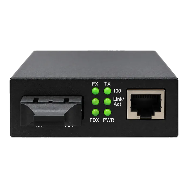
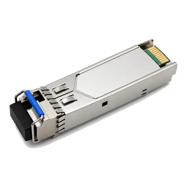
For single devices, the 1.25G SFP UTP PoE Media Converter provides an SFP fiber port, an RJ45 port with PoE output and a DC or mains supply option. Uplink optics come from the 1.25G SFP BiDi families for gigabit and the 10G SFP+ BiDi families where aggregate rate requires it.
05Link budget and reach considerations
Three budgets apply at an edge location. The power budget is the sum of worst-case device draw against what the source can supply on all ports simultaneously. The copper budget is the 100 m structured cabling limit, which also bounds how far power can travel. The optical budget is the usual calculation: roughly 0.35 dB/km at 1310 nm and roughly 0.22 dB/km at 1550 nm, plus mated pairs at 0.3 to 0.75 dB and splices at about 0.1 dB, with about 3 dB kept as unallocated margin.
Edge uplinks are usually short, so also check the maximum receiver input power and plan a fixed attenuator where a long-reach module would otherwise overload the far receiver.
06Environment and power
Temperature grade is the first decision. A sealed enclosure in direct sun runs well above ambient, so the industrial grade of minus 40 to 85 degrees Celsius should be the default for outdoor switches, converters and the transceivers fitted into them, rather than the commercial 0 to 70 degrees Celsius grade.
Power classes are the second. IEEE 802.3af provides 15.4 W at the source, 802.3at provides 30 W at the source, and 802.3bt extends this up to 90 W at the source for the highest classes. The device determines the class needed; the source must cover the total across all ports at once, plus its own consumption, plus cable losses. Where the location runs on DC, check the voltage at the terminals under full load rather than at the supply output.
07Validation and acceptance
Acceptance at an edge location should be performed at the location and under load. Verify the negotiated PoE class at each port and the actual power drawn with heaters, motors and radios active together, since that is the condition that exposes an undersized supply.
On the optical side, measure the uplink with a light source and power meter before mounting, then read digital diagnostics once the equipment is in place. Mechanically, check strain relief, gland sealing and fiber bend radius inside the enclosure. Finally test failure behaviour: remove the supply and confirm the expected alarm and the expected recovery, because an edge device that fails silently is worse than one that fails loudly.
08Procurement and BOM
The BOM is written per location and then summed. A location needs its switch or converter, a power arrangement sized for the worst case, mounting hardware, a bulkhead adapter, patch cords, and the uplink transceiver, with the far end of that uplink counted at the aggregation site.
Write the temperature grade against every outdoor line, transceivers included, and write the PoE class needed against every powered port. Where the uplink is single-fiber BiDi, list the two ends as separate matched items. Surge protection, where the risk assessment calls for it, belongs in the BOM from the start. Spares are best held as complete location kits, because attending a pole or mast is a scheduled task rather than a quick visit.
09Common mistakes
Budgeting PoE from idle draw is the most common and the most seasonal error, since heaters engage on the first cold night and the supply fails when it is least convenient. Specifying commercial temperature equipment for a sealed outdoor enclosure fails in the opposite season.
Other recurring mistakes are exceeding the 100 m copper limit and losing power before data, sizing the DC supply without including the switch's own consumption, omitting surge protection on cables that run between structures, ignoring bend radius inside a crowded enclosure, and fitting a long-reach optic on a short uplink so the receiver overloads. All are cheap to prevent in planning and expensive to fix at height.
10Next step
Prepare a location schedule listing devices, worst-case power draw and PoE class, copper run lengths, enclosure type and expected internal temperature, available supply and backup status, uplink distance and fiber availability.
Then add candidate ethernet switch, media converter and 1.25G SFP items to an inquiry list, with the temperature grade and the required PoE class written against each line rather than assumed from the product family. The project worksheet provides the same fields. As this page is a planning concept rather than a delivered installation, the power sums, the temperature grade, the surge assessment and the final part selection all remain subject to engineering confirmation against the actual devices, enclosures and site conditions.
11Design inputs to document
| Design input | What to record |
|---|---|
| Location schedule | Every outdoor point with the devices it must serve. |
| Worst-case power draw | Per device with heaters, motors and radios active together. |
| PoE class required | 802.3af, at or bt, stated per powered port. |
| Copper run length | Distance from the powering port to each endpoint, under 100 m. |
| Enclosure and temperature | Type, sun exposure and expected internal range. |
| Local supply | Voltage, available current and backup duration. |
| Uplink path | Fiber availability, measured length and connector style. |
| Surge exposure | Whether cables run between structures or up exposed masts. |
12Planning bill of materials
| Item | Configuration | Quantity |
|---|---|---|
| Outdoor industrial ethernet switch | 5 x gigabit RJ45, 10 to 47 V DC, minus 40 to 85 degrees C, DIN rail or wall | 1 per grouped location |
| PoE ethernet switch | 4 x 802.3af/at ports up to 30 W each plus gigabit uplink | 1 per sheltered powered group |
| PoE fiber media converter | SFP fiber port, RJ45 with PoE output, DC or mains supply | 1 per single-device location |
| 1.25G BiDi SFP uplink transceiver | 1310/1550 nm simplex LC, temperature grade per location | 2 per uplink, matched pair |
| Local DC supply | Voltage and current covering worst-case PoE plus switch draw | 1 per location |
| Surge protection unit | Type per risk assessment, on copper runs between structures | To specify per exposed run |
Planning quantities only. The final bill of materials is confirmed with your quotation.
13Frequently asked questions
How much power does each PoE standard deliver?
IEEE 802.3af provides 15.4 W at the source, 802.3at provides 30 W at the source, and 802.3bt extends the range up to 90 W at the source for its highest classes. The device at the far end always receives less than the source figure because of cable loss. Size the source for the worst case on every port at once, not for the average.
Can PoE travel further than 100 m?
Not within the standard. The 100 m structured cabling limit bounds power as well as data, and voltage drop over a long run also reduces what reaches the device. The correct arrangement is to move the powering point closer using a fiber uplink to a local switch or converter, which keeps the copper short and isolates the long path optically.
Which temperature grade suits an outdoor enclosure?
The industrial grade of minus 40 to 85 degrees Celsius should be the default assumption for outdoor equipment and for the transceivers fitted into it. A sealed box in direct sun runs well above the surrounding air, so the commercial 0 to 70 degrees Celsius grade is frequently exceeded. A commercial transceiver inside an industrial switch limits the whole assembly.
Why is surge protection part of the network plan?
Because copper that runs between structures or up an exposed mast can carry induced transients into equipment at both ends. Moving the long path to fiber removes that coupling entirely, which is the strongest reason to place the fiber boundary close to the edge. Where copper between structures is unavoidable, surge protection belongs in the BOM from the outset.
Technical review note: confirm model-specific specifications with the product datasheet and the intended host documentation. Product images and application photographs are illustrative.
Discuss this with our team