In a plant cabinet the temperature grade, DC supply and mounting decide the design before data rate does, and the transceiver grade must match the switch grade.
01The connection brief
Industrial cabinet connectivity covers the network equipment that lives inside a plant, trackside or utility enclosure rather than in a communications room. This page is a planning concept explaining how such a cabinet is specified. It does not describe a completed installation and contains no site, customer or measured outcome.
The brief usually starts from a cabinet that already exists and already contains control equipment. The network has to fit into the space, the DC supply and the thermal envelope that the cabinet provides, and it has to survive whatever the surroundings do. That means the design inputs are as much mechanical and electrical as they are about data rates, and skipping them is the main reason industrial network equipment fails early.
02The design inputs
Record the internal temperature range the cabinet actually reaches, not the ambient outside it, since a sealed enclosure in sunlight runs well above the air temperature. Record the available DC supply voltage and its tolerance, whether it is backed up, and how much current is free.
Record the mounting method available, typically DIN rail or a wall plate, and the free rail length in millimetres. Record the port requirement: how many copper ports for local devices, what speed each needs, and whether any device requires PoE. Record the uplink requirement, its distance, and whether fiber is available. Finally, record the mechanical environment: vibration, dust, corrosive atmosphere and any washdown, since these decide housing and connector choices.
03The topology and optical path
A typical cabinet holds one compact switch serving local devices over short copper runs, with a single uplink leaving the cabinet toward an aggregation point. The copper runs inside the plant are kept short and routed away from drives and motors, because variable frequency drives are the dominant noise source on a factory floor.
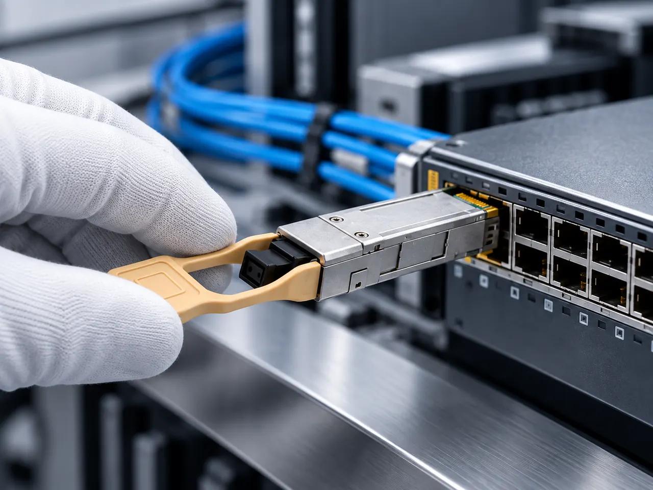
The uplink is normally fiber, and not only for distance. Fiber provides galvanic isolation between the cabinet and the aggregation point, which removes earth potential differences between buildings or between machine sections as a fault source. Write the optical path out as a chain including any bulkhead adapters on the cabinet gland plate, counting each mated pair at 0.3 to 0.75 dB.
04Product families to evaluate
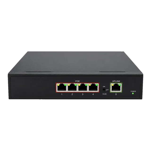
For the cabinet switch itself, the Outdoor Industrial Gigabit Ethernet Switch with five 10/100/1000Base-T RJ45 ports is the relevant family: an aluminium alloy housing, DIN rail or wall mounting, a wide 10 to 47 volt DC input and a minus 40 to 85 degrees Celsius rating. Where powered devices sit in or near the cabinet, the Gigabit PoE IP Ethernet Switch with four 802.3af and 802.3at ports and one uplink covers a small powered group in a conditioned location.
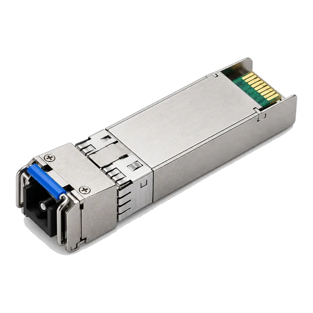
For the uplink optics, the 10G SFP+ BiDi BX20 20km 1270/1330nm Industrial-Grade Transceiver and the 10G SFP+ BiDi BX60 60km families address single-fiber uplinks, and the 1.25G SFP families cover gigabit uplinks where 10 gigabit is not required.
05Link budget and reach considerations
Industrial uplinks are usually short by optical standards, so the budget rarely fails on attenuation. Calculate it anyway using roughly 0.35 dB/km at 1310 nm and roughly 0.22 dB/km at 1550 nm, adding mated pairs at 0.3 to 0.75 dB and splices at about 0.1 dB, and keep about 3 dB unallocated.
The more likely problem is the opposite. A 60 km or 80 km module across a 300 m plant link can deliver more power than the far receiver tolerates, causing errors that look like interference. Check the maximum receiver input power in the datasheet and plan a fixed attenuator where the calculation predicts overload. On the copper side, the 100 m structured cabling limit still applies to every run inside the plant.
06Environment and power
Temperature grade is the first specification, not an afterthought. Commercial equipment rated 0 to 70 degrees Celsius is unsuitable for most sealed cabinets, and the industrial grade of minus 40 to 85 degrees Celsius should be the default assumption for both the switch and any transceiver fitted into it. A transceiver rated only to 70 degrees Celsius inside an 85 degree switch is a latent fault.
Power must be planned as a load, not as a plug. Record the DC voltage, the switch consumption, any PoE load it must source, and the headroom left in the cabinet supply. Include the heat the equipment adds to the enclosure, since that heat raises the internal temperature that the temperature grade then has to cover.
07Validation and acceptance
Acceptance for an industrial cabinet has a mechanical component. Confirm that the DIN rail mounting is secure and that cables are strain relieved, because vibration works connectors loose over months rather than minutes. Confirm that the fiber bend radius is respected inside the enclosure, which is where it is most often violated.
Electrically, measure the supply voltage at the switch terminals under load rather than at the power supply output. Read transceiver digital diagnostics and compare received power against the calculation. Then run the plant, not just the network: a link that is clean with machinery stopped and errored with drives running points at a routing or bonding problem that should be fixed before handover, not after.
08Procurement and BOM
The cabinet BOM is per cabinet rather than per link. It contains the switch, its DC supply arrangement, the mounting hardware, the uplink transceiver pair, the patch cords and any bulkhead adapters on the gland plate.
State the temperature grade explicitly on every line, including the transceivers, because the same optical specification is commonly available in both commercial and industrial grades and the grade is easy to lose in an order. Where the uplink is single-fiber BiDi, list the two ends as separate matched items. Record the coding for the aggregation switch, confirmed per platform, and hold spares for the cabinet switch as a unit rather than by component, since plant downtime is the expensive part.
09Common mistakes
Specifying an industrial switch and then fitting a commercial temperature transceiver into it is the most frequent error, and it produces failures that appear only in summer. Measuring ambient air temperature instead of internal cabinet temperature produces the same result by a different route.
Other recurring mistakes are sizing the DC supply without including the PoE load, routing copper alongside drive cables, ignoring bend radius inside a crowded enclosure, and fitting a long-reach optic on a short plant link so the receiver overloads. Finally, testing the network with the plant idle hides exactly the interference problems that industrial installations exist to withstand, and those problems then appear during production rather than during commissioning.
10Next step
Produce a cabinet schedule: internal temperature range, available DC supply and free current, mounting space in millimetres, port count and speed per device, PoE requirement, and uplink distance and fiber availability.
Then add candidate ethernet switch and 10G SFP+ items to an inquiry list, with the temperature grade written against every line, including the transceivers as well as the switch itself. The project worksheet provides blank fields for the same inputs. This page is a planning reference rather than a delivered cabinet design, so the mechanical fit, the supply sizing, the temperature grade and the final part selection all remain subject to engineering confirmation against the actual enclosure and the equipment already inside it.
11Design inputs to document
| Design input | What to record |
|---|---|
| Internal cabinet temperature | Measured or estimated range inside the enclosure, not ambient air. |
| DC supply | Voltage, tolerance, free current and backup status. |
| Mounting space | DIN rail length or wall plate area available, in millimetres. |
| Port schedule | Local device count, speed per port and any PoE requirement. |
| Uplink path | Distance, fiber availability, strand count and connector style. |
| Mechanical environment | Vibration, dust, corrosive atmosphere or washdown exposure. |
| Isolation requirement | Whether fiber is needed to break an earth potential difference. |
12Planning bill of materials
| Item | Configuration | Quantity |
|---|---|---|
| Industrial gigabit ethernet switch | 5 x 10/100/1000Base-T, 10 to 47 V DC, minus 40 to 85 degrees C, DIN rail | 1 per cabinet |
| PoE ethernet switch | 4 x 802.3af/at ports up to 30 W per port plus 1 uplink | 1 per powered device group, conditioned locations |
| 10G SFP+ BiDi uplink transceiver | 1270/1330 nm simplex LC, industrial temperature grade | 2 per uplink, matched pair |
| Bulkhead fiber adapter | Connector style to match the patch cords, gland plate mount | 1 per cabinet entry |
| DC power arrangement | Voltage and current sized to include the PoE load | 1 per cabinet |
Planning quantities only. The final bill of materials is confirmed with your quotation.
13Frequently asked questions
Does an industrial switch require industrial transceivers?
If the cabinet reaches temperatures above the commercial ceiling, yes. A switch rated to 85 degrees Celsius fitted with a transceiver rated only to 70 degrees Celsius is limited by the transceiver, and the resulting faults tend to appear seasonally and intermittently. Write the temperature grade on every BOM line, transceivers included, so it survives the ordering process.
Why use fiber for a short uplink inside a plant?
For isolation as much as for distance. A fiber uplink removes any galvanic path between the cabinet and the aggregation point, so earth potential differences between machine sections or buildings cannot drive current through the network equipment. It is also immune to the electromagnetic noise produced by variable frequency drives, which is the dominant interference source on a plant floor.
How should the cabinet DC supply be sized?
Add the switch consumption, the total PoE load it must source, and any other equipment on the same rail, then leave headroom for the worst case rather than the typical case. Measure the voltage at the switch terminals under load, because voltage drop across long DC runs inside a machine is real and a wide input range exists partly to absorb it.
What should acceptance testing include beyond the link?
Run the test with the plant running. Interference from drives and contactors appears only under load, so a link verified with machinery idle proves very little. Combine that with a mechanical check of strain relief, DIN rail seating and fiber bend radius inside the enclosure, since vibration-driven failures develop over months and are cheapest to prevent at handover.
Technical review note: confirm model-specific specifications with the product datasheet and the intended host documentation. Product images and application photographs are illustrative.
Discuss this with our team