Active point-to-point BiDi access trades port count for dedicated capacity: plan matched wavelength pairs, budget both directions and size the node by cages, not by fiber.
01The connection brief
This concept covers active point-to-point gigabit access built from BiDi SFP optics, the arrangement that sits alongside passive optical networks rather than inside them. It is a planning reference describing how such an access layer is specified, not a record of any delivered network, and it names no operator, area or subscriber count.
The brief is a set of subscriber or building terminations served from one aggregation node over dedicated strands. Unlike a passive splitter tree, each termination has its own optical path and its own dedicated bandwidth, which simplifies fault isolation and capacity planning at the cost of one aggregation port per subscriber. The planning question is how many ports, over what distances, at what rate, and with what termination at the customer end.
02The design inputs
Record the termination count and the measured route length to each one, distinguishing the longest route because it sets the optical class for the whole batch if a single part number is preferred. Record the strand assignment per termination and the position of every splice and street panel.
Record the aggregation platform: model, software release, SFP cage count, uplink capacity and the oversubscription ratio the design accepts. Record the service rate per termination now and at the next tier, since a 1 gigabit service and a 2.5 gigabit service use different module families. Record what terminates the customer end, a small switch, a router with an SFP cage, or a media converter feeding an RJ45 device, and record the environment that equipment sits in.

03The topology and optical path
The topology is a star. One aggregation switch, one strand per termination, one customer unit per strand. Each strand carries the downstream wavelength in one direction and the upstream wavelength in the other, so the two ends are complementary module types.
The wavelength plan should be written down explicitly: which wavelength faces the network and which faces the subscriber, applied consistently across the whole deployment. Consistency matters at scale because a field engineer replacing a unit needs to know which type to carry without opening a design document. Write the optical path per termination as a chain from aggregation module through jumper, panel, outside plant strand, splices, street panel, drop and customer module, counting mated pairs at 0.3 to 0.75 dB.
04Product families to evaluate
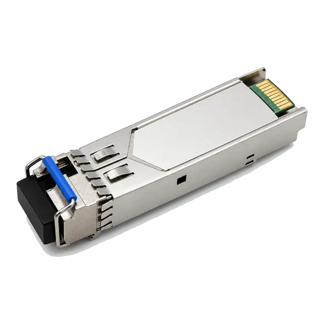
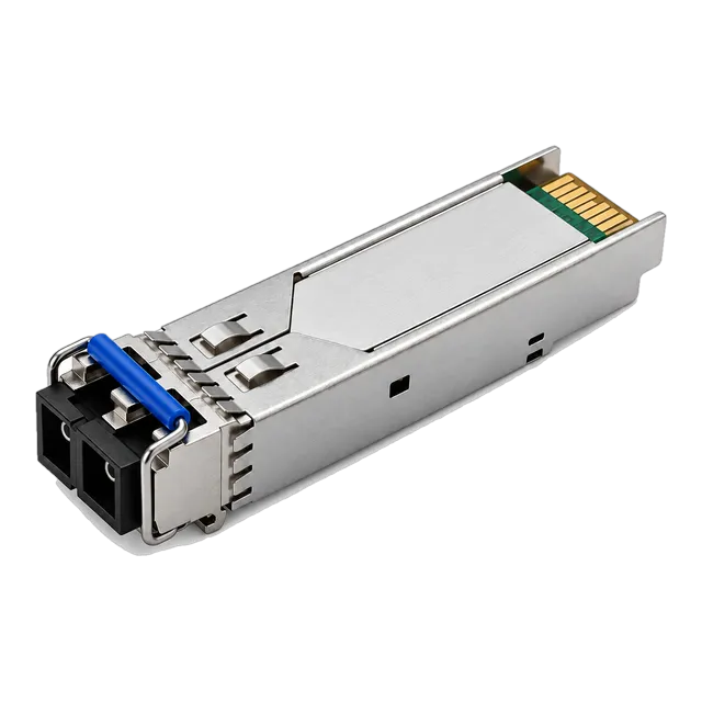
The 1.25G SFP BiDi families are the core of a gigabit build. The 1.25G BiDi Single-Fiber SFP Transceiver 1310nm/1550nm 20km covers typical access reach, the 1.25G BiDi SFP 3km Tx1310nm/Rx1490nm Simplex LC SMF module suits dense short drops, and the 1.25G BiDi SFP 1310nm/1490nm 60km LC DDM Single-Fiber module addresses outlying terminations. Where the installed panels use SC, the 1.25G SFP BiDi Optical Module 20km 1310nm/1550nm SC variant applies.
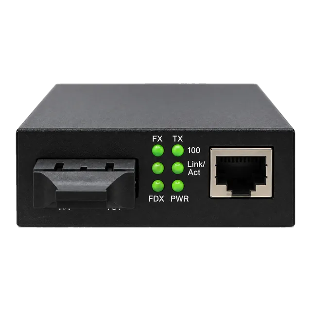
For 2.5 gigabit services the 2.5G BiDi SFP-2.5G-BX120 Single-Fiber 1490/1550nm 120km module is the long-reach option, with the SFP-2.5G-LX20-SM1310 2.5G Single-Mode 1310nm 20km Duplex module where two strands exist. Customer-side conversion uses the 2.5G Fiber to Ethernet Media Converter or the gigabit converter families.
05Link budget and reach considerations
Budget each direction separately because the wavelengths differ. Use roughly 0.35 dB/km at 1310 nm and roughly 0.22 dB/km at 1550 nm, add mated connector pairs at 0.3 to 0.75 dB and fusion splices at about 0.1 dB, and compare each direction against the launch power and sensitivity figures for the module at that end. Keep about 3 dB of unallocated margin for ageing and future repair splices.
Access routes accumulate connections: an aggregation panel, a street cabinet, a building entry and a customer socket can easily place four or more mated pairs in a path. On a 15 km route those connections can contribute as much loss as several kilometres of fiber, so count them rather than rounding them away.
06Environment and power
The aggregation node is usually a conditioned room where commercial grade optics rated 0 to 70 degrees Celsius are appropriate. The customer end is not. A wall-mounted unit in an unheated meter cupboard, a street cabinet or a rooftop box sees a much wider range, and the industrial grade of minus 40 to 85 degrees Celsius is the safer specification there.
Power at the customer end is often the least controlled part of the design. Record the supply, whether it is on the customer side of any protection, and whether a converter needs a local adapter. Where the same enclosure feeds a device that also needs power, a converter with PoE output can remove one supply and one point of failure from a location that is difficult to attend.
07Validation and acceptance
Test each strand end to end at both working wavelengths with a light source and power meter before the customer unit is installed, and take an OTDR trace where splices exist so that their positions are on record.
With both modules fitted, read digital diagnostics at each end, confirm the received power sits inside the datasheet window rather than merely above sensitivity, and verify from the reported wavelengths that the correct complementary pair is installed. Run a throughput test at the contracted service rate for a defined period and confirm that no errors accumulate. Record the strand assignment, the loss per direction and the DDM values as the baseline for that termination, since access faults are diagnosed by comparison.
08Procurement and BOM
Plan the BOM as matched pairs throughout. Each termination consumes one network-side module and one subscriber-side module, and these are different part numbers with the same quantity. Ordering a single part number produces modules that cannot link to each other.
List jumpers in the connector style that matches the installed panels, customer premises converters where the termination is copper, and the temperature grade required per location class. Include the aggregation switch port count as a separate check, since an active point-to-point design consumes one port per subscriber and that is the constraint that usually governs how far a node can grow. Coding for the aggregation platform is confirmed per platform and recorded with the BOM.
09Common mistakes
Ordering one BiDi part number for both ends is the classic error. Second is applying the wavelength plan inconsistently across an area, so that field replacement becomes guesswork. Third is budgeting only the 1550 nm direction and being caught by the higher attenuation of the 1310 nm path on the longest routes.
Fourth is specifying commercial grade optics for customer locations that are effectively outdoors. Fifth is planning aggregation capacity from subscriber count alone without checking the uplink and the acceptable oversubscription. Sixth is treating a point-to-point BiDi design as if it were a splitter tree, which leads to misplaced expectations about how many terminations a single aggregation port can serve and how the optical budget is shared.
10Next step
Prepare a termination schedule with route lengths, strand assignments, service rates, customer-end equipment and location class. Add the aggregation platform details and the intended wavelength plan.
Then add candidate 1.25G SFP, 2.5G SFP and media converter items to an inquiry list, clearly separating the network-side quantity from the subscriber-side quantity so that the matched pairs cannot be collapsed into one line. The project worksheet provides blank fields for the same inputs. Because this page is a planning concept rather than a built access network, the reach classes, the per-direction budgets and the aggregation sizing should all be recalculated against real strand measurements and the real platform port count before any procurement decision is made.
11Design inputs to document
| Design input | What to record |
|---|---|
| Termination schedule | Count of terminations with measured route length to each. |
| Strand assignment | Which strand serves which termination, with splice positions. |
| Service rate | Contracted rate per termination now and at the next tier. |
| Wavelength plan | Which wavelength faces the network, applied consistently. |
| Aggregation platform | Model, software release, free cages and uplink capacity. |
| Customer equipment | Switch, router with SFP cage, or converter to RJ45. |
| Location class | Indoor, cupboard or outdoor, setting the temperature grade. |
| Oversubscription target | Accepted ratio of subscriber capacity to node uplink. |
12Planning bill of materials
| Item | Configuration | Quantity |
|---|---|---|
| 1.25G BiDi SFP, network side | 1310/1550 nm, simplex LC, single-mode, reach class per route | 1 per termination |
| 1.25G BiDi SFP, subscriber side | Complementary wavelength assignment, matching reach class | 1 per termination |
| 2.5G BiDi SFP | 1490/1550 nm, simplex LC, single-mode, long-reach class | 2 per upgraded termination, matched pair |
| Customer fiber media converter | SFP or fixed fiber port to RJ45, rate per service tier | 1 per copper-terminated subscriber |
| Simplex patch cords | LC or SC to match installed panels, single-mode | 2 per termination |
Planning quantities only. The final bill of materials is confirmed with your quotation.
13Frequently asked questions
How does this differ from a passive optical network?
A passive optical network shares one feeder fiber across many subscribers through an optical splitter, so bandwidth and optical budget are shared. This concept keeps one dedicated strand and one aggregation port per termination, giving dedicated capacity and simpler fault isolation at the cost of port count and fiber count. The two are planned differently and their budgets are not interchangeable.
Which direction limits reach on a BiDi access link?
Usually the 1310 nm direction, because attenuation at 1310 nm is roughly 0.35 dB/km against roughly 0.22 dB/km at 1550 nm. On a long route that difference is several decibels. Budget both directions separately against the launch power and sensitivity of the module at each end rather than assuming the shorter wavelength has the same headroom.
Why write down a wavelength plan?
So that field replacement is deterministic. In a deployment of many terminations, an engineer needs to know from the location alone which of the two complementary module types to carry. A plan applied consistently across an area turns that into a rule; an inconsistent plan turns every replacement into a site investigation and invites the wrong module to be fitted.
What limits the size of an aggregation node?
Port count first, then uplink capacity. Every termination consumes one SFP cage, so a node's growth stops at its available cages regardless of how much fiber is spare. The second limit is the node uplink against the accepted oversubscription ratio. Record both constraints before planning an expansion, because they are reached at different points.
Technical review note: confirm model-specific specifications with the product datasheet and the intended host documentation. Product images and application photographs are illustrative.
Discuss this with our team