Module selection is a calculation on documented facts about the cable plant, so measure the route, the fiber grade and the loss before choosing a reach class.
01Why documentation comes before selection
Choosing a transceiver is arithmetic performed on facts about the fiber. Reach class, wavelength plan and even form factor follow from route length, fiber grade and link loss, so a selection made before those facts are known is a guess with a purchase order attached. The cost of getting it wrong is asymmetric: a module bought one class too short produces a link that will not come up, and a module bought several classes too long can saturate the far receiver and needs attenuators. Documenting the path first also produces a record that keeps paying back, because every future change on that route, every fault, and every capacity upgrade starts from the same set of facts. Treat this as a short structured survey rather than as paperwork.
02Record the route the light takes
Length means the optical path, not the distance between buildings on a map. Fiber follows ducts, risers, tray routes and service loops, and the difference between the straight line and the installed length can be substantial on a campus. Use the cable sheath markings where the cable is accessible, the as-built cable schedule where one exists, or an optical time domain reflectometer measurement where neither is reliable. Record which method was used, because an estimate and a measurement deserve different levels of confidence in a loss budget. Note the full path including patch cords at each end and any slack coiled at joint boxes. Where the route is leased from a carrier, ask for the circuit length and treat the figure as an input to be confirmed rather than as a certainty.
03Establish the fiber type and grade
Record whether the route is single-mode or multimode and, for each, the grade. Single-mode is usually specified to ITU-T G.652.D on modern installations, but older plant may be G.652.B or an earlier variant with a water peak that affects certain wavelengths. Multimode is graded OM1 through OM5, and the distinction matters sharply at 10 Gb/s and above: legacy OM1 62.5 micron fiber will not support the same links as laser-optimised OM3 or OM4. Establish the grade from the cable jacket print, the original installation certificate or a test report, not from the jacket colour, since aqua and lime sheaths are widely reused and patch cords are frequently mismatched to the trunk. Where a path crosses several cable sections, record each section, as the link is limited by the weakest one.
04Strand count, allocation and spares
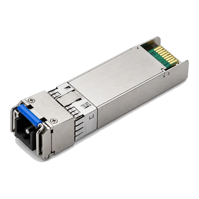
Document how many strands exist on the route, how many are already in use, what they carry, and how many are available. Then record which strands this link will occupy, by their numbering at each patch panel. This is the information that decides whether a two-fiber design is possible or whether a single-fiber BiDi approach is needed, and it is the information most often missing when a new service is requested on an existing route. Note any strands known to be broken or of poor quality from previous testing, so they are not allocated by accident. Where strands are leased by the pair, record the commercial arrangement too, since that frequently makes BiDi modules such as our 10G SFP+ BiDi BX20 and BX60 items the economical choice rather than merely a technical one.
05Terminations, panels and connector types
Count and describe every mated connection the light passes through, from the module at one end to the module at the other. For each, record the location, the connector type, whether it is a patch panel adapter, a cassette port or a direct connection, and whether it is physical contact, ultra physical contact or angled physical contact. Connector polish type matters because angled and non-angled connectors must not be mated, and mixing them damages end faces and produces high loss. Record the connector at the module end separately, since that determines the patch cord: duplex LC for most rates, simplex LC or SC for single-fiber BiDi, MPO-12 for parallel optics. The count of mated pairs is the single largest variable in most loss budgets.
06Splices and joint locations
Record the number and location of fusion splices along the route, including those in joint enclosures, at building entrances and at any repair point. A fusion splice contributes roughly 0.1 dB, which is small individually but significant on a route with many joints, and a poorly made or ageing splice can contribute far more. Knowing where the joints are also shortens fault finding, because an OTDR event can be matched to a physical location instead of being estimated from a distance figure. Note any repair splices added after the original installation, with their dates, since a route that has been cut and repaired several times will have drifted from its commissioning loss figure and is more likely to drift again.
07Measure insertion loss, do not assume it
The number that decides the module is the measured end-to-end insertion loss of the channel, taken with an optical loss test set at the wavelengths the link will use: 850 nm and 1300 nm for multimode, 1310 nm and 1550 nm for single-mode. Measure in both directions, since the two can differ, and use a reference method that matches the connector arrangement being tested. Compare the result with a calculation from first principles, adding fiber attenuation at roughly 0.35 dB per kilometre at 1310 nm and roughly 0.22 dB per kilometre at 1550 nm on single-mode, around 3 dB per kilometre at 850 nm on multimode, 0.3 to 0.75 dB per mated connector pair and about 0.1 dB per splice. A measurement far above the calculation indicates a problem to resolve before selecting a module.
08OTDR traces add location, not just loss
An optical loss test set gives one number for the whole channel; an optical time domain reflectometer shows where the loss occurs. A trace identifies individual connector and splice events with their loss and reflectance, shows macro-bends as loss without reflection, and reveals the true fiber length. Take a trace on each strand at commissioning and store it, because a later trace compared against the original makes a new event obvious in minutes. Note that an OTDR has a dead zone near the launch point and may miss events very close to the patch panel, which is why it complements rather than replaces the loss measurement. Record the launch conditions and settings used, otherwise a future comparison will be arguing about methodology instead of about the fiber.
09Inspect and record end faces
Contamination is the most common cause of optical link problems and the easiest to prevent. Inspect every connector end face with a fiber scope before mating, clean it if it fails inspection, and inspect again after cleaning. Record that this was done as part of the commissioning documentation, ideally with images for the connections at each end of a critical link. This matters for the documentation set because a link that degrades later can then be compared with a known clean starting point. Where MPO connectors are used for parallel optics, the requirement is stronger, since one ferrule carries twelve cores and a single particle can affect one lane of a four-lane link, producing errors that look like a module fault.
10Polarity and labelling scheme
For duplex links, record which strand carries which direction at each panel and confirm that the numbering convention is consistent along the route. For parallel links using MPO cabling, record the polarity method chosen for the site, A, B or C, and confirm that every trunk, cassette and patch cord in the channel conforms to it. Record the pinned or unpinned status of each MPO interface as well, since a mated pair requires exactly one of each. Then document the labelling scheme itself: what is written on the panel port, on the cable and on the module, and where the mapping between them is held. A route that is well tested but poorly labelled will still generate the same faults, because the next engineer will patch the wrong port.
11Environment and mechanical exposure
Record where the cable physically runs and what it is exposed to: internal containment, external duct, direct burial, aerial span, along a bridge or in an industrial area. Note temperature extremes at the equipment ends, since that decides the module temperature grade between the commercial 0 to 70 degrees Celsius and industrial minus 40 to 85 degrees Celsius options. Note any section subject to vibration, movement or third-party works, as those are the sections that will need repair splices later. Where equipment sits in a street cabinet or an unconditioned room, note it against the link, because that information will be needed again when a module is replaced and someone has to decide which grade to order.
12Keep it as-built and keep it accessible
Documentation that is created for a project and never updated becomes actively misleading. Make one person responsible for the record, define what triggers an update, and version the document with dates and a short change log. The events that must trigger an update are re-patching, repair splices, panel changes, module replacement, and any measurement taken during fault finding. Store the loss measurements, OTDR traces, end-face inspection records, polarity method, strand allocation and commissioning diagnostic baselines together rather than scattered across mailboxes. When the next link on that route is specified, or the next fault occurs, this file is what turns a multi-day investigation into a calculation, and it is what a supplier needs in order to quote a module without guessing.
13Frequently asked questions
What do I need to know about my fiber before choosing a transceiver?
Route length by the path the cable takes, fiber type and grade, the number of mated connections and splices, the measured end-to-end loss at the working wavelengths, the connector type at the module, strand availability, the polarity arrangement for parallel links, and the temperature at each equipment end. Those facts determine the reach class, wavelength plan and temperature grade you need.
How do I calculate fiber link loss?
Add fiber attenuation, roughly 0.35 dB per kilometre at 1310 nm and 0.22 dB per kilometre at 1550 nm on single-mode and around 3 dB per kilometre at 850 nm on multimode, plus 0.3 to 0.75 dB per mated connector pair and about 0.1 dB per fusion splice. Keep a design margin, commonly 3 dB, and compare the total with the module budget.
Is an OTDR test necessary before installing optics?
It is not always necessary, but it is valuable. An optical loss test set gives the total channel loss, which is what the module budget needs; an OTDR shows where that loss occurs and records the individual connector, splice and bend events. A commissioning trace stored for comparison makes later fault finding much faster, since a new event stands out immediately.
How can I tell whether my multimode fiber is OM3 or OM4?
Read the print on the cable jacket, or check the original installation certificate or test report. Do not rely on jacket colour, because aqua and lime sheaths are reused across grades and patch cords frequently do not match the trunk. Where a route crosses several cable sections, establish the grade for each one, since the link is limited by the weakest section.
Why does my link work but show errors after re-patching?
Most often contamination on a connector that was unmated and re-mated without inspection, or an extra mated pair added to a channel with little loss margin. Compare the receive power with the value recorded at commissioning, inspect and clean every connector disturbed during the change, and recount the mated pairs in the channel against the module's loss budget.
Technical review note: confirm model-specific specifications with the product datasheet and the intended host documentation. Product images and application photographs are illustrative.
Discuss this with our team